Page 1809 of 2453
GD(H6DO)-197
Diagnostic Trouble Code (DTC) Detecting Criteria
GENERAL DESCRIPTION
DY:DTC P2096 POST CATALYST FUEL TRIM SYSTEM TOO LEAN (BANK 1)
1. OUTLINE OF DIAGNOSIS
Detect the malfunction of fuel system from the size of the sub feedback learning value.
Control the sub feedback learning and judge as NG when the learning value is in the lean zone.
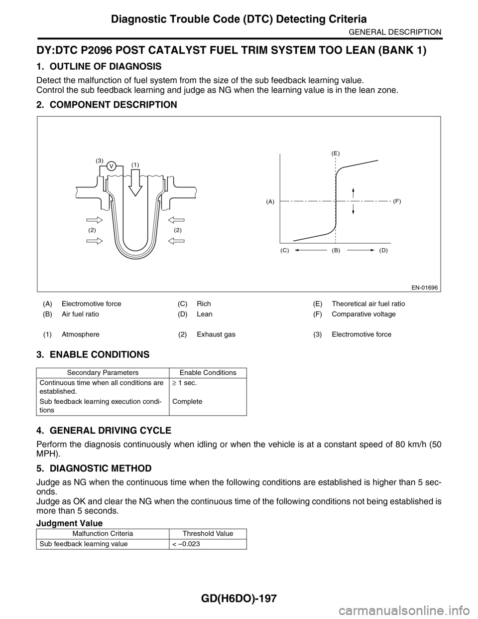
2. COMPONENT DESCRIPTION
3. ENABLE CONDITIONS
4. GENERAL DRIVING CYCLE
Perform the diagnosis continuously when idling or when the vehicle is at a constant speed of 80 km/h (50
MPH).
5. DIAGNOSTIC METHOD
Judge as NG when the continuous time when the following conditions are established is higher than 5 sec-
onds.
Judge as OK and clear the NG when the continuous time of the following conditions not being established is
more than 5 seconds.
(A) Electromotive force (C) Rich (E) Theoretical air fuel ratio
(B) Air fuel ratio (D) Lean (F) Comparative voltage
(1) Atmosphere (2) Exhaust gas (3) Electromotive force
Secondary Parameters Enable Conditions
Continuous time when all conditions are
established.
≥ 1 sec.
Sub feedback learning execution condi-
tions
Complete
Judgment Value
Malfunction Criteria Threshold Value
Sub feedback learning value < –0.023
EN-01696
(3)V(1)
(2) (2)
(E)
(F)
(C) (B) (D)
(A)
Page 1811 of 2453
GD(H6DO)-199
Diagnostic Trouble Code (DTC) Detecting Criteria
GENERAL DESCRIPTION
DZ:DTC P2097 POST CATALYST FUEL TRIM SYSTEM TOO RICH (BANK 1)
1. OUTLINE OF DIAGNOSIS
Detect the malfunction of fuel system from the size of the sub feedback learning value.
Sub feedback learning is being performed. When the learning value goes to the rich side, judge as NG.
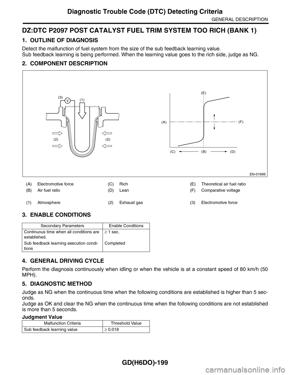
2. COMPONENT DESCRIPTION
3. ENABLE CONDITIONS
4. GENERAL DRIVING CYCLE
Perform the diagnosis continuously when idling or when the vehicle is at a constant speed of 80 km/h (50
MPH).
5. DIAGNOSTIC METHOD
Judge as NG when the continuous time when the following conditions are established is higher than 5 sec-
onds.
Judge as OK and clear the NG when the continuous time when the following conditions are not established
is more than 5 seconds.
(A) Electromotive force (C) Rich (E) Theoretical air fuel ratio
(B) Air fuel ratio (D) Lean (F) Comparative voltage
(1) Atmosphere (2) Exhaust gas (3) Electromotive force
Secondary Parameters Enable Conditions
Continuous time when all conditions are
established.
≥ 1 sec.
Sub feedback learning execution condi-
tions
Completed
Judgment Value
Malfunction Criteria Threshold Value
Sub feedback learning value≥ 0.018
EN-01696
(3)V(1)
(2) (2)
(E)
(F)
(C) (B) (D)
(A)
Page 1846 of 2453
IN(H6DO)-4
Air Cleaner Element
INTAKE (INDUCTION)
2. Air Cleaner Element
A: REMOVAL
1) Disconnect the ground cable from battery.
2) Disconnect the connector from mass air flow and
intake air temperature sensor.
3) Remove the clip (A) securing upper side of air
cleaner case.
4) Pull the air cleaner case (rear) backward of the
vehicle, and remove the air cleaner element.
B: INSTALLATION
Install in the reverse order of removal.
NOTE:
Fasten with a clip after inserting the lower tab of
case.
C: INSPECTION
Replace if excessively damaged or dirty.
IN-02143
IN-02144
(A)
IN-02145
Page 1847 of 2453
IN(H6DO)-5
Air Cleaner Case
INTAKE (INDUCTION)
3. Air Cleaner Case
A: REMOVAL
1) Disconnect the ground cable from battery.
2) Remove the air intake duct.
7, REMOVAL, Air Intake Duct.>
3) Disconnect the connector from mass air flow and
intake air temperature sensor.
4) Loosen the clamps (A) which connect the air
cleaner case to intake duct.
5) Remove the clip (B) securing the upper side of
air cleaner case.
6) Remove the air cleaner case (rear) and air
cleaner element.
7) Remove the bolts (A) and nut (B) which secure
the air cleaner case to body.
8) Remove the air cleaner case (front).
B: INSTALLATION
Install in the reverse order of removal.
Tightening torque:
Bolt (A): 6.0 N·m (0.6 kgf-m, 4.4 ft-lb)
Nut (B): 7.5 N·m (0.76 kgf-m, 5.5 ft-lb)
NOTE:
Fasten with a clip after inserting the lower tab of
case.
C: INSPECTION
Check for cracks or loose connections.
IN-02143
IN-02146
(B)
(A)
IN-02148
(B)(A)
IN-02148
(B)(A)
IN-02145
Page 1848 of 2453
IN(H6DO)-6
Air Intake Chamber
INTAKE (INDUCTION)
4. Air Intake Chamber
A: REMOVAL
1) Remove the collector cover.
2) Loosen the clamp (A) which connects air intake
chamber to throttle body.
3) Loosen the clamp (B) which connects intake
duct to air intake chamber.
4) Remove the bolt (C) which secures air intake
chamber to the collector cover bracket.
5) Disconnect the blow-by hoses, and then remove
air intake chamber.
B: INSTALLATION
Install in the reverse order of removal.
Tightening torque:
Clamp (A), (B)
3.0 N·m (0.3 kgf-m, 2.2 ft-lb)
Bolt (C)
6.4 N·m (0.65 kgf-m, 4.7 ft-lb)
C: INSPECTION
1) Check for cracks or loose connections.
2) Check that no foreign matter is mixed in air in-
take chamber.
(A)
(C)(C)
(B)
IN-02133
(A)
(C)(C)
(B)
IN-02133
Page 1903 of 2453
ME(H6DO)-37
Engine Assembly
MECHANICAL
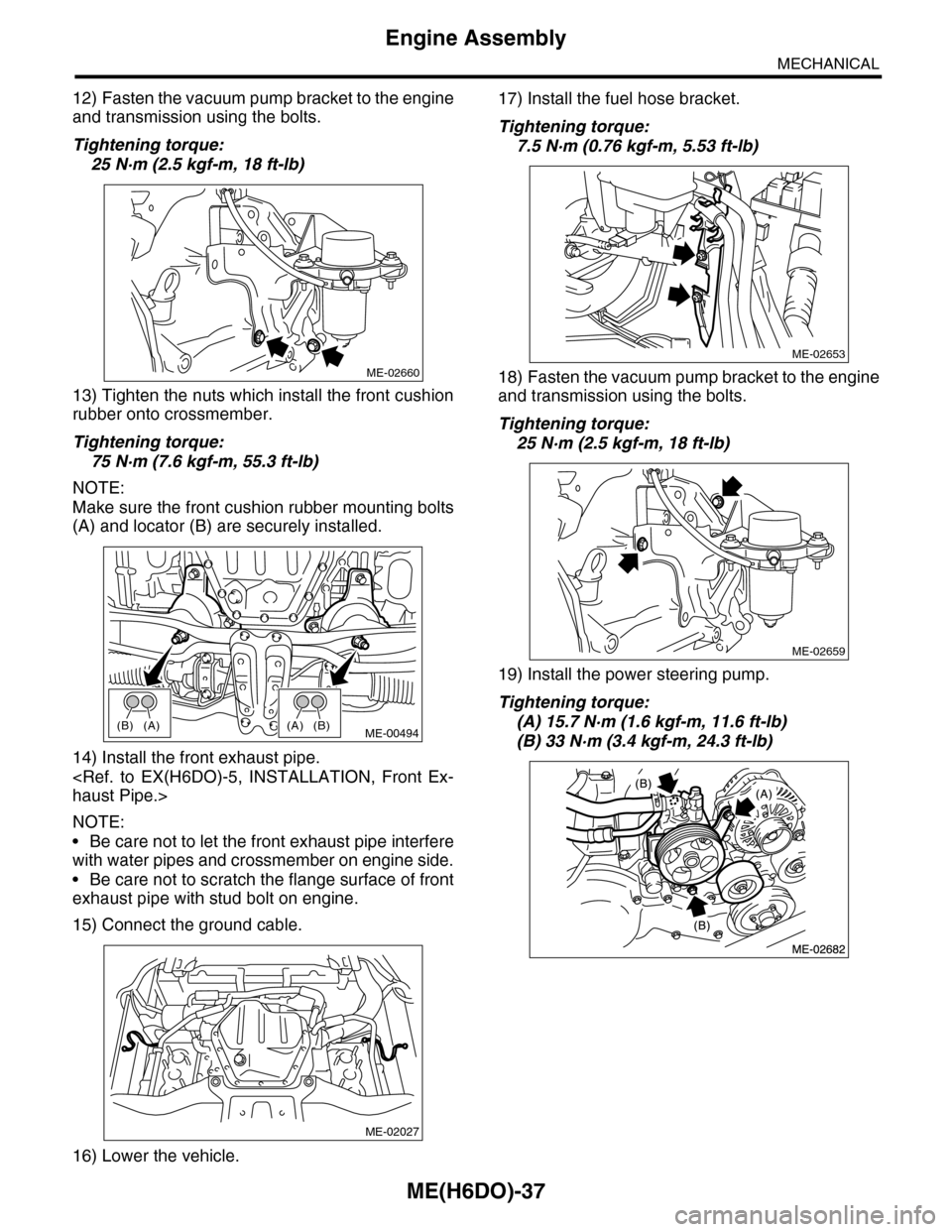
12) Fasten the vacuum pump bracket to the engine
and transmission using the bolts.
Tightening torque:
25 N·m (2.5 kgf-m, 18 ft-lb)
13) Tighten the nuts which install the front cushion
rubber onto crossmember.
Tightening torque:
75 N·m (7.6 kgf-m, 55.3 ft-lb)
NOTE:
Make sure the front cushion rubber mounting bolts
(A) and locator (B) are securely installed.
14) Install the front exhaust pipe.
haust Pipe.>
NOTE:
•Be care not to let the front exhaust pipe interfere
with water pipes and crossmember on engine side.
•Be care not to scratch the flange surface of front
exhaust pipe with stud bolt on engine.
15) Connect the ground cable.
16) Lower the vehicle.
17) Install the fuel hose bracket.
Tightening torque:
7.5 N·m (0.76 kgf-m, 5.53 ft-lb)
18) Fasten the vacuum pump bracket to the engine
and transmission using the bolts.
Tightening torque:
25 N·m (2.5 kgf-m, 18 ft-lb)
19) Install the power steering pump.
Tightening torque:
(A) 15.7 N·m (1.6 kgf-m, 11.6 ft-lb)
(B) 33 N·m (3.4 kgf-m, 24.3 ft-lb)
ME-02660
(A)(B)(B)(A)ME-00494
ME-02027
ME-02653
ME-02659
Page 1928 of 2453
ME(H6DO)-62
Cylinder Block
MECHANICAL
21.Cylinder Block
A: REMOVAL
NOTE:
Before conducting this procedure, drain the engine
oil completely.
1) Remove the crank pulley.
41, REMOVAL, Crank Pulley.>
2) Remove the front chain cover.
ME(H6DO)-42, REMOVAL, Front Chain Cover.>
3) Remove the timing chain assembly.
Assembly.>
4) Remove the cam sprocket.
et.>
5) Remove the crank sprocket.
et.>
6) Remove the rear chain cover.
Cover.>
7) Remove the camshaft.
REMOVAL, Camshaft.>
8) Remove the cylinder head.
57, REMOVAL, Cylinder Head.>
9) Remove the drive plate.
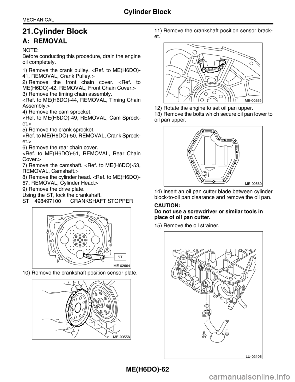
Using the ST, lock the crankshaft.
ST 498497100 CRANKSHAFT STOPPER
10) Remove the crankshaft position sensor plate.
11) Remove the crankshaft position sensor brack-
et.
12) Rotate the engine to set oil pan upper.
13) Remove the bolts which secure oil pan lower to
oil pan upper.
14) Insert an oil pan cutter blade between cylinder
block-to-oil pan clearance and remove the oil pan.
CAUTION:
Do not use a screwdriver or similar tools in
place of oil pan cutter.
15) Remove the oil strainer.
ME-02664
ST
ME-00558
ME-00559
ME-00560
LU-02108
Page 1929 of 2453
ME(H6DO)-63
Cylinder Block
MECHANICAL
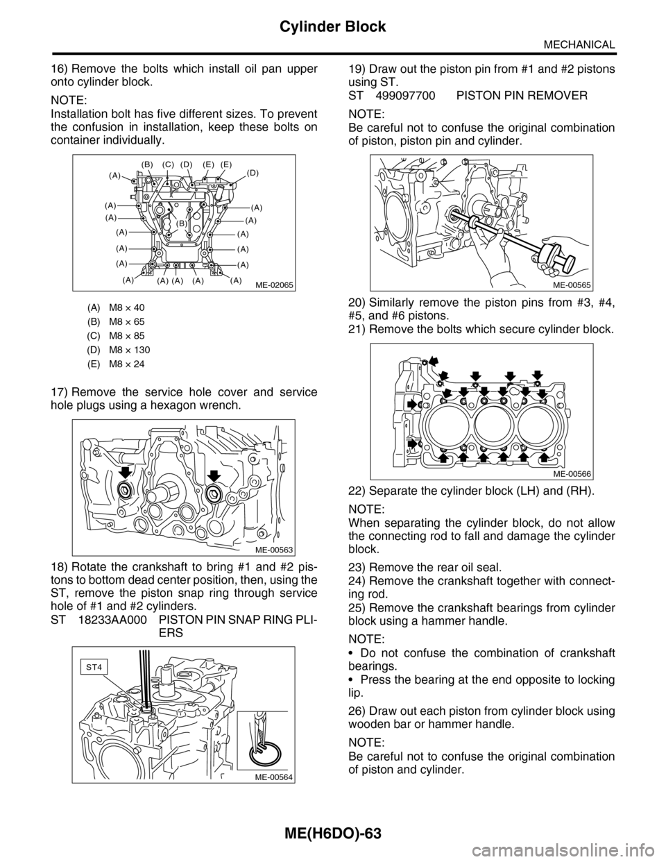
16) Remove the bolts which install oil pan upper
onto cylinder block.
NOTE:
Installation bolt has five different sizes. To prevent
the confusion in installation, keep these bolts on
container individually.
17) Remove the service hole cover and service
hole plugs using a hexagon wrench.
18) Rotate the crankshaft to bring #1 and #2 pis-
tons to bottom dead center position, then, using the
ST, remove the piston snap ring through service
hole of #1 and #2 cylinders.
ST 18233AA000 PISTON PIN SNAP RING PLI-
ERS
19) Draw out the piston pin from #1 and #2 pistons
using ST.
ST 499097700 PISTON PIN REMOVER
NOTE:
Be careful not to confuse the original combination
of piston, piston pin and cylinder.
20) Similarly remove the piston pins from #3, #4,
#5, and #6 pistons.
21) Remove the bolts which secure cylinder block.
22) Separate the cylinder block (LH) and (RH).
NOTE:
When separating the cylinder block, do not allow
the connecting rod to fall and damage the cylinder
block.
23) Remove the rear oil seal.
24) Remove the crankshaft together with connect-
ing rod.
25) Remove the crankshaft bearings from cylinder
block using a hammer handle.
NOTE:
•Do not confuse the combination of crankshaft
bearings.
•Press the bearing at the end opposite to locking
lip.
26) Draw out each piston from cylinder block using
wooden bar or hammer handle.
NOTE:
Be careful not to confuse the original combination
of piston and cylinder.
(A) M8 × 40
(B) M8 × 65
(C) M8 × 85
(D) M8 × 130
(E) M8 × 24
ME-02065
(D)(E)
(A)
(A)
(A)
(A)
(A)
(A)
(A)
(E)
(A)(A)(A)
(C)(B)
(A)
(D)
(A)
(A)
(A)
(A)
(A)
(B)
ME-00563
ST4
ME-00564
ME-00565
ME-00566