Page 2033 of 2453
5AT-17
General Description
AUTOMATIC TRANSMISSION
C: CAUTION
•Wear work clothing, including a cap, protective goggles and protective shoes during operation.
•Remove contamination including dirt and corrosion before removal, installation or disassembly.
•Keep the disassembled parts in order and protect them from dust and dirt.
•Until the oil pan is removed, do not place with the oil pan side facing up to prevent foreign matter from en-
tering the valve body.
•Before removal, installation or disassembly, be sure to clarify the failure. Avoid unnecessary removal, dis-
assembly and replacement.
•When disassembling the case and other light alloy parts, disassemble them by slightly tapping with a plas-
tic hammer. Do not pry apart with screwdrivers or other tools.
•Be careful not to burn yourself, because each part on the vehicle is hot after running.
•Use SUBARU genuine gear oil, grease or the equivalent. Do not mix them with that of another grade or
from other manufacturers.
•Be sure to tighten bolts and nuts to the specified torque.
•Place shop jacks or rigid racks at the specified points.
•Apply gear oil onto sliding or revolution surfaces before installation.
•Replace deformed or damaged snap rings with new parts.
•Before installing O-rings or oil seals, apply sufficient amount of ATF fluid to avoid damage and deforma-
tion.
•Be careful not to incorrectly install or fail to install O-rings, snap rings and other such parts.
•Before securing a part on a vise, place cushioning material such as wood blocks, aluminum plate, or cloth
between the part and the vise.
•Avoid damaging the mating surface of the case.
•Before applying liquid gasket, completely remove the old seal.
D: PREPARATION TOOL
1. SPECIAL TOOL
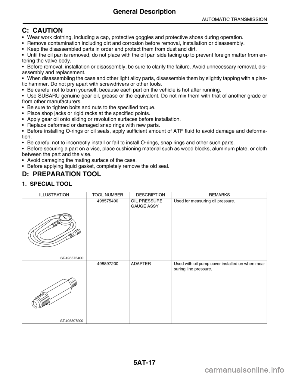
ILLUSTRATION TOOL NUMBER DESCRIPTION REMARKS
498575400 OIL PRESSURE
GAUGE ASSY
Used for measuring oil pressure.
498897200 ADAPTER Used with oil pump cover installed on when mea-
suring line pressure.
ST-498575400
ST-498897200
Page 2050 of 2453
5AT-34
Automatic Transmission Assembly
AUTOMATIC TRANSMISSION
9. Automatic Transmission As-
sembly
A: REMOVAL
1) Set the vehicle on a lift.
2) Open the front hood and support with the hood
stay.
3) Disconnect the ground cable from battery.
4) Remove the collector cover.
5) Remove the air intake chamber.
IN(H6DO)-6, REMOVAL, Air Intake Chamber.>
6) Remove the air breather hose.
REMOVAL, Air Breather Hose.>
7) Remove the starter.
MOVAL, Starter.>
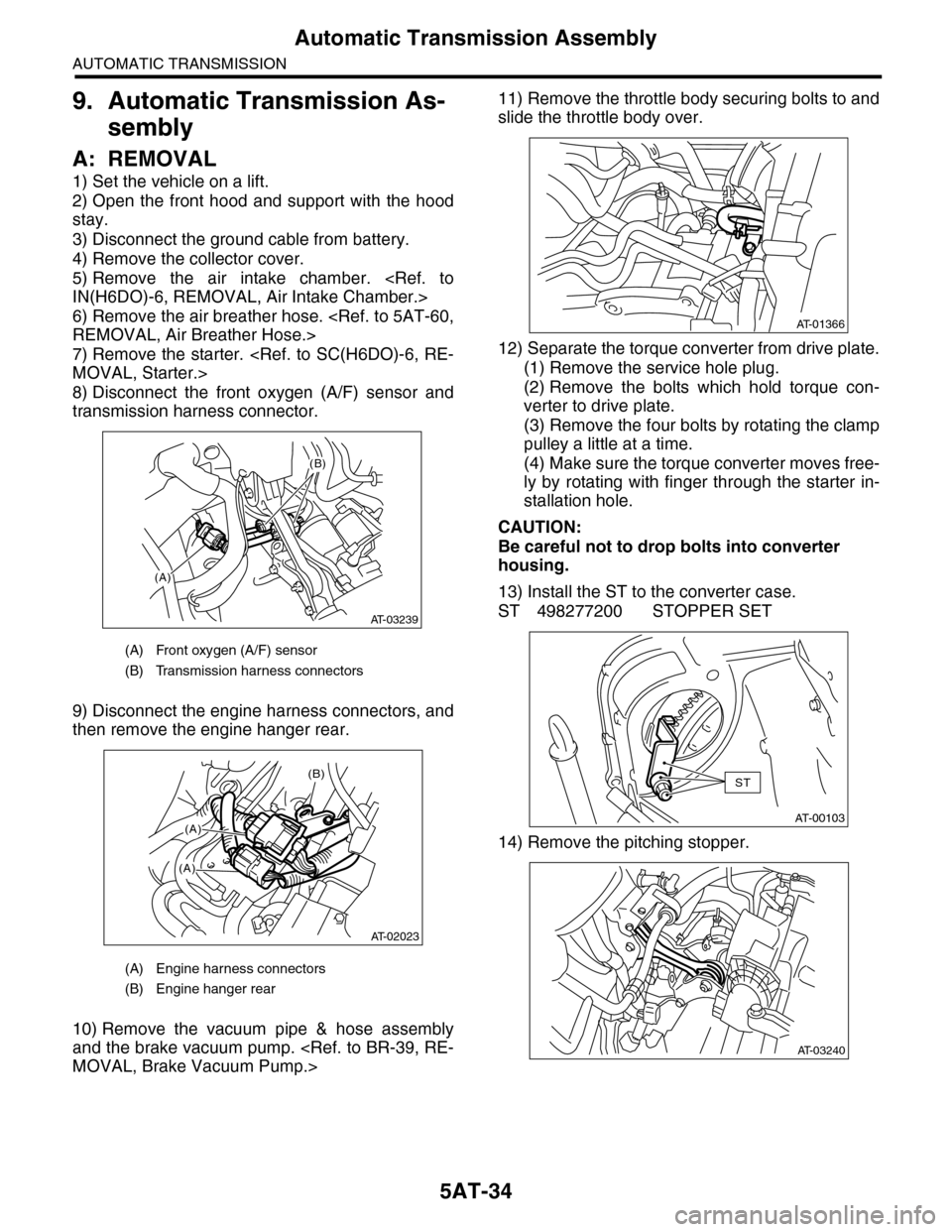
8) Disconnect the front oxygen (A/F) sensor and
transmission harness connector.
9) Disconnect the engine harness connectors, and
then remove the engine hanger rear.
10) Remove the vacuum pipe & hose assembly
and the brake vacuum pump.
MOVAL, Brake Vacuum Pump.>
11) Remove the throttle body securing bolts to and
slide the throttle body over.
12) Separate the torque converter from drive plate.
(1) Remove the service hole plug.
(2) Remove the bolts which hold torque con-
verter to drive plate.
(3) Remove the four bolts by rotating the clamp
pulley a little at a time.
(4) Make sure the torque converter moves free-
ly by rotating with finger through the starter in-
stallation hole.
CAUTION:
Be careful not to drop bolts into converter
housing.
13) Install the ST to the converter case.
ST 498277200 STOPPER SET
14) Remove the pitching stopper.
(A) Front oxygen (A/F) sensor
(B) Transmission harness connectors
(A) Engine harness connectors
(B) Engine hanger rear
(A)
(B)
AT-03239
(B)
(A)
(A)
AT-02023
AT-01366
AT-00103
ST
AT-03240
Page 2052 of 2453
5AT-36
Automatic Transmission Assembly
AUTOMATIC TRANSMISSION
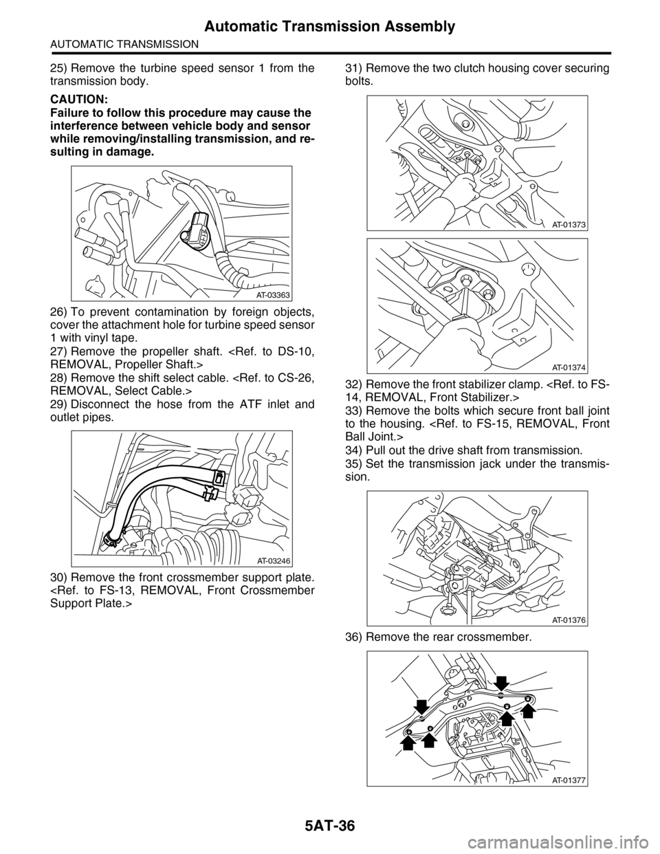
25) Remove the turbine speed sensor 1 from the
transmission body.
CAUTION:
Failure to follow this procedure may cause the
interference between vehicle body and sensor
while removing/installing transmission, and re-
sulting in damage.
26) To prevent contamination by foreign objects,
cover the attachment hole for turbine speed sensor
1 with vinyl tape.
27) Remove the propeller shaft.
REMOVAL, Propeller Shaft.>
28) Remove the shift select cable.
REMOVAL, Select Cable.>
29) Disconnect the hose from the ATF inlet and
outlet pipes.
30) Remove the front crossmember support plate.
Support Plate.>
31) Remove the two clutch housing cover securing
bolts.
32) Remove the front stabilizer clamp.
14, REMOVAL, Front Stabilizer.>
33) Remove the bolts which secure front ball joint
to the housing.
Ball Joint.>
34) Pull out the drive shaft from transmission.
35) Set the transmission jack under the transmis-
sion.
36) Remove the rear crossmember.
AT-03363
AT-03246
AT-01373
AT-01374
AT-01376
AT-01377
Page 2054 of 2453
5AT-38
Automatic Transmission Assembly
AUTOMATIC TRANSMISSION
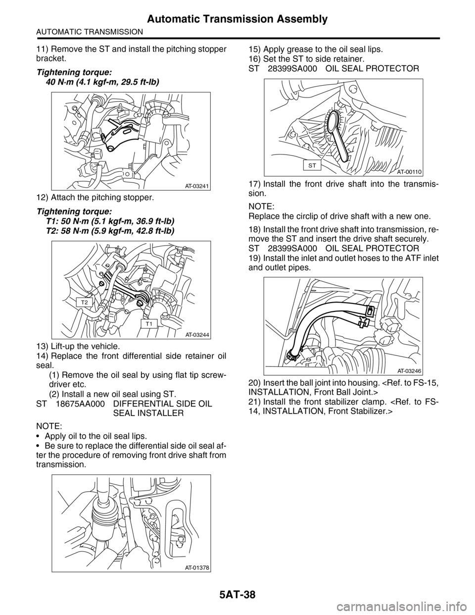
11) Remove the ST and install the pitching stopper
bracket.
Tightening torque:
40 N·m (4.1 kgf-m, 29.5 ft-lb)
12) Attach the pitching stopper.
Tightening torque:
T1: 50 N·m (5.1 kgf-m, 36.9 ft-lb)
T2: 58 N·m (5.9 kgf-m, 42.8 ft-lb)
13) Lift-up the vehicle.
14) Replace the front differential side retainer oil
seal.
(1) Remove the oil seal by using flat tip screw-
driver etc.
(2) Install a new oil seal using ST.
ST 18675AA000 DIFFERENTIAL SIDE OIL
SEAL INSTALLER
NOTE:
•Apply oil to the oil seal lips.
•Be sure to replace the differential side oil seal af-
ter the procedure of removing front drive shaft from
transmission.
15) Apply grease to the oil seal lips.
16) Set the ST to side retainer.
ST 28399SA000 OIL SEAL PROTECTOR
17) Install the front drive shaft into the transmis-
sion.
NOTE:
Replace the circlip of drive shaft with a new one.
18) Install the front drive shaft into transmission, re-
move the ST and insert the drive shaft securely.
ST 28399SA000 OIL SEAL PROTECTOR
19) Install the inlet and outlet hoses to the ATF inlet
and outlet pipes.
20) Insert the ball joint into housing.
INSTALLATION, Front Ball Joint.>
21) Install the front stabilizer clamp.
14, INSTALLATION, Front Stabilizer.>
AT-03241
AT-03244
T1
T2
AT-01378
AT-00110ST
AT-03246
Page 2055 of 2453
5AT-39
Automatic Transmission Assembly
AUTOMATIC TRANSMISSION
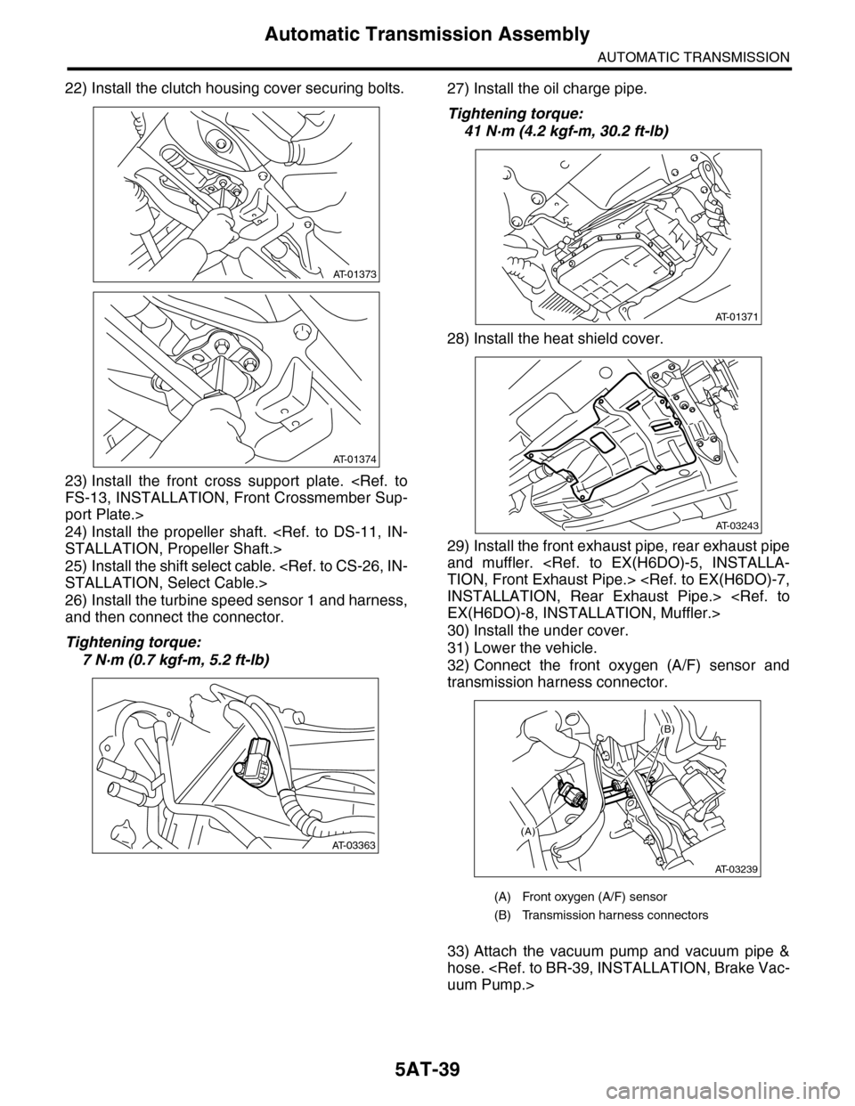
22) Install the clutch housing cover securing bolts.
23) Install the front cross support plate.
FS-13, INSTALLATION, Front Crossmember Sup-
port Plate.>
24) Install the propeller shaft.
STALLATION, Propeller Shaft.>
25) Install the shift select cable.
STALLATION, Select Cable.>
26) Install the turbine speed sensor 1 and harness,
and then connect the connector.
Tightening torque:
7 N·m (0.7 kgf-m, 5.2 ft-lb)
27) Install the oil charge pipe.
Tightening torque:
41 N·m (4.2 kgf-m, 30.2 ft-lb)
28) Install the heat shield cover.
29) Install the front exhaust pipe, rear exhaust pipe
and muffler.
TION, Front Exhaust Pipe.>
INSTALLATION, Rear Exhaust Pipe.>
EX(H6DO)-8, INSTALLATION, Muffler.>
30) Install the under cover.
31) Lower the vehicle.
32) Connect the front oxygen (A/F) sensor and
transmission harness connector.
33) Attach the vacuum pump and vacuum pipe &
hose.
uum Pump.>
AT-01373
AT-01374
AT-03363
(A) Front oxygen (A/F) sensor
(B) Transmission harness connectors
AT-01371
AT-03243
(A)
(B)
AT-03239
Page 2056 of 2453
5AT-40
Automatic Transmission Assembly
AUTOMATIC TRANSMISSION
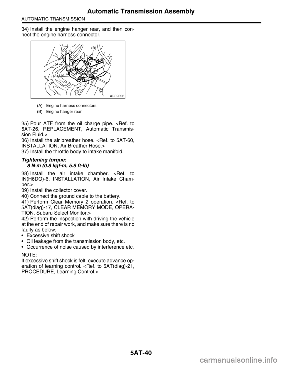
34) Install the engine hanger rear, and then con-
nect the engine harness connector.
35) Pour ATF from the oil charge pipe.
5AT-26, REPLACEMENT, Automatic Transmis-
sion Fluid.>
36) Install the air breather hose.
INSTALLATION, Air Breather Hose.>
37) Install the throttle body to intake manifold.
Tightening torque:
8 N·m (0.8 kgf-m, 5.9 ft-lb)
38) Install the air intake chamber.
IN(H6DO)-6, INSTALLATION, Air Intake Cham-
ber.>
39) Install the collector cover.
40) Connect the ground cable to the battery.
41) Perform Clear Memory 2 operation.
5AT(diag)-17, CLEAR MEMORY MODE, OPERA-
TION, Subaru Select Monitor.>
42) Perform the inspection with driving the vehicle
at the end of repair work, and make sure there is no
faulty as below;
•Excessive shift shock
•Oil leakage from the transmission body, etc.
•Occurrence of noise caused by interference etc.
NOTE:
If excessive shift shock is felt, execute advance op-
eration of learning control.
PROCEDURE, Learning Control.>
(A) Engine harness connectors
(B) Engine hanger rear
(B)
(A)
(A)
AT-02023
Page 2063 of 2453
5AT-47
Front Vehicle Speed Sensor
AUTOMATIC TRANSMISSION
14.Front Vehicle Speed Sensor
A: REMOVAL
1) Remove the transmission assembly from vehicle
body.
Transmission Assembly.>
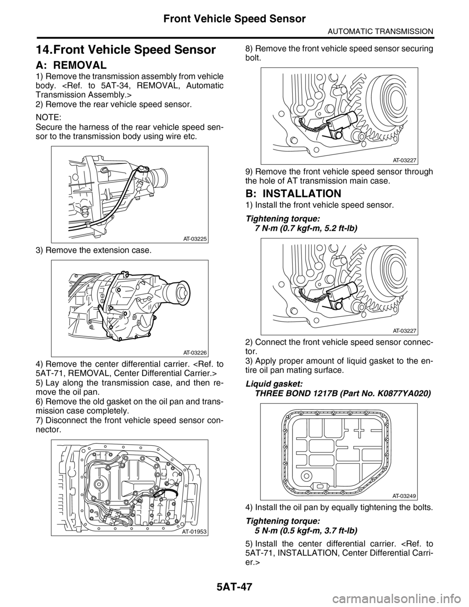
2) Remove the rear vehicle speed sensor.
NOTE:
Secure the harness of the rear vehicle speed sen-
sor to the transmission body using wire etc.
3) Remove the extension case.
4) Remove the center differential carrier.
5AT-71, REMOVAL, Center Differential Carrier.>
5) Lay along the transmission case, and then re-
move the oil pan.
6) Remove the old gasket on the oil pan and trans-
mission case completely.
7) Disconnect the front vehicle speed sensor con-
nector.
8) Remove the front vehicle speed sensor securing
bolt.
9) Remove the front vehicle speed sensor through
the hole of AT transmission main case.
B: INSTALLATION
1) Install the front vehicle speed sensor.
Tightening torque:
7 N·m (0.7 kgf-m, 5.2 ft-lb)
2) Connect the front vehicle speed sensor connec-
tor.
3) Apply proper amount of liquid gasket to the en-
tire oil pan mating surface.
Liquid gasket:
THREE BOND 1217B (Part No. K0877YA020)
4) Install the oil pan by equally tightening the bolts.
Tightening torque:
5 N·m (0.5 kgf-m, 3.7 ft-lb)
5) Install the center differential carrier.
5AT-71, INSTALLATION, Center Differential Carri-
er.>
AT-03225
AT-03226
AT-01953
AT-03227
AT-03227
AT-03249
Page 2066 of 2453
5AT-50
Rear Vehicle Speed Sensor
AUTOMATIC TRANSMISSION
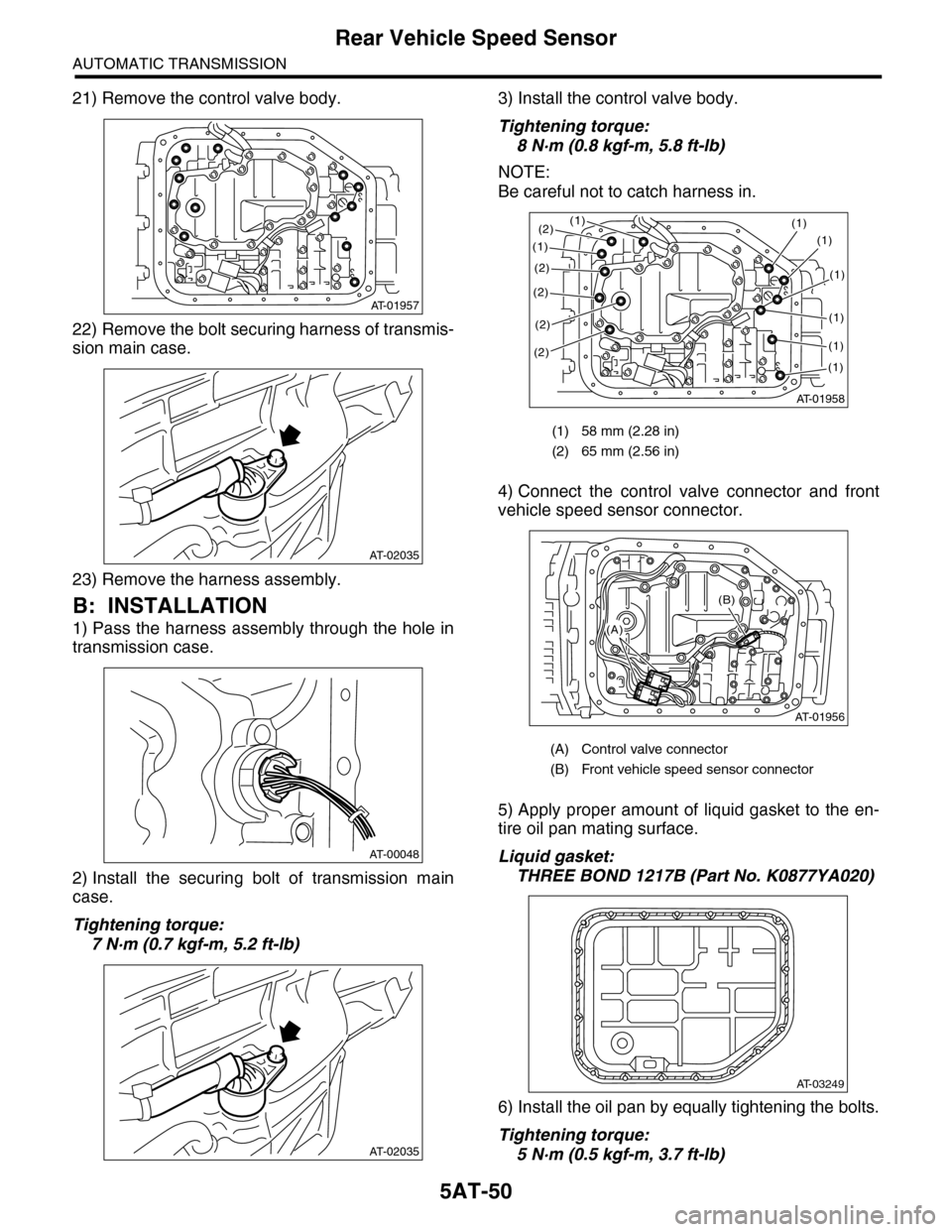
21) Remove the control valve body.
22) Remove the bolt securing harness of transmis-
sion main case.
23) Remove the harness assembly.
B: INSTALLATION
1) Pass the harness assembly through the hole in
transmission case.
2) Install the securing bolt of transmission main
case.
Tightening torque:
7 N·m (0.7 kgf-m, 5.2 ft-lb)
3) Install the control valve body.
Tightening torque:
8 N·m (0.8 kgf-m, 5.8 ft-lb)
NOTE:
Be careful not to catch harness in.
4) Connect the control valve connector and front
vehicle speed sensor connector.
5) Apply proper amount of liquid gasket to the en-
tire oil pan mating surface.
Liquid gasket:
THREE BOND 1217B (Part No. K0877YA020)
6) Install the oil pan by equally tightening the bolts.
Tightening torque:
5 N·m (0.5 kgf-m, 3.7 ft-lb)
AT-01957
AT-02035
AT-00048
AT-02035
(1) 58 mm (2.28 in)
(2) 65 mm (2.56 in)
(A) Control valve connector
(B) Front vehicle speed sensor connector
AT-01958
(1)(1)
(1)
(2)
(2)
(2)
(2)
(1)
(1)
(1)
(1)
(1)
(2)
AT-01956
(B)
(A)
AT-03249