2009 SUBARU TRIBECA ECU
[x] Cancel search: ECUPage 2143 of 2453
5AT(diag)-26
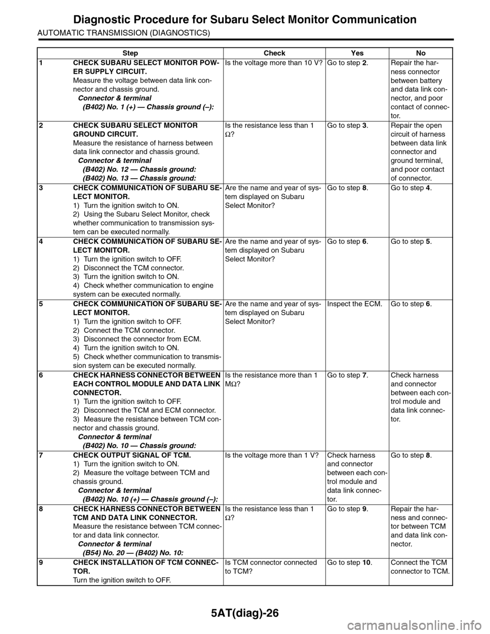
Diagnostic Procedure for Subaru Select Monitor Communication
AUTOMATIC TRANSMISSION (DIAGNOSTICS)
Step Check Yes No
1CHECK SUBARU SELECT MONITOR POW-
ER SUPPLY CIRCUIT.
Measure the voltage between data link con-
nector and chassis ground.
Connector & terminal
(B402) No. 1 (+) — Chassis ground (–):
Is the voltage more than 10 V? Go to step 2.Repair the har-
ness connector
between battery
and data link con-
nector, and poor
contact of connec-
tor.
2CHECK SUBARU SELECT MONITOR
GROUND CIRCUIT.
Measure the resistance of harness between
data link connector and chassis ground.
Connector & terminal
(B402) No. 12 — Chassis ground:
(B402) No. 13 — Chassis ground:
Is the resistance less than 1
Ω?
Go to step 3.Repair the open
circuit of harness
between data link
connector and
ground terminal,
and poor contact
of connector.
3CHECK COMMUNICATION OF SUBARU SE-
LECT MONITOR.
1) Turn the ignition switch to ON.
2) Using the Subaru Select Monitor, check
whether communication to transmission sys-
tem can be executed normally.
Are the name and year of sys-
tem displayed on Subaru
Select Monitor?
Go to step 8.Go to step 4.
4CHECK COMMUNICATION OF SUBARU SE-
LECT MONITOR.
1) Turn the ignition switch to OFF.
2) Disconnect the TCM connector.
3) Turn the ignition switch to ON.
4) Check whether communication to engine
system can be executed normally.
Are the name and year of sys-
tem displayed on Subaru
Select Monitor?
Go to step 6.Go to step 5.
5CHECK COMMUNICATION OF SUBARU SE-
LECT MONITOR.
1) Turn the ignition switch to OFF.
2) Connect the TCM connector.
3) Disconnect the connector from ECM.
4) Turn the ignition switch to ON.
5) Check whether communication to transmis-
sion system can be executed normally.
Are the name and year of sys-
tem displayed on Subaru
Select Monitor?
Inspect the ECM. Go to step 6.
6CHECK HARNESS CONNECTOR BETWEEN
EACH CONTROL MODULE AND DATA LINK
CONNECTOR.
1) Turn the ignition switch to OFF.
2) Disconnect the TCM and ECM connector.
3) Measure the resistance between TCM con-
nector and chassis ground.
Connector & terminal
(B402) No. 10 — Chassis ground:
Is the resistance more than 1
MΩ?
Go to step 7.Check harness
and connector
between each con-
trol module and
data link connec-
tor.
7CHECK OUTPUT SIGNAL OF TCM.
1) Turn the ignition switch to ON.
2) Measure the voltage between TCM and
chassis ground.
Connector & terminal
(B402) No. 10 (+) — Chassis ground (–):
Is the voltage more than 1 V? Check harness
and connector
between each con-
trol module and
data link connec-
tor.
Go to step 8.
8CHECK HARNESS CONNECTOR BETWEEN
TCM AND DATA LINK CONNECTOR.
Measure the resistance between TCM connec-
tor and data link connector.
Connector & terminal
(B54) No. 20 — (B402) No. 10:
Is the resistance less than 1
Ω?
Go to step 9.Repair the har-
ness and connec-
tor between TCM
and data link con-
nector.
9CHECK INSTALLATION OF TCM CONNEC-
TOR.
Tu r n t h e i g n i t i o n s w i t c h t o O F F.
Is TCM connector connected
to TCM?
Go to step 10.Connect the TCM
connector to TCM.
Page 2159 of 2453
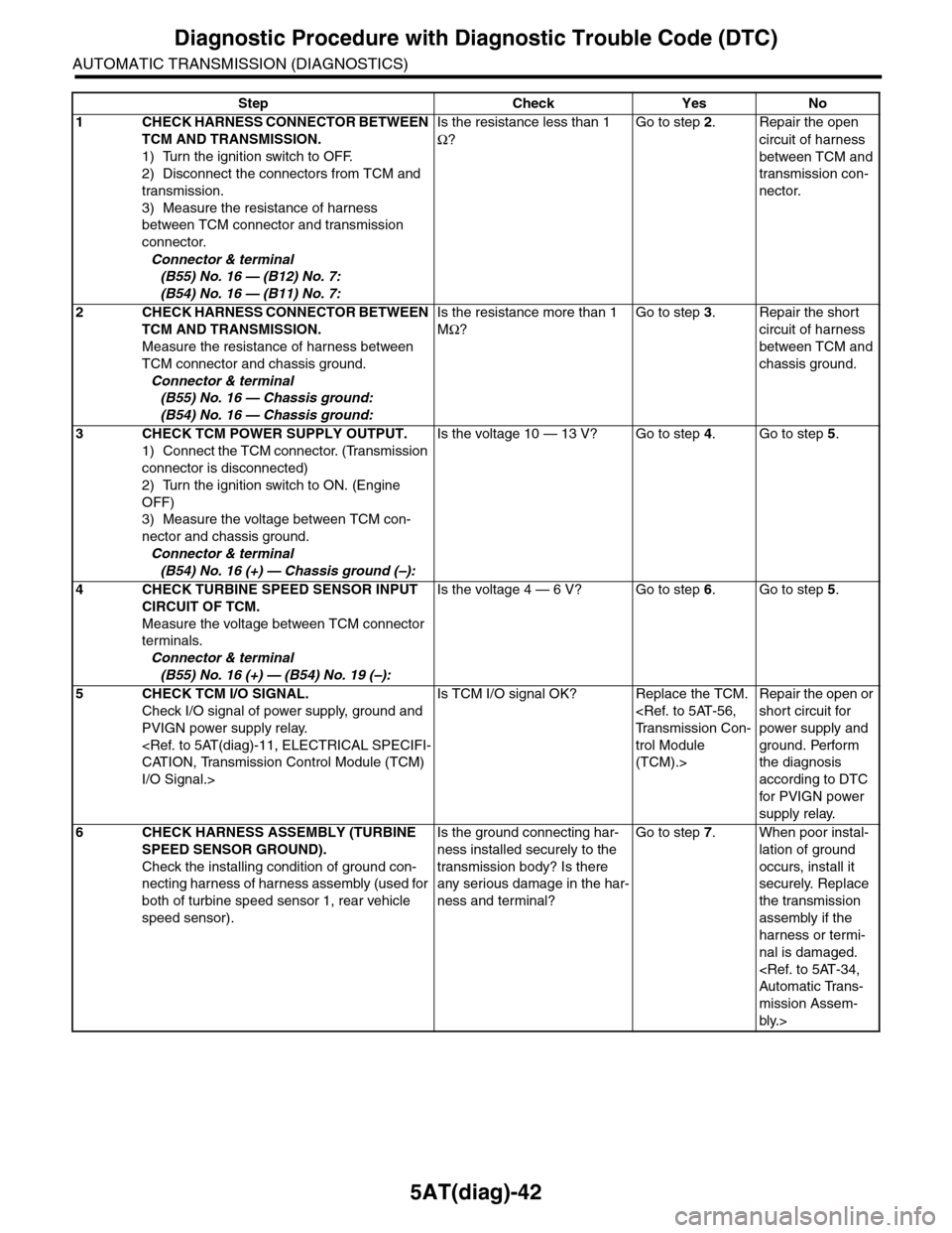
5AT(diag)-42
Diagnostic Procedure with Diagnostic Trouble Code (DTC)
AUTOMATIC TRANSMISSION (DIAGNOSTICS)
Step Check Yes No
1CHECK HARNESS CONNECTOR BETWEEN
TCM AND TRANSMISSION.
1) Turn the ignition switch to OFF.
2) Disconnect the connectors from TCM and
transmission.
3) Measure the resistance of harness
between TCM connector and transmission
connector.
Connector & terminal
(B55) No. 16 — (B12) No. 7:
(B54) No. 16 — (B11) No. 7:
Is the resistance less than 1
Ω?
Go to step 2.Repair the open
circuit of harness
between TCM and
transmission con-
nector.
2CHECK HARNESS CONNECTOR BETWEEN
TCM AND TRANSMISSION.
Measure the resistance of harness between
TCM connector and chassis ground.
Connector & terminal
(B55) No. 16 — Chassis ground:
(B54) No. 16 — Chassis ground:
Is the resistance more than 1
MΩ?
Go to step 3.Repair the short
circuit of harness
between TCM and
chassis ground.
3CHECK TCM POWER SUPPLY OUTPUT.
1) Connect the TCM connector. (Transmission
connector is disconnected)
2) Turn the ignition switch to ON. (Engine
OFF)
3) Measure the voltage between TCM con-
nector and chassis ground.
Connector & terminal
(B54) No. 16 (+) — Chassis ground (–):
Is the voltage 10 — 13 V? Go to step 4.Go to step 5.
4CHECK TURBINE SPEED SENSOR INPUT
CIRCUIT OF TCM.
Measure the voltage between TCM connector
terminals.
Connector & terminal
(B55) No. 16 (+) — (B54) No. 19 (–):
Is the voltage 4 — 6 V? Go to step 6.Go to step 5.
5CHECK TCM I/O SIGNAL.
Check I/O signal of power supply, ground and
PVIGN power supply relay.
I/O Signal.>
Is TCM I/O signal OK? Replace the TCM.
trol Module
(TCM).>
Repair the open or
short circuit for
power supply and
ground. Perform
the diagnosis
according to DTC
for PVIGN power
supply relay.
6CHECK HARNESS ASSEMBLY (TURBINE
SPEED SENSOR GROUND).
Check the installing condition of ground con-
necting harness of harness assembly (used for
both of turbine speed sensor 1, rear vehicle
speed sensor).
Is the ground connecting har-
ness installed securely to the
transmission body? Is there
any serious damage in the har-
ness and terminal?
Go to step 7.When poor instal-
lation of ground
occurs, install it
securely. Replace
the transmission
assembly if the
harness or termi-
nal is damaged.
mission Assem-
bly.>
Page 2216 of 2453
5AT(diag)-99
Diagnostic Procedure with Diagnostic Trouble Code (DTC)
AUTOMATIC TRANSMISSION (DIAGNOSTICS)
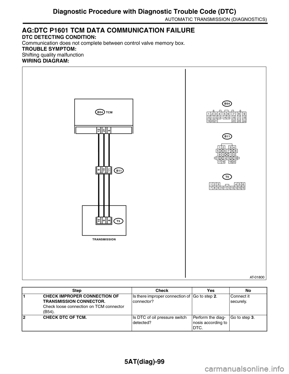
AG:DTC P1601 TCM DATA COMMUNICATION FAILURE
DTC DETECTING CONDITION:
Communication does not complete between control valve memory box.
TROUBLE SYMPTOM:
Shifting quality malfunction
WIRING DIAGRAM:
AT-01800
B54TCM
B54
12789563410 11 1219 20 2113 14 15 16 17 18222324
B11
125678
131415169101112
34
17181920
6
B11
1221
11910
T58109
123 68910 11 12 13 14451516
T5
7
TRANSMISSION
Step Check Yes No
1CHECK IMPROPER CONNECTION OF
TRANSMISSION CONNECTOR.
Check loose connection on TCM connector
(B54).
Is there improper connection of
connector?
Go to step 2.Connect it
securely.
2CHECK DTC OF TCM.Is DTC of oil pressure switch
detected?
Pe r for m t h e d ia g -
nosis according to
DTC.
Go to step 3.
Page 2219 of 2453
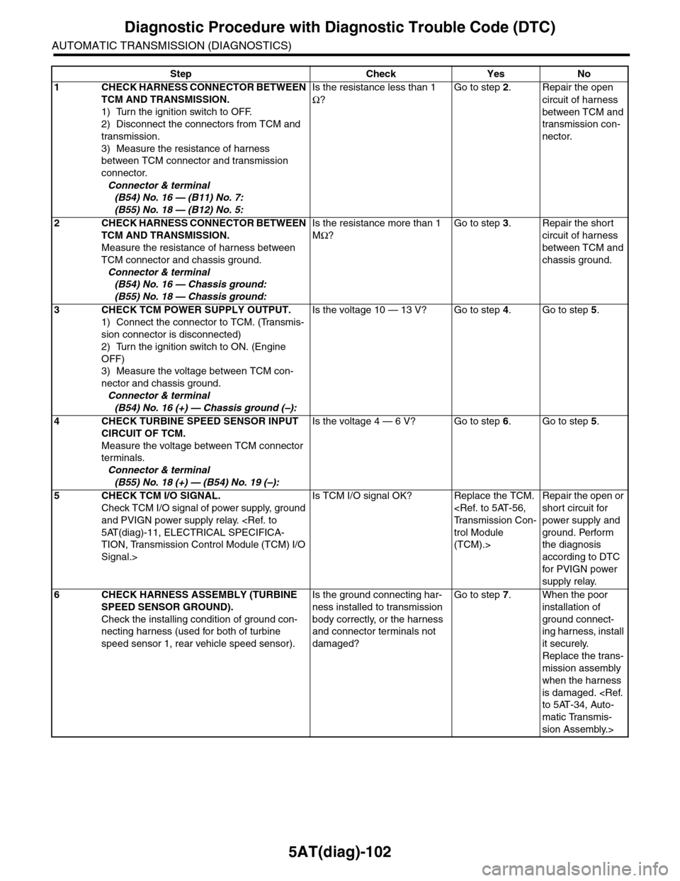
5AT(diag)-102
Diagnostic Procedure with Diagnostic Trouble Code (DTC)
AUTOMATIC TRANSMISSION (DIAGNOSTICS)
Step Check Yes No
1CHECK HARNESS CONNECTOR BETWEEN
TCM AND TRANSMISSION.
1) Turn the ignition switch to OFF.
2) Disconnect the connectors from TCM and
transmission.
3) Measure the resistance of harness
between TCM connector and transmission
connector.
Connector & terminal
(B54) No. 16 — (B11) No. 7:
(B55) No. 18 — (B12) No. 5:
Is the resistance less than 1
Ω?
Go to step 2.Repair the open
circuit of harness
between TCM and
transmission con-
nector.
2CHECK HARNESS CONNECTOR BETWEEN
TCM AND TRANSMISSION.
Measure the resistance of harness between
TCM connector and chassis ground.
Connector & terminal
(B54) No. 16 — Chassis ground:
(B55) No. 18 — Chassis ground:
Is the resistance more than 1
MΩ?
Go to step 3.Repair the short
circuit of harness
between TCM and
chassis ground.
3CHECK TCM POWER SUPPLY OUTPUT.
1) Connect the connector to TCM. (Transmis-
sion connector is disconnected)
2) Turn the ignition switch to ON. (Engine
OFF)
3) Measure the voltage between TCM con-
nector and chassis ground.
Connector & terminal
(B54) No. 16 (+) — Chassis ground (–):
Is the voltage 10 — 13 V? Go to step 4.Go to step 5.
4CHECK TURBINE SPEED SENSOR INPUT
CIRCUIT OF TCM.
Measure the voltage between TCM connector
terminals.
Connector & terminal
(B55) No. 18 (+) — (B54) No. 19 (–):
Is the voltage 4 — 6 V? Go to step 6.Go to step 5.
5CHECK TCM I/O SIGNAL.
Check TCM I/O signal of power supply, ground
and PVIGN power supply relay.
TION, Transmission Control Module (TCM) I/O
Signal.>
Is TCM I/O signal OK? Replace the TCM.
trol Module
(TCM).>
Repair the open or
short circuit for
power supply and
ground. Perform
the diagnosis
according to DTC
for PVIGN power
supply relay.
6CHECK HARNESS ASSEMBLY (TURBINE
SPEED SENSOR GROUND).
Check the installing condition of ground con-
necting harness (used for both of turbine
speed sensor 1, rear vehicle speed sensor).
Is the ground connecting har-
ness installed to transmission
body correctly, or the harness
and connector terminals not
damaged?
Go to step 7.When the poor
installation of
ground connect-
ing harness, install
it securely.
Replace the trans-
mission assembly
when the harness
is damaged.
matic Transmis-
sion Assembly.>
Page 2256 of 2453
CS-4
General Description
CONTROL SYSTEMS
C: CAUTION
•Wear work clothing, including a cap, protective
goggles and protective shoes during operation.
•Remove contamination including dirt and corro-
sion before removal, installation or disassembly.
•Keep the disassembled parts in order and pro-
tect them from dust and dirt.
•Before removal, installation or disassembly, be
sure to clarify the failure. Avoid unnecessary re-
moval, installation, disassembly and replacement.
•Use SUBARU genuine fluid, grease etc. or
equivalent. Do not mix fluid, grease, etc. with that of
another grade or from other manufacturers.
•Be sure to tighten fasteners including bolts and
nuts to the specified torque.
•Place shop jacks or rigid racks at the specified
points.
•Apply grease onto sliding or revolution surfaces
before installation.
•Before installing O-rings or snap rings, apply suf-
ficient amount of fluid to avoid damage and defor-
mation.
•Before securing a part in a vise, place cushioning
material such as wood blocks, aluminum plate or
cloth between the part and the vise.
•Before disconnecting electrical connectors, be
sure to disconnect the negative terminal from bat-
tery.
Page 2272 of 2453
CS-20
Select Lever
CONTROL SYSTEMS
3) Install the shift select cable onto select lever.
4) Install the center console.
5) Install the console box.
6) Shift the select lever to “N” range.
7) Lift–up the vehicle.
8) Shift the range select lever to the “N” range.
9) Secure the cable to the bracket.
10) Adjust the select cable position.
11) After the completion of adjustment, confirm that
the select lever operates properly at all range posi-
tions.
12) Install the heat shield cover.
13) Install the rear exhaust pipe and muffler.
Pipe.>
14) Inspect the following items. When a malfunc-
tion is found in the inspection, adjust the select ca-
ble.
(1) Engine starts when the select lever is in “P”
and “N” range, but not in other ranges.
(2) Back-up light illuminates when the select le-
ver is in the “R” range, but not in other ranges.
(3) Select lever and indicator positions are
matched.
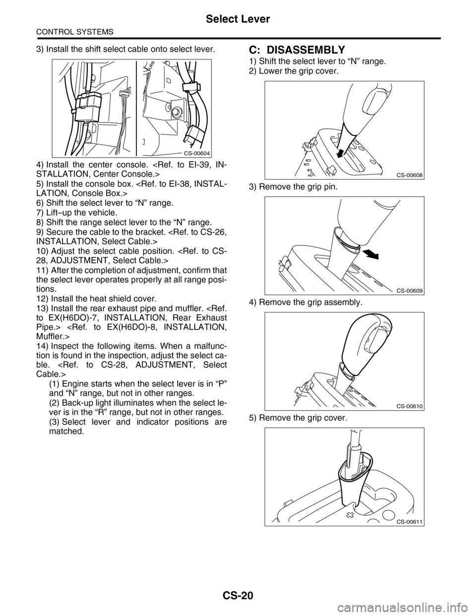
C: DISASSEMBLY
1) Shift the select lever to “N” range.
2) Lower the grip cover.
3) Remove the grip pin.
4) Remove the grip assembly.
5) Remove the grip cover.
CS-00604
CS-00608
CS-00609
CS-00610
CS-00611
Page 2291 of 2453
WI-7
Basic Diagnostic Procedure
WIRING SYSTEM
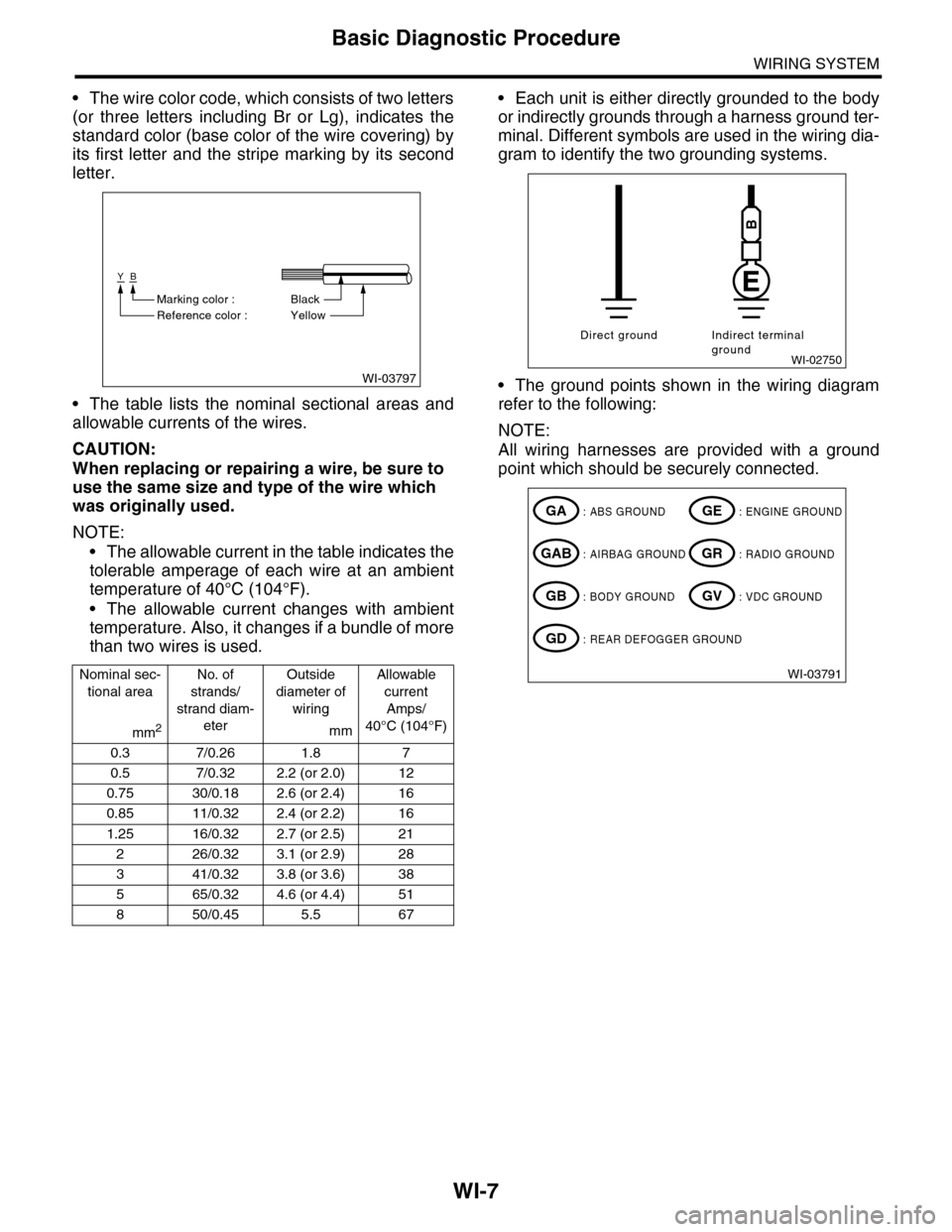
•The wire color code, which consists of two letters
(or three letters including Br or Lg), indicates the
standard color (base color of the wire covering) by
its first letter and the stripe marking by its second
letter.
•The table lists the nominal sectional areas and
allowable currents of the wires.
CAUTION:
When replacing or repairing a wire, be sure to
use the same size and type of the wire which
was originally used.
NOTE:
•The allowable current in the table indicates the
tolerable amperage of each wire at an ambient
temperature of 40°C (104°F).
•The allowable current changes with ambient
temperature. Also, it changes if a bundle of more
than two wires is used.
•Each unit is either directly grounded to the body
or indirectly grounds through a harness ground ter-
minal. Different symbols are used in the wiring dia-
gram to identify the two grounding systems.
•The ground points shown in the wiring diagram
refer to the following:
NOTE:
All wiring harnesses are provided with a ground
point which should be securely connected.
Nominal sec-
tional area
No. of
strands/
strand diam-
eter
Outside
diameter of
wiring
Allowable
current
Amps/
40°C (104°F)mm2mm
0.3 7/0.26 1.8 7
0.5 7/0.32 2.2 (or 2.0) 12
0.75 30/0.18 2.6 (or 2.4) 16
0.85 11/0.32 2.4 (or 2.2) 16
1.25 16/0.32 2.7 (or 2.5) 21
226/0.323.1 (or 2.9)28
341/0.323.8 (or 3.6)38
565/0.324.6 (or 4.4)51
850/0.455.5 67
WI-03797
YB
BlackMarking color :
Reference color : Yellow
WI-02750
Direct ground Indirect terminalground
B
WI-03791
: ABS GROUNDGA
: AIRBAG GROUNDGAB
: BODY GROUNDGB
: ENGINE GROUNDGE
: RADIO GROUNDGR
: VDC GROUNDGV
: REAR DEFOGGER GROUNDGD
Page 2298 of 2453
WI-14
Working Precautions
WIRING SYSTEM
2. Working Precautions
A: PRECAUTIONS WHEN WORKING
WITH THE PARTS MOUNTED ON
THE VEHICLE
1) When working under a vehicle which is jacked-
up, always be sure to use rigid rack.
2) The parking brake must always be applied dur-
ing working. Also, in automatic transmission vehi-
cles, keep the select lever set to the P (Parking)
range.
3) Be sure the workshop is properly ventilated
when running the engine. Further, be careful not to
touch the belt or fan while the engine is operating.
4) Be careful not to touch hot metal parts, especial-
ly the radiator and exhaust system immediately af-
ter the engine has been turned off.
B: PRECAUTIONS IN TROUBLE DI-
AGNOSIS AND REPAIR OF ELEC-
TRIC PARTS
1) The battery cable must be disconnected from
the battery’s (–) terminal, and the ignition switch
must be set to the OFF position, unless otherwise
required by the diagnostics.
2) Securely fasten the wiring harness with clamps
and slips so that the harness does not interfere with
the body end parts or edges and bolts or screws.
3) When installing parts, be careful not to catch
them on the wiring harness.
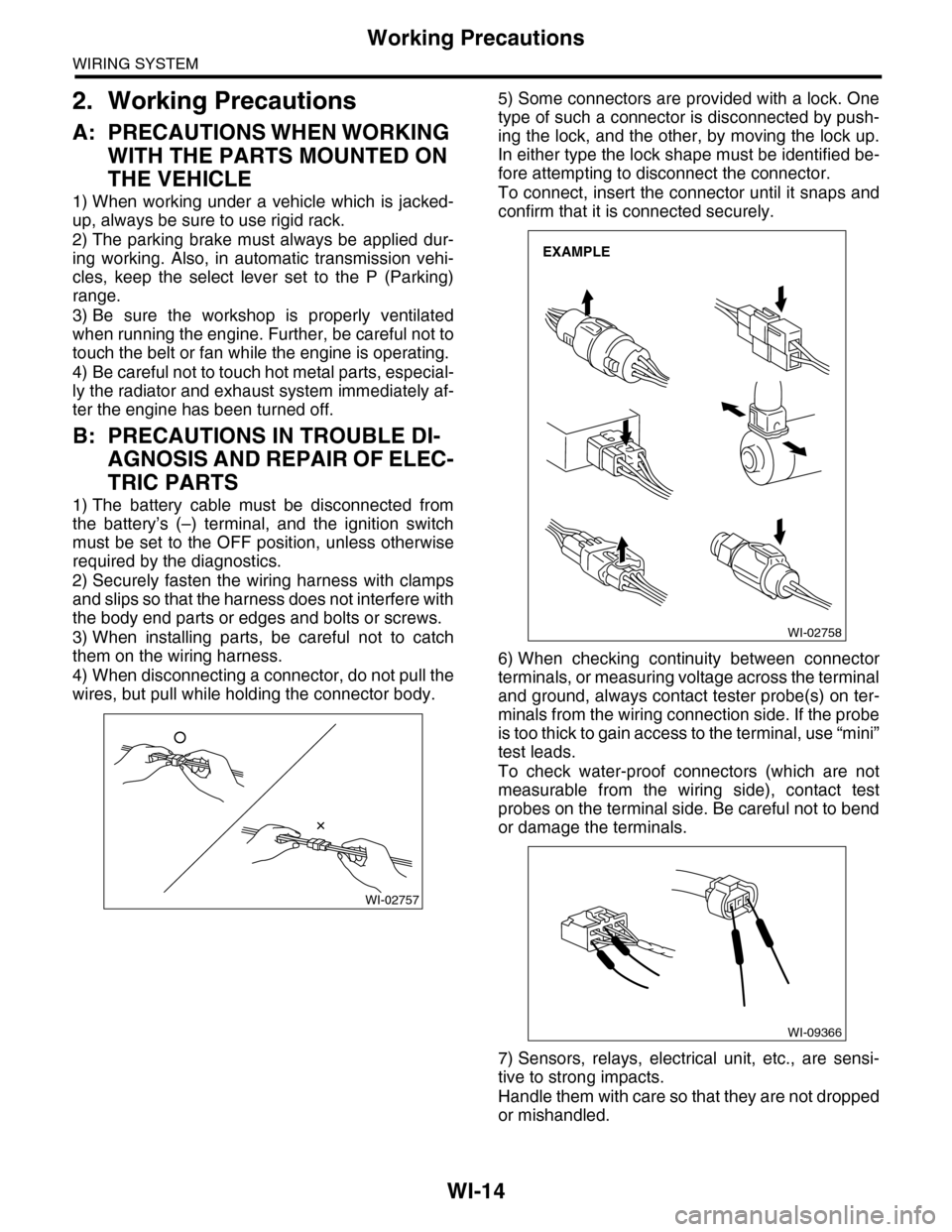
4) When disconnecting a connector, do not pull the
wires, but pull while holding the connector body.
5) Some connectors are provided with a lock. One
type of such a connector is disconnected by push-
ing the lock, and the other, by moving the lock up.
In either type the lock shape must be identified be-
fore attempting to disconnect the connector.
To connect, insert the connector until it snaps and
confirm that it is connected securely.
6) When checking continuity between connector
terminals, or measuring voltage across the terminal
and ground, always contact tester probe(s) on ter-
minals from the wiring connection side. If the probe
is too thick to gain access to the terminal, use “mini”
test leads.
To check water-proof connectors (which are not
measurable from the wiring side), contact test
probes on the terminal side. Be careful not to bend
or damage the terminals.
7) Sensors, relays, electrical unit, etc., are sensi-
tive to strong impacts.
Handle them with care so that they are not dropped
or mishandled.
WI-02757
WI-02758
EXAMPLE
WI-09366