Page 160 of 2453
COM-3
Horn System
COMMUNICATION SYSTEM
2. Horn System
A: WIRING DIAGRAM
1. HORN
tem.>
B: INSPECTION
1. HORN RELAY
Measure the security horn relay resistance be-
tween terminals (indicated in the table below) when
connecting terminal No. 4 to battery positive termi-
nal and terminal No. 3 to battery ground terminal.
Current Terminal No. Standard
Ye s1 and 2Less than 1 Ω
No 1 MΩ or more
COM00001
(1)(2)
(1)
(4)
(2)
(3)
(3)(4)
Page 165 of 2453
CC-3
General Description
CRUISE CONTROL SYSTEM
B: CAUTION
•Before disassembling or reassembling parts, al-
ways disconnect the battery ground cable from bat-
tery. When repairing the audio, control module, etc.
which are provided with memory functions, record
the memory contents before disconnecting the
ground cable from battery. Otherwise, the memory
will be cleared.
•Reassemble the parts in the reverse order of dis-
assembly unless otherwise indicated.
•Adjust the parts to specifications specified in this
manual.
•Connect the connectors securely during reas-
sembly.
•After reassembly, ensure functional parts oper-
ate properly.
C: PREPARATION TOOL
TOOL NAME REMARKS
Circuit tester Used for measuring resis-
tance and voltage.
Page 167 of 2453

CC-5
Cruise Control Command Switch
CRUISE CONTROL SYSTEM
3. Cruise Control Command
Switch
A: REMOVAL
CAUTION:
Before servicing, be sure to read the notes in
the “AB” section for proper handling of the
driver’s airbag module.
TION, General Description.>
1) Set the front wheels in straight ahead position.
2) Turn the ignition switch to OFF.
3) Disconnect the ground cable from battery and
wait for at least 20 seconds before starting work.
4) Using TORX® BIT T30 (1), loosen two TORX®
bolts which secure the driver’s airbag module.
5) Disconnect the airbag module connector on
back of the airbag module.
6) Remove the steering wheel.
MOVAL, Steering Wheel.>
7) Remove the four screws to remove the lower
cover from steering wheel.
8) Remove one screw to remove the cruise control
command switch from lower cover.
B: INSTALLATION
Install in the reverse order of removal.
C: INSPECTION
Measure the cruise control command switch resis-
tance.
If NG, replace the cruise control command switch.
CC-00018
(1)
CC-00181
Switch Area Terminal No. Standard
CANCEL
SET/COAST
RESUME/
ACCEL
All OFF 2 and 3 Approx. 4 kΩ
CANCEL ON 2 and 3 Less than 1 Ω
SET/COAST ON 2 and 3Approximately
250 Ω
RESUME/
ACCELON 2 and 3Approximately
1500 Ω
MAINOFF 1 and 2 1 MΩ or more
ON 1 and 2 Less than 1 Ω
CC-00182
CC-00252
231
Page 188 of 2453
ET-2
General Description
ENTERTAINMENT
1. General Description
A: CAUTION
•Before disassembling or reassembling parts, al-
ways disconnect the battery ground cable from bat-
tery.
•When replacing the audio, control module and
other parts provided with memory functions, record
the memory contents before disconnecting the bat-
tery ground cable. Otherwise, the memory is
cleared.
•Reassemble the parts in the reverse order of dis-
assembly procedure unless otherwise indicated.
•Adjust parts to the given specifications.
•Connect the connectors securely during reas-
sembly.
•After reassembly, make sure functional parts op-
erate smoothly.
B: PREPARATION TOOL
1. GENERAL TOOL
TOOL NAME REMARKS
Circuit Tester Used for measuring resis-
tance and voltage.
Conductive silver composition
(DUPONT No. 4817 or equiv-
alent)
Used for repairing antenna
wire.
Page 241 of 2453

EB-22
Rear Gate
EXTERIOR BODY PANELS
8. Rear Gate
A: REMOVAL
1. REAR GATE PANEL
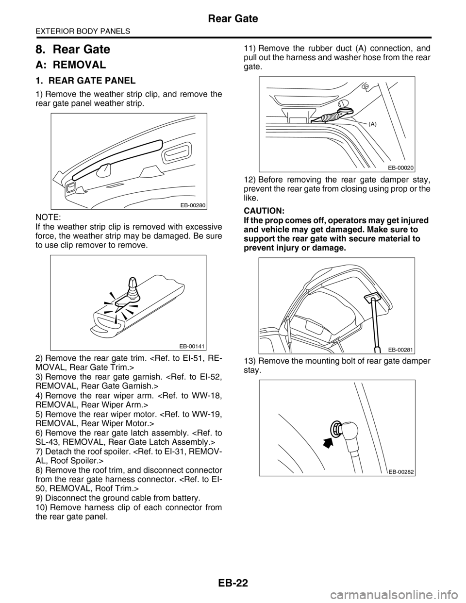
1) Remove the weather strip clip, and remove the
rear gate panel weather strip.
NOTE:
If the weather strip clip is removed with excessive
force, the weather strip may be damaged. Be sure
to use clip remover to remove.
2) Remove the rear gate trim.
MOVAL, Rear Gate Trim.>
3) Remove the rear gate garnish.
REMOVAL, Rear Gate Garnish.>
4) Remove the rear wiper arm.
REMOVAL, Rear Wiper Arm.>
5) Remove the rear wiper motor.
REMOVAL, Rear Wiper Motor.>
6) Remove the rear gate latch assembly.
SL-43, REMOVAL, Rear Gate Latch Assembly.>
7) Detach the roof spoiler.
AL, Roof Spoiler.>
8) Remove the roof trim, and disconnect connector
from the rear gate harness connector.
50, REMOVAL, Roof Trim.>
9) Disconnect the ground cable from battery.
10) Remove harness clip of each connector from
the rear gate panel.
11) Remove the rubber duct (A) connection, and
pull out the harness and washer hose from the rear
gate.
12) Before removing the rear gate damper stay,
prevent the rear gate from closing using prop or the
like.
CAUTION:
If the prop comes off, operators may get injured
and vehicle may get damaged. Make sure to
support the rear gate with secure material to
prevent injury or damage.
13) Remove the mounting bolt of rear gate damper
stay.
EB-00280
EB-00141
(A)
EB-00020
EB-00281
EB-00282
Page 242 of 2453

EB-23
Rear Gate
EXTERIOR BODY PANELS
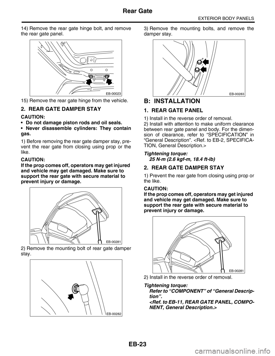
14) Remove the rear gate hinge bolt, and remove
the rear gate panel.
15) Remove the rear gate hinge from the vehicle.
2. REAR GATE DAMPER STAY
CAUTION:
•Do not damage piston rods and oil seals.
•Never disassemble cylinders: They contain
gas.
1) Before removing the rear gate damper stay, pre-
vent the rear gate from closing using prop or the
like.
CAUTION:
If the prop comes off, operators may get injured
and vehicle may get damaged. Make sure to
support the rear gate with secure material to
prevent injury or damage.
2) Remove the mounting bolt of rear gate damper
stay.
3) Remove the mounting bolts, and remove the
damper stay.
B: INSTALLATION
1. REAR GATE PANEL
1) Install in the reverse order of removal.
2) Install with attention to make uniform clearance
between rear gate panel and body. For the dimen-
sion of clearance, refer to “SPECIFICATION” in
“General Description”.
TION, General Description.>
Tightening torque:
25 N·m (2.6 kgf-m, 18.4 ft-lb)
2. REAR GATE DAMPER STAY
1) Prevent the rear gate from closing using prop or
the like.
CAUTION:
If the prop comes off, operators may get injured
and vehicle may get damaged. Make sure to
support the rear gate with secure material to
prevent injury or damage.
2) Install in the reverse order of removal.
Tightening torque:
Refer to “COMPONENT” of “General Descrip-
tion”.
NENT, General Description.>
EB-00023
EB-00281
EB-00282
EB-00283
EB-00281
Page 243 of 2453
EB-24
Rear Gate
EXTERIOR BODY PANELS
C: DISPOSAL
1. REAR GATE DAMPER STAY
CAUTION:
Gas is colorless, odorless, and harmless. How-
ever, gas pressure may spray cutting powder or
oil. Be sure to wear dust-resistant goggles.
1) Cover with a vinyl sack as shown in the figure.
NOTE:
Prevent the vinyl sack from being caught by drill
cutting edge
2) Lift the body side slightly with piston rods fully
extended, and secure the body side with vise.
Drill a hole in 2 to 3 mm (0.08 to 0.12 in) diameter at
a point 10 to 200 mm (0.39 to 7.87 in) from door
side, and bleed rear gate damper stay gas stay
completely.
(1) Rear gate damper stay
(2) Vinyl sack
(1) Body side
(2) Door side
(3) 190 mm (7.48 in)
(4) 10 mm (0.39 in)
(5) Piston rod
(6) Cylinder
(7) Portion to be drilled
(1)
(2)
EB-00031
(3) (4)
(1)
(5)(6)
(7)
(2)
EB-00032
Page 264 of 2453
EI-22
Front Bumper
EXTERIOR/INTERIOR TRIM
2. FRONT BUMPER BEAM ASSEMBLY
1) Remove the front bumper face.
2) Remove the energy absorber foam from bumper
beam.
3) Remove the bolts, and remove the bumper
beam assembly from vehicle body.
NOTE:
After all bolts are removed, raise the whole bumper
beam a little to remove it from vehicle body.
B: INSTALLATION
1. FRONT BUMPER FACE
1) Mount the bumper face securely in the gap be-
tween guide bracket (A) and fender (B).
2) Install in the reverse order of removal.
2. FRONT BUMPER BEAM ASSEMBLY
Install in the reverse order of removal.
Tightening torque:
Refer to “COMPONENT” of “General Descrip-
tion”.
NENT, General Description.>
EI-01271
EI-01272
(A)
(B)