2009 SUBARU TRIBECA ECU
[x] Cancel search: ECUPage 361 of 2453

AC-35
Heater and Cooling Unit
HVAC SYSTEM (HEATER, VENTILATOR AND A/C)
16.Heater and Cooling Unit
A: REMOVAL
1. FRONT
1) Disconnect the ground cable from battery.
2) Using the refrigerant recovery system, dis-
charge refrigerant.
3) Drain engine coolant from the radiator.
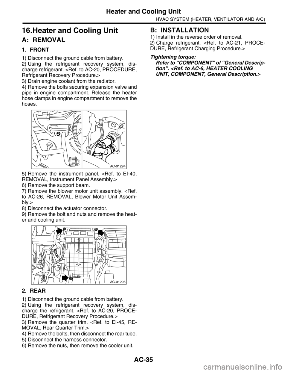
4) Remove the bolts securing expansion valve and
pipe in engine compartment. Release the heater
hose clamps in engine compartment to remove the
hoses.
5) Remove the instrument panel.
6) Remove the support beam.
7) Remove the blower motor unit assembly.
bly.>
8) Disconnect the actuator connector.
9) Remove the bolt and nuts and remove the heat-
er and cooling unit.
2. REAR
1) Disconnect the ground cable from battery.
2) Using the refrigerant recovery system, dis-
charge the refrigerant.
3) Remove the quarter trim.
4) Remove the bolts, then disconnect the rear tube.
5) Disconnect the harness connector.
6) Remove the nuts, then remove the cooler unit.
B: INSTALLATION
1) Install in the reverse order of removal.
2) Charge refrigerant.
Tightening torque:
Refer to “COMPONENT” of “General Descrip-
tion”.
AC-01294
AC-01295
Page 418 of 2453

IM (diag)-2
Basic Diagnostic Procedure
IMMOBILIZER (DIAGNOSTICS)
1. Basic Diagnostic Procedure
A: PROCEDURE
Step Check Yes No
1CHECK SECURITY INDICATOR LIGHT.
1) Turn the ignition switch to “OFF” or “ACC”.
2) Wait for 60 seconds or more.
Does the security indicator
light blink?
Go to step 2.Check the secu-
rity indicator light
circuit.
SECURITY INDI-
CATOR LIGHT
CIRCUIT,
INSPECTION,
Diagnostics Chart
for Secur ity Indica-
tor Light.>
2CHECK KEY SWITCH.
Remove the key from ignition switch.
Does the security indicator
light blink within 1 second after
removing the key?
Go to step 3.Check the key
switch circuit.
SWITCH CIR-
CUIT, INSPEC-
TION, Diagnostics
Chart for Security
Indicator Light.>
3CHECK SECURITY INDICATOR LIGHT.
Tu r n t h e i g n i t i o n s w i t c h t o O N .
Does the security indicator
light go off?
Go to step 5.Go to step 4.
4CHECK ENGINE START.
Tu r n t h e i g n i t i o n s w i t c h t o S TA R T.
Does the starter operate? Check the LAN
communication cir-
cuit.
Diagnostic Proce-
dure.>
Check the DTC
display (body inte-
grated unit). Go to
step 7.
5CHECK ENGINE START.
Tu r n t h e i g n i t i o n s w i t c h t o S TA R T.
Does the starter operate? Go to step 6.Check the LAN
communication cir-
cuit.
Diagnostic Proce-
dure.>
6CHECK ENGINE START.
Tu r n t h e i g n i t i o n s w i t c h t o S TA R T.
Does the engine start? Immobilizer sys-
tem is OK.
Check the DTC
display (ECM). Go
to step 7.
7CHECK ANY OTHER DTC ON DISPLAY.
1) Turn the ignition switch to OFF.
2) Connect the Subaru Select Monitor to data
link connector.
3) Turn the ignition switch and Subaru Select
Monitor switch to ON.
4) Read DTC on display.
Is the DTC displayed on
screen?
Go to step 8.Repair the related
parts.
8PERFORM THE DIAGNOSIS.
1) Inspect using the “Diagnostic Procedure
with Diagnostic Trouble Code (DTC).”
nostic Trouble Code (DTC).>
2) Repair the trouble cause.
3) Perform the clear memory mode.
4) Read DTC again.
Is the DTC displayed on
screen?
Inspect using the
“Diagnostic Proce-
dure with Diagnos-
tic Trouble Code
(DTC).”
nostic Procedure
with Diagnostic
Tr o u b l e C o d e
(DTC).>
Finish the diagno-
sis.
Page 419 of 2453

IM (diag)-3
General Description
IMMOBILIZER (DIAGNOSTICS)
2. General Description
A: CAUTION
CAUTION:
•The airbag system wiring harnesses and con-
nectors are yellow. Do not use electrical test
equipment on these circuits.
•Be careful not to damage the airbag system
wiring harness.
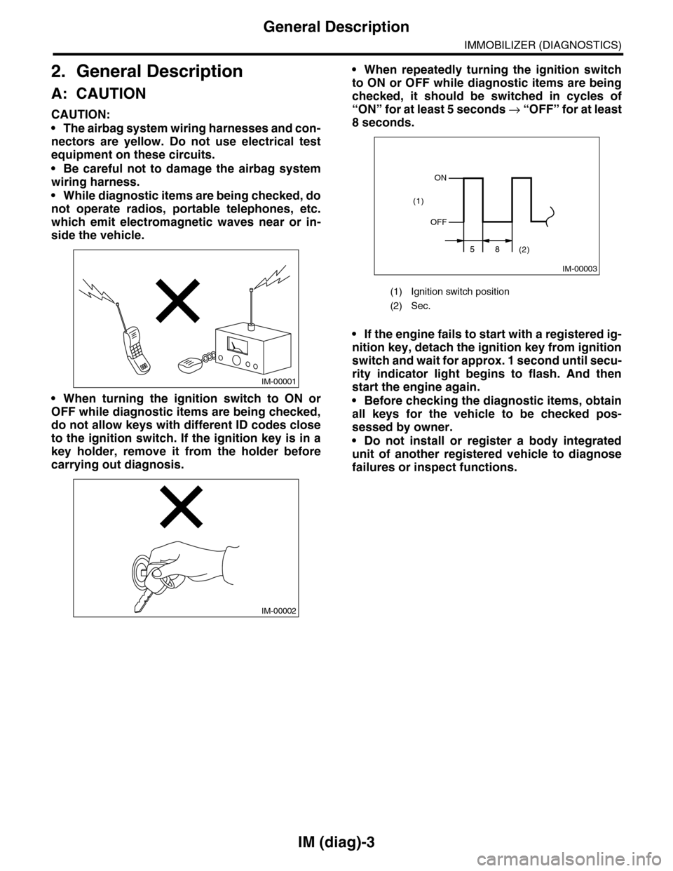
•While diagnostic items are being checked, do
not operate radios, portable telephones, etc.
which emit electromagnetic waves near or in-
side the vehicle.
•When turning the ignition switch to ON or
OFF while diagnostic items are being checked,
do not allow keys with different ID codes close
to the ignition switch. If the ignition key is in a
key holder, remove it from the holder before
carrying out diagnosis.
•When repeatedly turning the ignition switch
to ON or OFF while diagnostic items are being
checked, it should be switched in cycles of
“ON” for at least 5 seconds → “O F F ” fo r a t le a s t
8 seconds.
•If the engine fails to start with a registered ig-
nition key, detach the ignition key from ignition
switch and wait for approx. 1 second until secu-
rity indicator light begins to flash. And then
start the engine again.
•Before checking the diagnostic items, obtain
all keys for the vehicle to be checked pos-
sessed by owner.
•Do not install or register a body integrated
unit of another registered vehicle to diagnose
failures or inspect functions.
IM-00001
IM-00002
(1) Ignition switch position
(2) Sec.
IM-00003
ON
OFF
58(2)
(1)
Page 421 of 2453

IM (diag)-5
Electrical Component Location
IMMOBILIZER (DIAGNOSTICS)
3. Electrical Component Location
A: LOCATION
(1) Antenna (3) Body integrated unit (4) Transponder
(2) Security indicator light (LED bulb)
IM-00140
SECURITY(1)(2)
(4)
(3)
Page 423 of 2453

IM (diag)-7
Subaru Select Monitor
IMMOBILIZER (DIAGNOSTICS)
5. Subaru Select Monitor
A: OPERATION
1. HOW TO USE SUBARU SELECT MONI-
TOR
1) Prepare the Subaru Select Monitor kit.
2) Connect the diagnosis cable to Subaru Select
Monitor.
3) Insert the cartridge to Subaru Select Monitor.
4) Connect the Subaru Select Monitor to data link
connector.
(1) Data link connector is located in the lower
portion of the instrument panel (on the driver’s
side).
(2) Connect the diagnosis cable to data link
connector.
CAUTION:
Do not connect the scan tools except for Suba-
ru Select Monitor.
5) Turn the ignition switch to ON (engine OFF), and
the Subaru Select Monitor switch to ON.
6) Using the Subaru Select Monitor, call up DTC
and various data, then record them.
2. READ DIAGNOSTIC TROUBLE CODE
(DTC) FOR ENGINE AND BODY INTEGRAT-
ED UNIT
Refer to “Read Diagnostic Trouble Code” for infor-
mation about how to indicate DTC.
3. COMMUNICATION LINE CHECK
NOTE:
The communication line between ECM and body
integrated unit can be checked in “System Opera-
tion Check Mode”. This is referred to as “Commu-
nication line check”.
1) Connect the Subaru Select Monitor.
2) On the «Main Menu» display screen, select the
{Each System Check} and press the [YES] key.
3) On the «System Selection Menu» display screen,
select the {Engine} and press the [YES] key.
4) Press the [YES] key after the information of en-
gine type is displayed.
5) On the «Engine Diagnosis» display screen, se-
lect the {System Operation Check Mode} and press
the [YES] key.
6) On the «System operation check mode» display,
select the {security system}.
7) Start the communication line check.
8) Is «OK» displayed on screen?
If displayed, go to step 9).
If «NO», go to step 10).
9) After diagnostic results, it is determined that the
circuit is not shorted. Finish the communication line
check.
10) If a problem is detected, repair the trouble
cause.
Diagnostic Procedure with Diagnostic Trouble
Code (DTC).>
CC-00028
CC-00029
LAN00189
(1) Power switch
LAN00017
(A)
Page 426 of 2453

IM (diag)-10
Diagnostics Chart for Security Indicator Light
IMMOBILIZER (DIAGNOSTICS)
8. Diagnostics Chart for Security Indicator Light
A: INSPECTION
1. CHECK SECURITY INDICATOR LIGHT CIRCUIT
WIRING DIAGRAM:
IM-00141
MAIN SBF
SBF-3
BATTERY
WARNING BOX
BODY INTEGRATED UNIT
i116
F/B NO.7
F/B NO.12
IGNITIONSWITCH
A33C2B7C9C8
2
1
E
A1
M/B NO.8
SBF-8
B22
i84A:
B280B:
B281C:
567821943102422 23 25111213141526 27281617181920 21
B281i84
1234567891011121314151617181920212223242526272829303132333435
5467821931022 231112131415242526 2716171828 29192021 30
B280A:C:B:
5i124
i102
i97
i98
SECURITYINDICATORLIGHT
JOINT CONNECTOR
i116
12345678910i98
i97
12345678910111213141516171819202122
: TERMINAL NO. OPTIONAL ARRANGEMENT AMONG 16, 17 AND 18
1*
1*
1*
Step Check Yes No
1CHECK SECURITY INDICATOR LIGHT.
1) Turn the ignition switch to OFF.
2) Disconnect the harness connector from
body integrated unit.
3) Connect the resistor (100 Ω) between body
integrated unit harness connector terminal
(i84) No. 33 and chassis ground.
Does the security indicator
light illuminate?
Go to step 2.Go to step 5.
Page 427 of 2453

IM (diag)-11
Diagnostics Chart for Security Indicator Light
IMMOBILIZER (DIAGNOSTICS)
2CHECK BODY INTEGRATED UNIT GROUND
CIRCUIT.
Measure the resistance between body inte-
grated unit harness connector terminal and
chassis ground.
Connector & terminal
(B280) No. 22 — Chassis ground:
(B281) No. 8, No. 9 — Chassis ground:
Is the resistance less than 10
Ω?
Go to step 3.Repair the open
circuit of body inte-
grated unit ground
circuit.
3CHECK BODY INTEGRATED UNIT IGNITION
CIRCUIT.
1) Turn the ignition switch to ON.(Engine OFF)
2) Measure the voltage between body inte-
grated unit harness connector terminal and
chassis ground.
Connector & terminal
(i84) No. 1 (+) — Chassis ground (–):
Is the voltage more than 10 V? Go to step 4.Check the harness
for open or shor t
circuit between
body integrated
unit and ignition
switch.
4CHECK BODY INTEGRATED UNIT POWER
SUPPLY CIRCUIT.
1) Turn the ignition switch to OFF.
2) Measure the voltage between body inte-
grated unit harness connector terminal and
chassis ground.
Connector & terminal
(B280) No. 7 (+) — Chassis ground (–):
(B281) No. 2 (+) — Chassis ground (–):
Is the voltage more than 10 V? Replace the body
integrated unit
Unit.> and replace
all the ignition keys
(including tran-
sponder). Execute
the registration
procedure next.
Refer to the “REG-
ISTRATION MAN-
UAL FO R
IMMOBILIZER”.
Check the harness
for open or shor t
circuit between
body integrated
unit and fuse.
5INSPECT WARNING BOX CIRCUIT.
1) Remove the warning box.
2) Measure the voltage between the warning
box harness connector terminal and chassis
ground.
Connector & terminal
(i116) No. 1 (+) — Chassis ground (–):
Is the voltage more than 10 V? Go to step 6.Check the harness
for open or shor t
circuit between
warning box and
fuse.
6INSPECT WARNING BOX CIRCUIT.
Measure the resistance between body inte-
grated unit harness connector terminal and
warning box harness connector terminal.
Connector & terminal
(i84) No. 33 — (i116) No. 2:
Is the resistance less than 10
Ω?
LED bulb malfunc-
tion. Replace the
warning box.
REMOVAL, Warn-
ing Box.>
Repair the har-
ness or connector.
Step Check Yes No
Page 428 of 2453

IM (diag)-12
Diagnostics Chart for Security Indicator Light
IMMOBILIZER (DIAGNOSTICS)
2. CHECK KEY SWITCH CIRCUIT
WIRING DIAGRAM:
IM-00078
B350
KEY WARNINGSWITCH
B281
BODY INTEGRATEDMODULE
BATTERYM/B No.14
C7
3
4
C:
567821943102422 23 25111213141526 27281617181920 21
B281C:B350
1234