2009 SUBARU TRIBECA ECU
[x] Cancel search: ECUPage 429 of 2453

IM (diag)-13
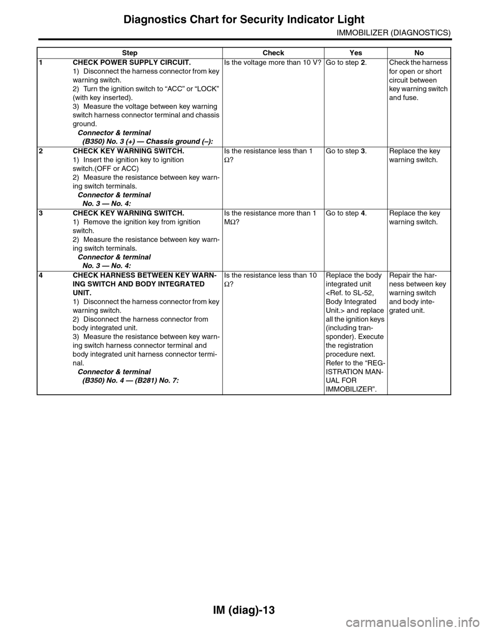
Diagnostics Chart for Security Indicator Light
IMMOBILIZER (DIAGNOSTICS)
Step Check Yes No
1CHECK POWER SUPPLY CIRCUIT.
1) Disconnect the harness connector from key
warning switch.
2) Turn the ignition switch to “ACC” or “LOCK”
(with key inserted).
3) Measure the voltage between key warning
switch harness connector terminal and chassis
ground.
Connector & terminal
(B350) No. 3 (+) — Chassis ground (–):
Is the voltage more than 10 V? Go to step 2.Check the harness
for open or shor t
circuit between
key warning switch
and fuse.
2 CHECK KEY WARNING SWITCH.
1) Insert the ignition key to ignition
switch.(OFF or ACC)
2) Measure the resistance between key warn-
ing switch terminals.
Connector & terminal
No. 3 — No. 4:
Is the resistance less than 1
Ω?
Go to step 3.Replace the key
warning switch.
3 CHECK KEY WARNING SWITCH.
1) Remove the ignition key from ignition
switch.
2) Measure the resistance between key warn-
ing switch terminals.
Connector & terminal
No. 3 — No. 4:
Is the resistance more than 1
MΩ?
Go to step 4.Replace the key
warning switch.
4CHECK HARNESS BETWEEN KEY WARN-
ING SWITCH AND BODY INTEGRATED
UNIT.
1) Disconnect the harness connector from key
warning switch.
2) Disconnect the harness connector from
body integrated unit.
3) Measure the resistance between key warn-
ing switch harness connector terminal and
body integrated unit harness connector termi-
nal.
Connector & terminal
(B350) No. 4 — (B281) No. 7:
Is the resistance less than 10
Ω?
Replace the body
integrated unit
Unit.> and replace
all the ignition keys
(including tran-
sponder). Execute
the registration
procedure next.
Refer to the “REG-
ISTRATION MAN-
UAL FO R
IMMOBILIZER”.
Repair the har-
ness between key
warning switch
and body inte-
grated unit.
Page 432 of 2453

IM (diag)-16
Diagnostic Procedure with Diagnostic Trouble Code (DTC)
IMMOBILIZER (DIAGNOSTICS)
10.Diagnostic Procedure with Diagnostic Trouble Code (DTC)
A: DTC P0513 INCORRECT IMMOBILIZER KEY
DTC DETECTING CONDITION:
Incorrect immobilizer key (Use of unregistered key in body integrated unit)
Step Check Yes No
1PERFORM TEACHING OPERATION OF IG-
NITION KEY.
Perfor m teaching operation on all keys of the
vehicle. Refer to the “REGISTRATION MAN-
UAL FOR IMMO BILIZER”.
Is the teaching operation for all
keys completed?
END. Replace the igni-
tion keys (includ-
ing transponder)
which cannot be
registered. Go to
step 2.
2PERFORM TEACHING OPERATION OF IG-
NITION KEY.
Perfor m teaching operation on all keys of the
vehicle. Refer to the “REGISTRATION MAN-
UAL FOR IMMO BILIZER”.
Is the teaching operation for all
keys completed?
END. Replace the body
integrated unit
Unit.> and replace
all the ignition keys
(including tran-
sponder). Execute
the registration
procedure next.
Refer to the “REG-
ISTRATION MAN-
UAL FOR
IMMOBILIZER”.
Page 434 of 2453

IM (diag)-18
Diagnostic Procedure with Diagnostic Trouble Code (DTC)
IMMOBILIZER (DIAGNOSTICS)
Step Check Yes No
1CHECK ANTENNA CIRCUIT.
1) Turn the ignition switch to OFF.
2) Disconnect the harness connector from
antenna.
3) Measure the resistance of antenna circuit.
Connector & terminal
(B351) No. 1 — No. 2:
Is the resistance less than 10
Ω?
Go to step 2.Replace the
antenna.
lizer Antenna.>
2CHECK ANTENNA CIRCUIT.
1) Disconnect the harness connector from
body integrated unit.
2) Measure the resistance between harness
connector and chassis ground.
Connector & terminal
(B281) No. 21 — Chassis ground:
Is the resistance less than 10
Ω?
Repair the har-
ness.
Go to step 3.
3CHECK ANTENNA CIRCUIT.
Measure the resistance between harness con-
nector and chassis ground.
Connector & terminal
(B281) No. 20 — Chassis ground:
Is the resistance less than 10
Ω?
Repair the har-
ness.
Go to step 4.
4CHECK ANTENNA CIRCUIT.
1) Turn the ignition switch to ON.(Engine OFF)
2) Measure the voltage between harness con-
nector and chassis ground.
Connector & terminal
(B281) No. 21 (+) — Chassis ground (–):
Is the voltage 0 V? Go to step 5.Repair the har-
ness.
5CHECK ANTENNA CIRCUIT.
Measure the voltage between harness connec-
tor and chassis ground.
Connector & terminal
(B281) No. 20 (+) — Chassis ground (–):
Is the voltage 0 V? Go to step 6.Repair the har-
ness between
body integrated
unit and antenna,
because there is
short circuit with
battery voltage line
or ignition switch
“ON” line.
6CHECK BODY INTEGRATED UNIT FUNC-
TION.
1) Turn the ignition switch to OFF.
2) Connect the harness connector to body
integrated unit.
3) Insert the key to ignition switch, and mea-
sure the changes in voltage between antenna
harness connectors.
Connector & terminal
(B281) No. 20 (+) — No. 21 (–):
Is the voltage –30 to 30 V?
(Approx. 0.1 second after
inserting the key) Is the voltage
0 V? (Approx. 1 second after
inserting the key)
Go to step 7.Replace the body
integrated unit
Unit.> and replace
all the ignition keys
(including tran-
sponder). Execute
the registration
procedure next.
Refer to the “REG-
ISTRATION MAN-
UAL FOR
IMMOBILIZER”.
Page 435 of 2453

IM (diag)-19
Diagnostic Procedure with Diagnostic Trouble Code (DTC)
IMMOBILIZER (DIAGNOSTICS)
C: DTC P1571 REFERENCE CODE INCOMPATIBILITY
DTC DETECTING CONDITION:
Reference code incompatibility between body integrated unit and ECM
7CHECK IGNITION KEY (TRANSPONDER).
1) Remove the key from ignition switch.
2) Start the engine using other key which is
already registered.
Does the engine start? Replace all the
ignition keys
(including tran-
sponder). Execute
the registration
procedure next.
Refer to the “REG-
ISTRATION MAN-
UAL FO R
IMMOBILIZER”.
Replace the body
integrated unit
Unit.> and replace
all the ignition keys
(including tran-
sponder). Execute
the registration
procedure next.
Refer to the “REG-
ISTRATION MAN-
UAL FOR
IMMOBILIZER”.
Step Check Yes No
Step Check Yes No
1PERFORM TEACHING OPERATION OF IG-
NITION KEY.
Perfor m teaching operation on all keys of the
vehicle. Refer to the “REGISTRATION MAN-
UAL FOR IMMO BILIZER”.
Is the teaching operation for all
keys completed?
END. Go to step 2.
2CHECK ANY OTHER DTC ON DISPLAY.Is any other immobilizer DTC
displayed?
Check the appro-
priate DTC using
the “List of Diag-
nostic Trouble
Code (DTC)”.
nostic Trouble
Code (DTC).>
Execute the regis-
tration procedure
next. Refer to the
“REGISTRATION
MANUAL FOR
IMMOBILIZER”.
Replace the ECM.
Engine Control
Module
(ECM).>Replace
the body inte-
grated unit
Integrated Unit.>
and replace all the
ignition keys
(including tran-
sponder). Execute
the registration
procedure next.
Refer to the “REG-
ISTRATION MAN-
UAL FOR
IMMOBILIZER”.
Page 437 of 2453

IM (diag)-21
Diagnostic Procedure with Diagnostic Trouble Code (DTC)
IMMOBILIZER (DIAGNOSTICS)
3CHECK BODY INTEGRATED UNIT GROUND
CIRCUIT.
1) Turn the ignition switch to OFF.
2) Measure the resistance between body inte-
grated unit harness connector terminal and
chassis ground.
Connector & terminal
(B280) No. 22 — Chassis ground:
(B281) No. 8, No. 9 — Chassis ground:
Is the resistance less than 10
Ω?
Go to step 4.Repair the open
circuit of body inte-
grated unit ground
circuit.
4CHECK HARNESS BETWEEN BODY INTE-
GRATED UNIT AND ECM.
1) Disconnect the harness connector from
body integrated unit and ECM.
2) Measure the resistance between body inte-
grated unit harness connector terminal and
ECM harness connector terminal.
Connector & terminal
(B280) No. 18 — (B136) No. 26:
Is the resistance less than 10
Ω?
Go to step 5.Repair the open
circuit of harness
between body inte-
grated unit and
ECM.
5CHECK HARNESS BETWEEN BODY INTE-
GRATED UNIT AND ECM.
Measure the resistance between body inte-
grated unit harness connector terminal and
ECM harness connector terminal.
Connector & terminal
(B280) No. 28 — (B136) No. 34:
Is the resistance less than 10
Ω?
Go to step 6.Repair the open
circuit of harness
between body inte-
grated unit and
ECM.
6CHECK HARNESS OF COMMUNICATION
LINE.
1) Turn the ignition switch to ON.(Engine OFF)
2) Measure the voltage between body inte-
grated unit harness connector terminal and
chassis ground.
Connector & terminal
(B280) No. 18, No. 28 (+) — Chassis
ground (–):
Is the voltage 0 V? Go to step 7.Repair the har-
ness between
body integrated
unit and ECM,
because there is
short circuit with
battery voltage line
or ignition switch
“ON” line.
7CHECK HARNESS OF COMMUNICATION
LINE.
Measure the voltage between harness connec-
tor terminal and engine ground.
Connector & terminal
(B136) No. 26, No. 34 (+) — Engine
ground (–):
Is the voltage 0 V? Go to step 8.Repair the har-
ness between
body integrated
unit and ECM,
because there is
short circuit with
battery voltage line
or ignition switch
“ON” line.
8CHECK ECM BY COMMUNICATION LINE
CHECK.
1) Connect the harness connector to ECM.
2) Disconnect the harness connector from
body integrated unit.
3) Start the communication line check.
CHECK, OPERATION, Subaru Select Moni-
tor.>
Does “Communication Line not
Shorted” appear on the
screen?
Replace the body
integrated unit
Unit.> and replace
all the ignition keys
(including tran-
sponder). Execute
the registration
procedure next.
Refer to the “REG-
ISTRATION MAN-
UAL FO R
IMMOBILIZER”.
Replace the ECM.
Engine Control
Module (ECM).>
Per fo r m th e re g is -
tration procedure
next. Refer to the
“REGISTRATION
MANUAL FOR
IMMOBILIZER”.
Step Check Yes No
Page 438 of 2453

IM (diag)-22
Diagnostic Procedure with Diagnostic Trouble Code (DTC)
IMMOBILIZER (DIAGNOSTICS)
E: DTC P1574 KEY COMMUNICATION FAILURE
DTC DETECTING CONDITION:
Failure of body integrated unit to verify key (transponder) ID code
Step Check Yes No
1CHECK BODY INTEGRATED UNIT FUNC-
TION.
Insert the key to ignition switch (LOCK posi-
tion), and measure the changes in voltage
between antenna connectors.
Connector & terminal
(B142) No. 1 (+) — No. 2 (–):
Is the voltage –30 to 30 V?
(Approx. 0.1 second after
inserting the key) Is the voltage
0 V? (Approx. 1 second after
inserting the key)
Go to step 2.Replace the body
integrated unit
Unit.> and replace
all the ignition keys
(including tran-
sponder). Execute
the registration
procedure next.
Refer to the “REG-
ISTRATION MAN-
UAL FOR
IMMOBILIZER”.
2CHECK IGNITION KEY (TRANSPONDER).
1) Remove the key from ignition switch.
2) Start the engine using other key which is
already registered.
Does the engine start? Replace all the
ignition keys
(including tran-
sponder). Execute
the registration
procedure next.
Refer to the “REG-
ISTRATION MAN-
UAL FO R
IMMOBILIZER”.
Replace the body
integrated unit
Unit.> and replace
all the ignition keys
(including tran-
sponder). Execute
the registration
procedure next.
Refer to the “REG-
ISTRATION MAN-
UAL FOR
IMMOBILIZER”.
Page 440 of 2453

IM (diag)-24
Diagnostic Procedure with Diagnostic Trouble Code (DTC)
IMMOBILIZER (DIAGNOSTICS)
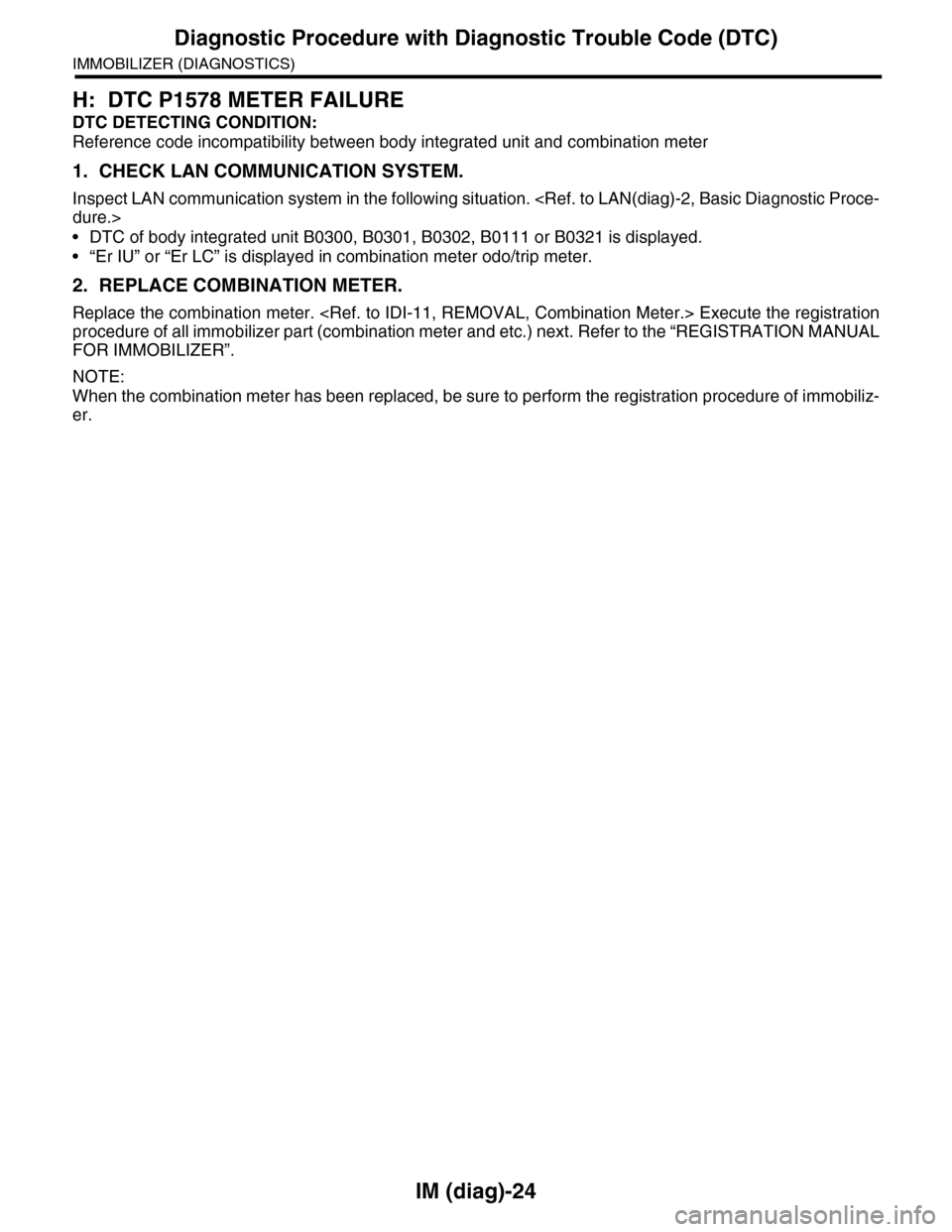
H: DTC P1578 METER FAILURE
DTC DETECTING CONDITION:
Reference code incompatibility between body integrated unit and combination meter
1. CHECK LAN COMMUNICATION SYSTEM.
Inspect LAN communication system in the following situation.
•DTC of body integrated unit B0300, B0301, B0302, B0111 or B0321 is displayed.
•“Er IU” or “Er LC” is displayed in combination meter odo/trip meter.
2. REPLACE COMBINATION METER.
Replace the combination meter.
procedure of all immobilizer part (combination meter and etc.) next. Refer to the “REGISTRATION MANUAL
FOR IMMOBILIZER”.
NOTE:
When the combination meter has been replaced, be sure to perform the registration procedure of immobiliz-
er.
Page 441 of 2453

IDI-2
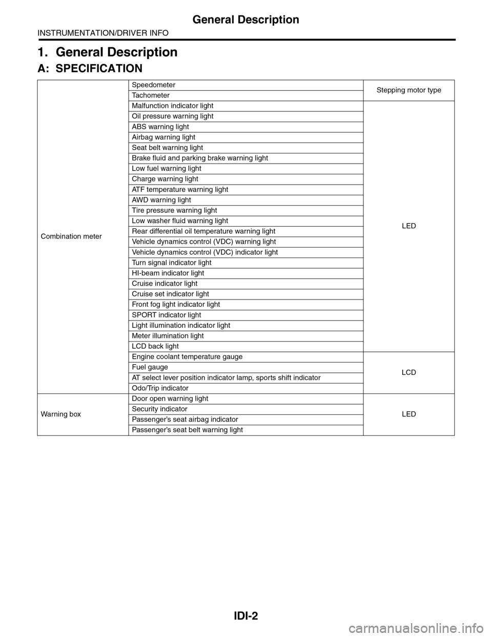
General Description
INSTRUMENTATION/DRIVER INFO
1. General Description
A: SPECIFICATION
Combination meter
SpeedometerStepping motor typeTa c h o m e t e r
Malfunction indicator light
LED
Oil pressure warning light
ABS warning light
Airbag warning light
Seat belt warning light
Brake fluid and parking brake warning light
Low fuel warning light
Charge warning light
AT F t e m p e r a t u r e w a r n i n g l i g h t
AW D war n in g l i gh t
Tire pressure warning light
Low washer fluid warning light
Rear differential oil temperature warning light
Ve h i c l e d y n a m i c s c o n t r o l ( V D C ) w a r n i n g l i g h t
Ve h i c l e d y n a m i c s c o n t r o l ( V D C ) i n d i c a t o r l i g h t
Tu r n s i g n a l i n d i c a t o r l i g h t
HI-beam indicator light
Cruise indicator light
Cruise set indicator light
Fr o nt fog li g ht i nd i ca to r li g ht
SPORT indicator light
Light illumination indicator light
Meter illumination light
LCD back light
Engine coolant temperature gauge
LCDFuel gauge
AT s e l e c t l e v e r p o s i t i o n i n d i c a t o r l a m p , s p o r t s s h i f t i n d i c a t o r
Odo/Trip indicator
Wa r ni n g b ox
Door open warning light
LEDSecurity indicator
Passenger’s seat airbag indicator
Passenger’s seat belt war ning light