Page 289 of 2453

EI-47
Floor Mat
EXTERIOR/INTERIOR TRIM
20.Floor Mat
A: REMOVAL
1. FRONT FLOOR MAT
1) Remove the front seats.
AL, Front Seat.>
2) Remove the second–row seats.
REMOVAL, Second-row Seats.>
3) Remove the console box.
MOVAL, Console Box.>
4) Remove the instrument panel lower cover.
to EI-36, REMOVAL, Instrument Panel Lower Cov-
er.>
5) Remove the glove box.
AL, Glove Box.>
6) Remove the following trims.
MOVAL, Side Trim.>
•Front door scuff plate
•Rear door scuff plate
•Front pillar lower trim
•Center pillar lower trim
7) Remove the remote opener cover.
45, REMOVAL, Remote Openers.>
8) Remove the navigation unit.
MOVAL, Navigation Body.>
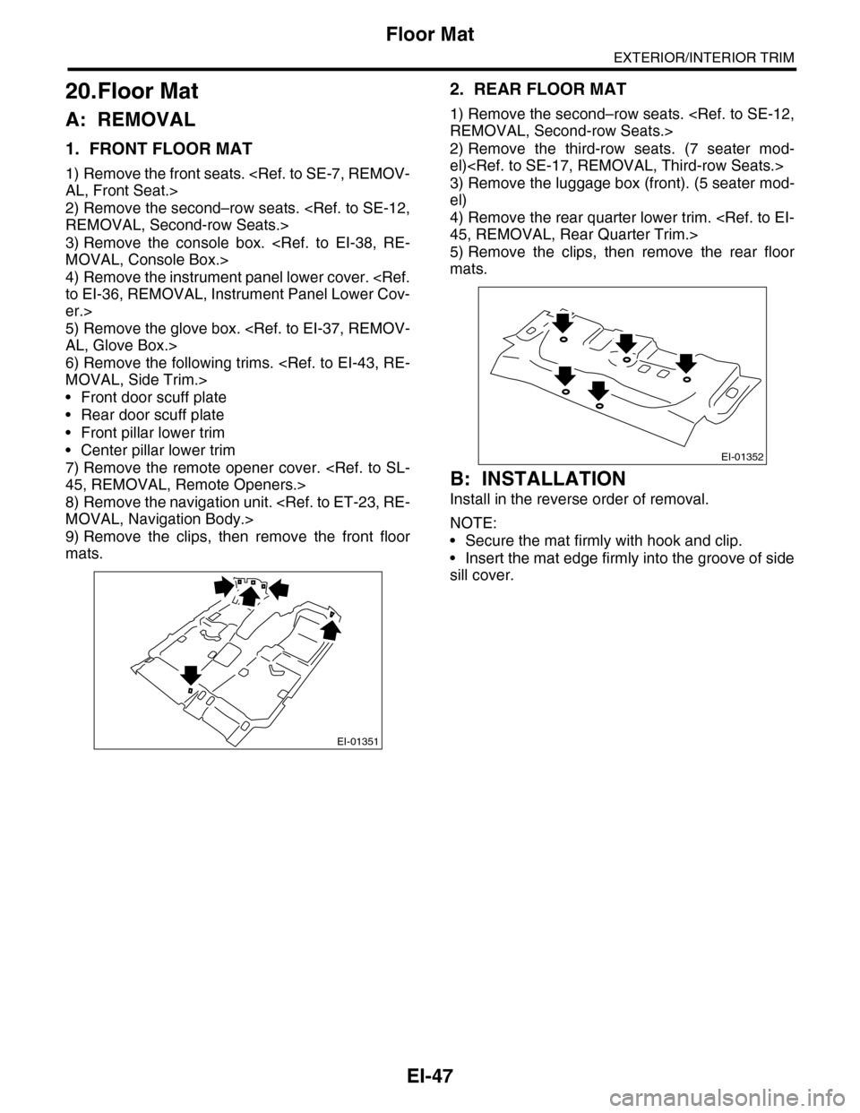
9) Remove the clips, then remove the front floor
mats.
2. REAR FLOOR MAT
1) Remove the second–row seats.
REMOVAL, Second-row Seats.>
2) Remove the third-row seats. (7 seater mod-
el)
3) Remove the luggage box (front). (5 seater mod-
el)
4) Remove the rear quarter lower trim.
45, REMOVAL, Rear Quarter Trim.>
5) Remove the clips, then remove the rear floor
mats.
B: INSTALLATION
Install in the reverse order of removal.
NOTE:
•Secure the mat firmly with hook and clip.
•Insert the mat edge firmly into the groove of side
sill cover.
EI-01351
EI-01352
Page 304 of 2453
GW-9
Front Door Glass
GLASS/WINDOWS/MIRRORS
4. Front Door Glass
A: REMOVAL
1) Remove the front door trim.
MOVAL, Door Trim.>
2) Remove the sealing cover.
MOVAL, Front Sealing Cover.>
3) Operate the power window switch to move the
glass to the position shown in the figure, and then
remove the two bolts through service holes.
4) Tilt the door glass forward, then remove the door
glass from the glass run rubber.
5) Remove the door glass.
CAUTION:
•Since the gear may be disengaged, do not
turn regulator in the closing direction after re-
moving glass.
•Avoid impact and damage to the glass.
6) Remove the bolt (A), and then remove the door
sash (B).
B: INSTALLATION
Install in the reverse order of removal.
CAUTION:
Make sure that the glass stay is placed securely
in sash.
Tightening torque:
Refer to “COMPONENT” of “General Descrip-
tion”.
COMPONENT, General Description.>
GW-00479
GW-00480
Page 305 of 2453
GW-10
Front Regulator and Motor Assembly
GLASS/WINDOWS/MIRRORS
5. Front Regulator and Motor
Assembly
A: REMOVAL
1) Remove the door glass.
MOVAL, Front Door Glass.>
2) Disconnect the motor connector.
3) Remove the four bolts and two nuts to remove
regulator assembly.
4) Remove the screws to remove motor assembly.
NOTE:
When removing the motor assembly, secure the
arm correctly. Otherwise the regulator arm moves
with the force of balancing spring.
B: INSTALLATION
Install in the reverse order of removal.
Tightening torque:
Refer to “COMPONENT” of “General Descrip-
tion”.
COMPONENT, General Description.>
C: INSPECTION
1) Make sure that the power window motor rotates
properly when the battery voltage is applied to the
terminals of motor connector.
2) Change polarity of battery connection to termi-
nals to ensure that the motor rotates in reverse di-
rection.
GW-00481
GW-00482
Page 307 of 2453
GW-12
Scalp Cap
GLASS/WINDOWS/MIRRORS
7. Scalp Cap
A: REPLACEMENT
1) Remove the outer mirror.
PLACEMENT, Outer Mirror.>
2) Press in the upper side clips (A) from inside of
the outer mirror.
3) Pull the scalp cap frontward of outer mirror, re-
move the upper side clips (A) and lower side hooks
(B), and then remove the scalp cap.
4) Insert the lower hooks (B) of scalp cap to outer
mirror and push the upper clips (A) in.
5) Install the scalp cap securely.
CAUTION:
Do not remove the scalp cap forcibly. The lower
hooks may be damaged.
GW-00312
(A)(A)
(A)
GW-00275(B)
(B)
(A)
GW-00276
Page 309 of 2453
GW-14
Outer Mirror
GLASS/WINDOWS/MIRRORS
9. Outer Mirror
A: REPLACEMENT
1) Face the mirror upward.
2) Use a flat tip screwdriver to remove clip (A).
3) Lift the lower mirror up to remove hooks (B).
4) Disconnect the mirror heater connector from
side of the mirror. (Model with mirror heater)
5) Catch the hooks (B) and install clips (A).
CAUTION:
•When removing the mirror, be careful not to
damage the back surface of mirror with a flat tip
screwdriver.
•When installing the mirror, insert the hook
and clip securely.
(A)
GW-00279
(B)
GW-00280
(B)
GW-00450(A)
Page 311 of 2453

GW-16
Rear Door Glass
GLASS/WINDOWS/MIRRORS
11.Rear Door Glass
A: REMOVAL
1) Remove the rear door trim.
MOVAL, Door Trim.>
2) Remove the sealing cover.
MOVAL, Rear Sealing Cover.>
3) Apply the protective tape (1) to the areas as
shown in the figure.
4) Operate the power window switch to move the
glass to the position shown in the figure, and then
remove the two bolts through service holes.
5) Remove the sash retaining bolts (A), and loosen
the retaining nuts (B).
6) Move the sash (C) upward, and move the nut (B)
to the position on rear door as shown in the figure.
7) Detach the rear part of door glass from sash (1),
and move it backward (2). Tilt the door glass in-
ward, and move it upward to remove (3).
CAUTION:
•Since the gear may be disengaged, do not
turn regulator in the closing direction after re-
moving glass.
•Avoid impact and damage to the glass.
8) Remove the glass run rubber.
9) Remove the door sash.
B: INSTALLATION
Install in the reverse order of removal.
CAUTION:
Make sure that the glass run rubber is placed
securely in door frame and sash.
Tightening torque:
Refer to “COMPONENT” of “General Descrip-
tion”.
COMPONENT, General Description.>
GW-00487
(1)
GW-00488
GW-00491
(B)
(A)
GW-00489
(C)
(B)
GW-00490
(1)
(2)
(3)
Page 313 of 2453

GW-18
Windshield Glass
GLASS/WINDOWS/MIRRORS
13.Windshield Glass
A: REMOVAL
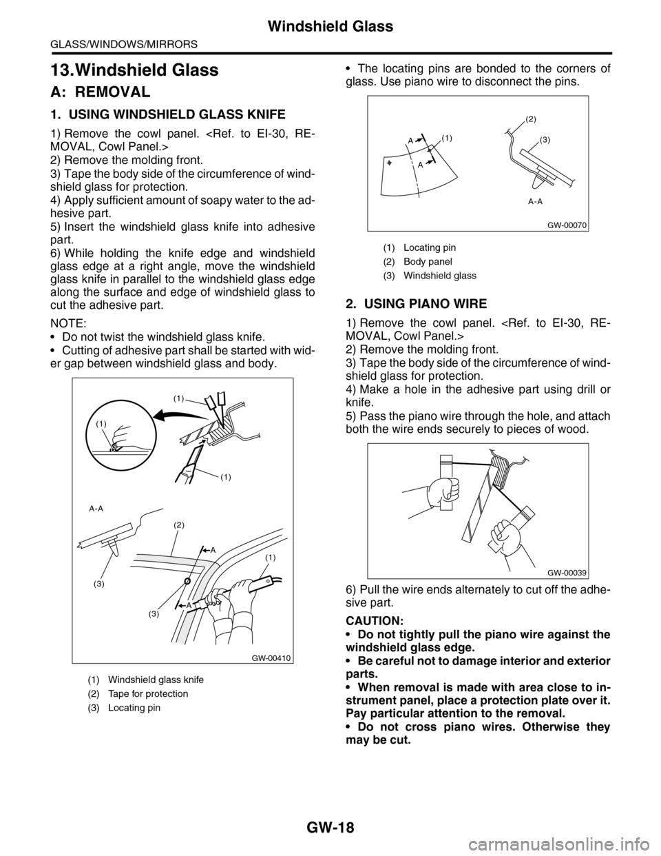
1. USING WINDSHIELD GLASS KNIFE
1) Remove the cowl panel.
MOVAL, Cowl Panel.>
2) Remove the molding front.
3) Tape the body side of the circumference of wind-
shield glass for protection.
4) Apply sufficient amount of soapy water to the ad-
hesive part.
5) Insert the windshield glass knife into adhesive
part.
6) While holding the knife edge and windshield
glass edge at a right angle, move the windshield
glass knife in parallel to the windshield glass edge
along the surface and edge of windshield glass to
cut the adhesive part.
NOTE:
•Do not twist the windshield glass knife.
•Cutting of adhesive part shall be started with wid-
er gap between windshield glass and body.
•The locating pins are bonded to the corners of
glass. Use piano wire to disconnect the pins.
2. USING PIANO WIRE
1) Remove the cowl panel.
MOVAL, Cowl Panel.>
2) Remove the molding front.
3) Tape the body side of the circumference of wind-
shield glass for protection.
4) Make a hole in the adhesive part using drill or
knife.
5) Pass the piano wire through the hole, and attach
both the wire ends securely to pieces of wood.
6) Pull the wire ends alternately to cut off the adhe-
sive part.
CAUTION:
•Do not tightly pull the piano wire against the
windshield glass edge.
•Be careful not to damage interior and exterior
parts.
•When removal is made with area close to in-
strument panel, place a protection plate over it.
Pay particular attention to the removal.
•Do not cross piano wires. Otherwise they
may be cut.
(1) Windshield glass knife
(2) Tape for protection
(3) Locating pin
GW-00410
(1)
(1)
(1)
(3)
(3)
(2)
(1)A
A-A
A
(1) Locating pin
(2) Body panel
(3) Windshield glass
(1)
(2)
(3)
A
A
GW-00070
A-A
GW-00039
Page 317 of 2453
GW-22
Rear Gate Glass
GLASS/WINDOWS/MIRRORS
15.Rear Gate Glass
A: REMOVAL
1) Remove the rear wiper motor.
REMOVAL, Rear Wiper Motor.>
2) Disconnect the electrical connectors from rear
defogger terminal.
3) Remove the glass in the same procedure as for
windshield glass.
Windshield Glass.>
B: INSTALLATION
1) Mount the fastener on the body.
2) Install the dam rubber.
3) Cut off the cartridge nozzle tip as shown and set
it in sealant gun.
4) Apply adhesive in the same procedure as for
windshield glass.
TION, Windshield Glass.>
5) Insert the glass clip pin into rear gate hole, push
on the area around the clip pin to secure it, and
then push lightly all around the area to seal it.
(1) Glass
(2) Spacer
(3) Adhesive
(4) Fastener
(5) 4 mm (0.15 in)
(6) 8 mm (0.31 in)
(7) 10 mm (0.39 in)
(8) 5.5 mm (0.22 in)