2009 SUBARU TRIBECA torque
[x] Cancel search: torquePage 912 of 2453

PS-32
Steering Gearbox
POWER ASSISTED SYSTEM (POWER STEERING)
25) Adjust the turning resistance of gearbox so that
it is within specification using adjusting screw.
26) Apply liquid gasket to lock nut and install it into
adjusting screw. While holding the adjusting screw
with wrench, tighten the lock nut using ST.
Liquid gasket:
THREE BOND 1141
ST 926230000 SPANNER
Tightening torque (lock nut):
25 N·m (2.5 kgf-m, 18.1 ft-lb)
NOTE:
Hold the adjusting screw with a wrench to prevent it
from turning while tightening lock nut.
27) Remove the gearbox from ST.
ST1 926200000 STAND
ST2 34199AG000 BOSS D
28) Install the four pipes on gearbox.
(1) Connect the pipes A and B to gearbox.
Tightening torque:
Refer to the component parts.
General Description.>
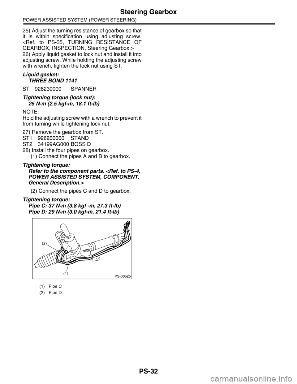
(2) Connect the pipes C and D to gearbox.
Tightening torque:
Pipe C: 37 N·m (3.8 kgf -m, 27.3 ft-lb)
Pipe D: 29 N·m (3.0 kgf-m, 21.4 ft-lb)
(1) Pipe C
(2) Pipe D
PS-00525(1)
(2)
Page 913 of 2453

PS-33
Steering Gearbox
POWER ASSISTED SYSTEM (POWER STEERING)
E: INSPECTION
1. BASIC INSPECTION
1) Clean all the disassembled parts, and check for wear, damage or any other faults, then repair or replace
as necessary.
2) When disassembling, check the inside of gearbox for water. If any water is found, carefully check the boot
for damage, input shaft dust seal, adjusting screw and boot clips for poor sealing. If faulty, replace with new
parts.
No. Parts Inspection Corrective action
1Input shaft(1) Bent input shaft
(2) Damage on serration
If the bend or damage is excessive, replace the entire
gearbox.
2Dust seal(1) Crack or damage
(2) Wear
If the outer wall slips, the lip is worn out or damage is
found, replace it with a new one.
3Rack & pinion Poor mating of rack with pinion
(1) Adjust the backlash properly.
By measuring the turning torque of the gearbox and slid-
ing resistance of rack, check if the rack & pinion engage
uniformly and smoothly with each other. (Refer to “Ser-
vice limit”.)
(2) Pull out the entire rack to allow viewing of the teeth,
and check for damage.
Even if abnormality is found in either (1) or (2), replace
the entire gearbox.
4Gearbox unit
(1) Bending of the rack shaft
(2) Bending of the cylinder portion
(3) Crack or damage on the cast
iron portion
Replace the gearbox with a new one.
(4) Wear or damage on rack bush-
ing
If the free play of rack shaft in radial direction is out of the
specified range, replace the gearbox with new one. (Refer
to “Service limit”.)
(5) Wear on input shaft bearing
If the free play of input shaft in radial and axial direction is
out of the specified range, replace the gearbox with a new
one. (Refer to “Service limit”.)
5Boot Crack, damage or deteriorationReplace.
6Tie–rod(1) Looseness of ball joint
(2) Bend of tie–rodReplace.
7Tie–rod endDamage or deterioration of dust
sealReplace.
8Adjusting screw
springDeterioration Replace.
9Boot clip Deterioration Replace.
10 Sleeve Damage Replace.
11 Pipe
(1) Damage to flared surface
(2) Damage to flare nut
(3) Damage to pipe
Replace.
Page 918 of 2453

PS-38
Pipe Assembly
POWER ASSISTED SYSTEM (POWER STEERING)
7) Disconnect the suction hose and pressure hose
from oil pump.
8) Disconnect the suction hose and return hose
from the reservoir tank.
9) Remove the oil cooler pipe.
10) Remove the hose bracket and take out the
hose assembly from vehicle.
B: INSTALLATION
1) Install in the reverse order of removal.
Tightening torque:
2) Fill with the specified fluid.
CAUTION:
Never start the engine before feeding the fluid
otherwise the vane pump might be seized.
3) Finally, check the clearance between pipes or
hoses as shown in the figure indicated in “General
Diagnostic Table”.
nostic Table.>
(1) Suction hose
(2) Pressure hose
(1) Reservoir tank
(2) Suction hose
(3) Return hose
PS-00736
(1)
(2)
PS-00737(3)
(2)
(1)
(1) Hose ASSY
(2) Hose bracket
PS-00738
PS-00739
(2)
(1)
Page 919 of 2453

PS-39
Pipe Assembly
POWER ASSISTED SYSTEM (POWER STEERING)
C: INSPECTION
Check all disassembled parts for wear, damage or other problems. Repair or replace the defective parts as
necessary.
CAUTION:
Although the surface layer materials of rubber hoses have excellent weathering resistance, heat re-
sistance and resistance for low temperature brittleness, they are likely to be damaged chemically by
brake fluid, battery electrolyte, engine oil and automatic transmission fluid and their service lives are
to be very shortened. Wipe off hoses immediately if any of these come into contact with the hoses.
Since resistances for heat or low temperature brittleness are gradually declining according to time
accumulation of hot or cold conditions for the hoses and their service lives are shortening accord-
ingly, it is necessary to perform careful inspection frequently when the vehicle is used in hot weather
areas, cold weather areas and a driving condition in which many steering operations are required in
short time.
Particularly continuous work of relief valve over 5 seconds causes to reduce service lives of the hos-
es, the oil pump, the fluid, etc. due to over heat.
Par t Maintenance par ts Corrective action
Pipe
•O–ring fitting surface damage
•Nut damage
•Pipe damage
Replace with a new part.
Clamp • Loose clamps Replace with a new part.
Hose
•Flare surface damage
•Flare nut damage
•Outer surface cracks
•Outer surface wear
•Clip damage
•End coupling or adapter for deformation
Replace with a new part.
Tr o u b l e P o s s i b l e c a u s e C o r r e c t i v e a c t i o n
Pressure hose burst
Excessive holding time of relief status Instruct customers.
Malfunction of the relief valve Replace the oil pump.
Poor cold character istic of fluid R eplace fluid.
Disconnection of the return
hose
Improper connection Repair.
Loosening of the clip Retighten.
Poor cold character istic of fluid R eplace fluid.
Fluid slightly leaking out of
hose
Wrong layout, tensioned Replace the hose.
Excessive play of engine due to deterioration of
engine mounting rubberReplace the parts if defective.
Improper stop position of pitching stopper Replace the parts if defective.
Crack on hose
Excessive holding time of relief statusReplace.
Instruct customers.
Excessive tightening torque for return hose clip Replace.
Power steer ing fluid, engine oil, electrolyte adhere
on the hose surface
Replace.
Be careful during service work.
To o m a n y u s e s i n e x t r e m e l y c o l d w e a t h e rReplace.
Instruct customers.
Page 921 of 2453

PS-41
Oil Pump
POWER ASSISTED SYSTEM (POWER STEERING)
7. Oil Pump
A: REMOVAL
1) Disconnect the ground cable from the battery.
2) Remove the air intake duct.
3) Remove the pulley belt cover.
4) Remove the V-belts.
5) Disconnect the connector from power steering
pump switch.
6) Disconnect the pressure hose and suction hose
from power steering pump.
CAUTION:
•Do not spill power steering fluid.
•To prevent foreign matter from entering the
hose and pipe, cover the open ends with clean
cloth.
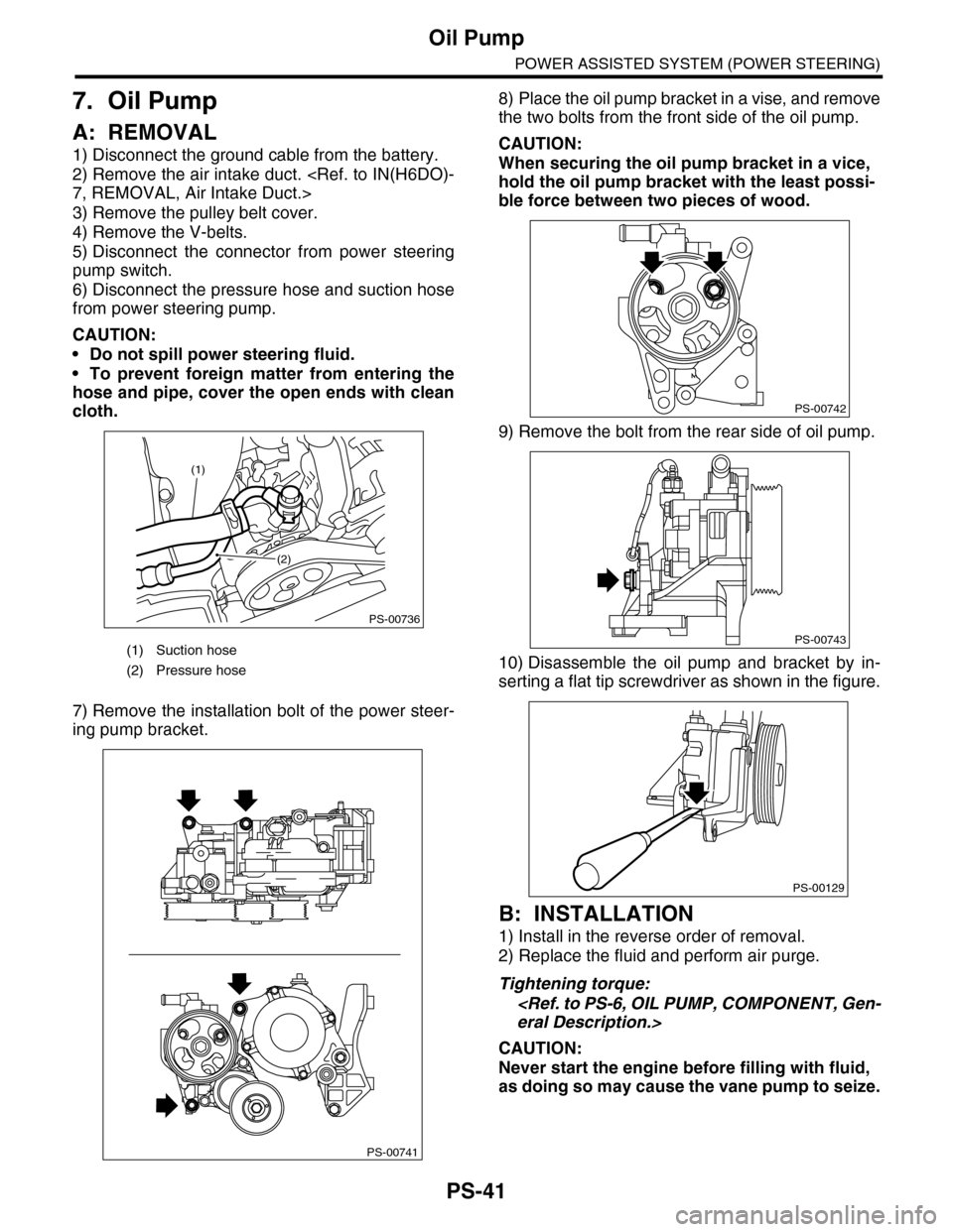
7) Remove the installation bolt of the power steer-
ing pump bracket.
8) Place the oil pump bracket in a vise, and remove
the two bolts from the front side of the oil pump.
CAUTION:
When securing the oil pump bracket in a vice,
hold the oil pump bracket with the least possi-
ble force between two pieces of wood.
9) Remove the bolt from the rear side of oil pump.
10) Disassemble the oil pump and bracket by in-
serting a flat tip screwdriver as shown in the figure.
B: INSTALLATION
1) Install in the reverse order of removal.
2) Replace the fluid and perform air purge.
Tightening torque:
CAUTION:
Never start the engine before filling with fluid,
as doing so may cause the vane pump to seize.
(1) Suction hose
(2) Pressure hose
PS-00736
(1)
(2)
PS-00741
PS-00742
PS-00743
PS-00129
Page 923 of 2453

PS-43
Oil Pump
POWER ASSISTED SYSTEM (POWER STEERING)
3) Temporarily tighten the rear cover to the front
body.
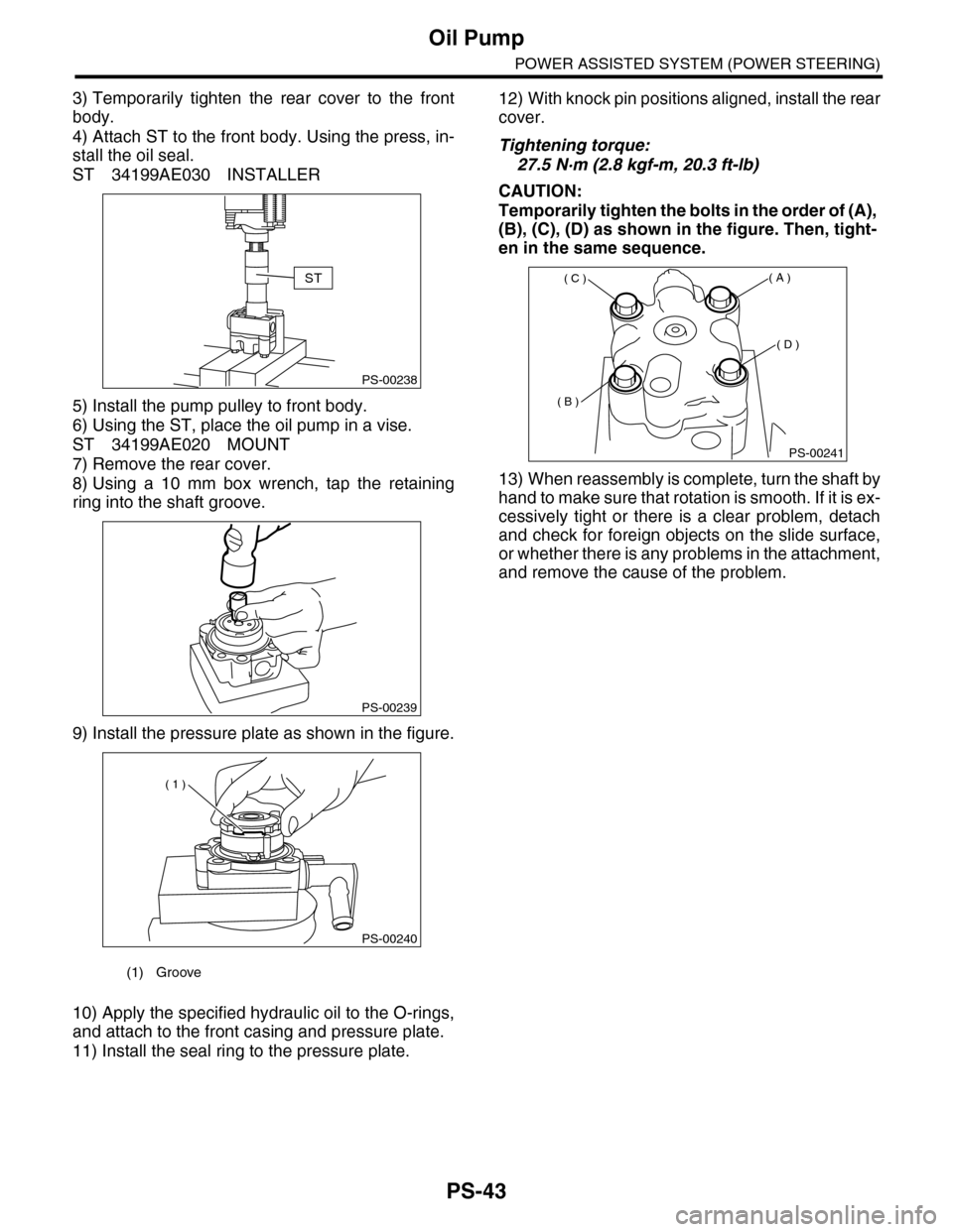
4) Attach ST to the front body. Using the press, in-
stall the oil seal.
ST 34199AE030 INSTALLER
5) Install the pump pulley to front body.
6) Using the ST, place the oil pump in a vise.
ST 34199AE020 MOUNT
7) Remove the rear cover.
8) Using a 10 mm box wrench, tap the retaining
ring into the shaft groove.
9) Install the pressure plate as shown in the figure.
10) Apply the specified hydraulic oil to the O-rings,
and attach to the front casing and pressure plate.
11) Install the seal ring to the pressure plate.
12) With knock pin positions aligned, install the rear
cover.
Tightening torque:
27.5 N·m (2.8 kgf-m, 20.3 ft-lb)
CAUTION:
Temporarily tighten the bolts in the order of (A),
(B), (C), (D) as shown in the figure. Then, tight-
en in the same sequence.
13) When reassembly is complete, turn the shaft by
hand to make sure that rotation is smooth. If it is ex-
cessively tight or there is a clear problem, detach
and check for foreign objects on the slide surface,
or whether there is any problems in the attachment,
and remove the cause of the problem.
(1) Groove
PS-00238
ST
PS-00239
PS-00240
( 1 )
PS-00241
( A )
( B )
( C )
( D )
Page 927 of 2453

PS-47
Reservoir Tank
POWER ASSISTED SYSTEM (POWER STEERING)
8. Reservoir Tank
A: REMOVAL
1) Drain fluid from the reservoir tank.
2) Disconnect the hose from reservoir tank.
CAUTION:
To prevent foreign matter from entering the
hose and pipe, cover the open ends of them
with clean cloth.
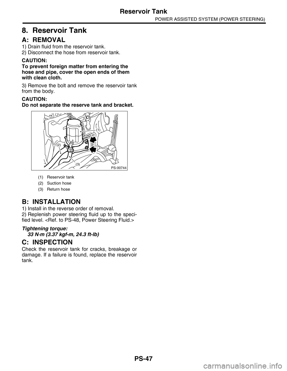
3) Remove the bolt and remove the reservoir tank
from the body.
CAUTION:
Do not separate the reserve tank and bracket.
B: INSTALLATION
1) Install in the reverse order of removal.
2) Replenish power steering fluid up to the speci-
fied level.
Tightening torque:
33 N·m (3.37 kgf-m, 24.3 ft-lb)
C: INSPECTION
Check the reservoir tank for cracks, breakage or
damage. If a failure is found, replace the reservoir
tank.
(1) Reservoir tank
(2) Suction hose
(3) Return hose
PS-00744(3)
(2)
(1)
Page 932 of 2453

PS-52
General Diagnostic Table
POWER ASSISTED SYSTEM (POWER STEERING)
2. MEASUREMENT OF STEERING EFFORT
Step Check Yes No
1CHECK STEERING EFFORT.
1) Stop the vehicle on paved road.
2) Start the engine.
3) Run the engine at idle.
4) Install a spring scale on the steering wheel.
5) Pull the spring scale at a right angle to the
steering wheel, and measure both right and left
steering wheel efforts.
NOTE:When turning the steering more quickly than
necessary from a direction to the other direction
at an engine speed over 2,000 rpm, steering ef-
fort may be heavy. This is caused by flow char-
acteristic of the fluid in the oil pump and is not a
defect.
Is the steering effort less than
29.4 N (3.0 kgf, 6.6 lb)?
Go to step 2.Adjust the back-
lash.
2CHECK STEERING EFFORT.
1) Stop the engine.
2) Pull the spring scale at a right angle to the
steering wheel, and measure both right and left
steering wheel efforts.
Is the steering effort less than
294.2 N (30 kgf, 66.2 lb)?
Go to step 3.Perform the
adjustment.
3CHECK STEERING WHEEL EFFORT.
1) Remove the universal joint.
2) Measure the steering wheel effort.
Is steering effort less than 2.26
N (0.23 kgf, 0.51 lb)?
Go to step 4.Check, adjust and
replace if neces-
sary.
4CHECK STEERING WHEEL EFFORT.
Measure the steering wheel effort.
Is the difference of steering
effort between right and left
less than 20%?
Go to step 5.Check, adjust and
replace if neces-
sary.
5CHECK UNIVERSAL JOINT.
Measure the swing torque of the joint (yoke of
steering column side).
Is the swing torque of the uni-
versal joint less than 7.3 N
(0.74 kgf, 1.64 lb)?
Go to step 6.Replace with a
new part.
6CHECK UNIVERSAL JOINT.
Measure the swing torque of the joint (yoke of
gearbox side).
Is the swing torque of the uni-
versal joint less than 3.8 N
(0.39 kgf, 0.86 lb)?
Go to step 7.Replace with a
new part.
7CHECK FRONT WHEEL.
Check the front wheels.
Does the front wheels have
unsteady revolution or rattling,
or does the brake drag?
Inspect, readjust
and replace if nec-
essary.
Go to step 8.
8CHECK TIE–ROD ENDS.
Remove the tie–rod ends.
If the tie-rod ends of suspen-
sion have unsteady revolution
or rattling?
Inspect and
replace if neces-
sary.
Go to step 9.
9BALL JOINT CHECK.
Remove the ball joint.
If the ball joints of suspension
have unsteady revolution or
rattling?
Inspect and
replace if neces-
sary.
Go to step 10.
10 CHECK GEARBOX.
Measure the rotating of gearbox.
box.>
Is the rotating resistance of
steering gearbox less than
10.5 N (1.1 kgf, 2.4 lb)? Is the
difference between right and
left sides less than 20%?
Go to step 11.Readjust the back-
lash, and if ineffec-
tive, replace the
faulty par ts.
11 CHECK GEARBOX.
Measure the sliding of gearbox.
Is the sliding resistance of
steering gearbox less than 400
N (41 kgf, 90 lb)? Is the differ-
ence between the right and left
sliding resistance less than
20%?
Steering effort is
normal.
Readjust the back-
lash, and if ineffec-
tive, replace the
faulty par ts.