Page 949 of 2453

RS-16
Rear Sub Frame
REAR SUSPENSION
9. Rear Sub Frame
A: REMOVAL
1) Separate the front exhaust pipe and rear ex-
haust pipe.
2) Remove the rear exhaust pipe and muffler.
3) Remove the propeller shaft.
4) Remove the spare tire hoist.
REMOVAL, Spare Tire Hoist.>
5) Remove the rear parking brake cable from the
parking brake assembly.
AL, Parking Brake Assembly (Rear Disc Brake).>
6) Detach the brake hose, and remove the rear
brake caliper from the vehicle.
7) Disconnect the ABS wheel speed sensor con-
nector.
8) Remove the bolts on the bottom side of the
shock absorber.
9) Support the sub frame using a jack.
10) Remove the front sub frame.
11) Remove the rear sub frame support.
12) Remove the rear sub frame.
B: INSTALLATION
NOTE:
•Be sure to use a new self-locking nut.
•Always tighten the stabilizer bushing in the state
where the vehicle is at curb weight and the wheels
are in full contact with the ground.
1) Install in the reverse order of removal.
Tightening torque:
Refer to “COMPONENT” of “General Descrip-
tion” for the tightening torque.
COMPONENT, General Description.>
2) Bleed air from brake system.
3) Inspect the wheel alignment and adjust if neces-
sary.
C: INSPECTION
Check the removed parts for wear, damage and
crack, and repair or replace them if faulty.
RS-00194
RS-00195
RS-00196
RS-00197
RS-00198
Page 950 of 2453

RS-17
General Diagnostic Table
REAR SUSPENSION
10.General Diagnostic Table
A: INSPECTION
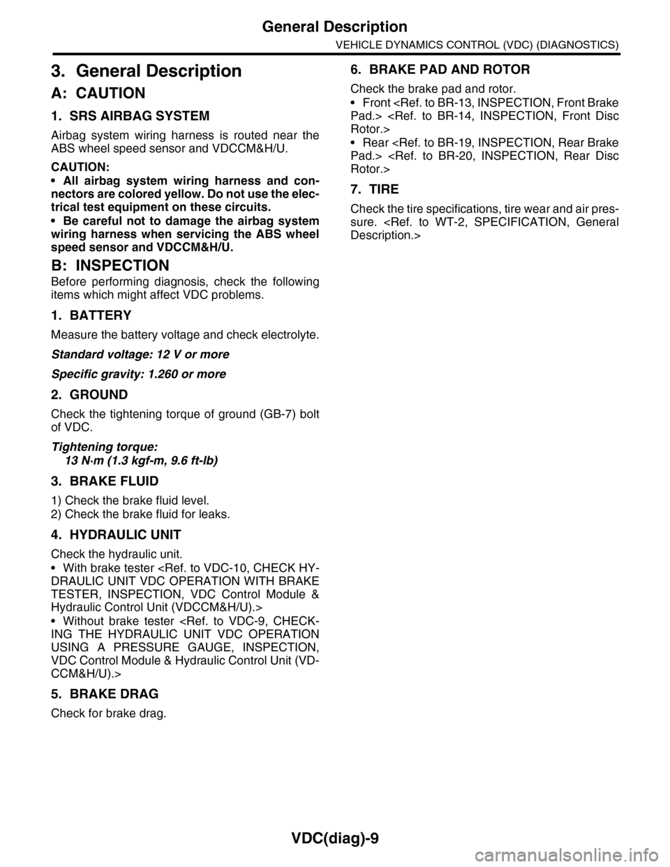
1. IMPROPER VEHICLE POSTURE OR IMPROPER WHEEL ARCH HEIGHT
2. POOR RIDE COMFORT
1) Large rebound shock
2) Rocking of the vehicle continues too long after running over bump and hump.
3) Excessive shock in bumping
3. NOISE
Po ss ibl e c a us e C o r r e ct ive ac ti o n
(1) Permanent distortion or damaged coil spring Replace.
(2) Rough operation of damper strut or shock absorber Replace.
(3) Improper installation of strut or shock absorber Replace with proper parts.
(4) Installation of the wrong coil spring Replace with proper parts.
Po ss ibl e ca us e C or r e ct i ve a ct io n
(1) Damaged coil spring Replace.
(2) Overinflation of tires Adjust.
(3) Improper wheel arch height Adjust or replace the coil springs with new ones.
(4) Fault in operation of damper strut or shock absorber Replace.
(5) Damage or deformation of strut mount or shock absorber mount Replace.
(6) Unsuitable length (maximum or minimum) of damper strut or shock
absorber
Replace with appropriate parts.
(7) Deformation or loss of bushing Replace.
(8) Deformation or damage of helper in strut assembly or shock absorber Replace.
(9) Oil leakage from the damper strut or shock absorber Replace.
Po ss ibl e c a us e C o r r e ct ive ac ti o n
(1) Wear or damage of damper strut or shock absorber component parts Replace.
(2) Loosening of the suspension link installing bolt Tighten to the specified torque.
(3) Deformation or loss of bushing Replace.
(4) Unsuitable length (maximum or minimum) of damper strut or shock
absorber
Replace with appropriate parts.
(5) Damaged coil spring Replace.
(6) Wear or damage of the ball joint Replace.
(7) Deformation of the stabilizer clamp Replace.
Page 1001 of 2453

VDC(diag)-9
General Description
VEHICLE DYNAMICS CONTROL (VDC) (DIAGNOSTICS)
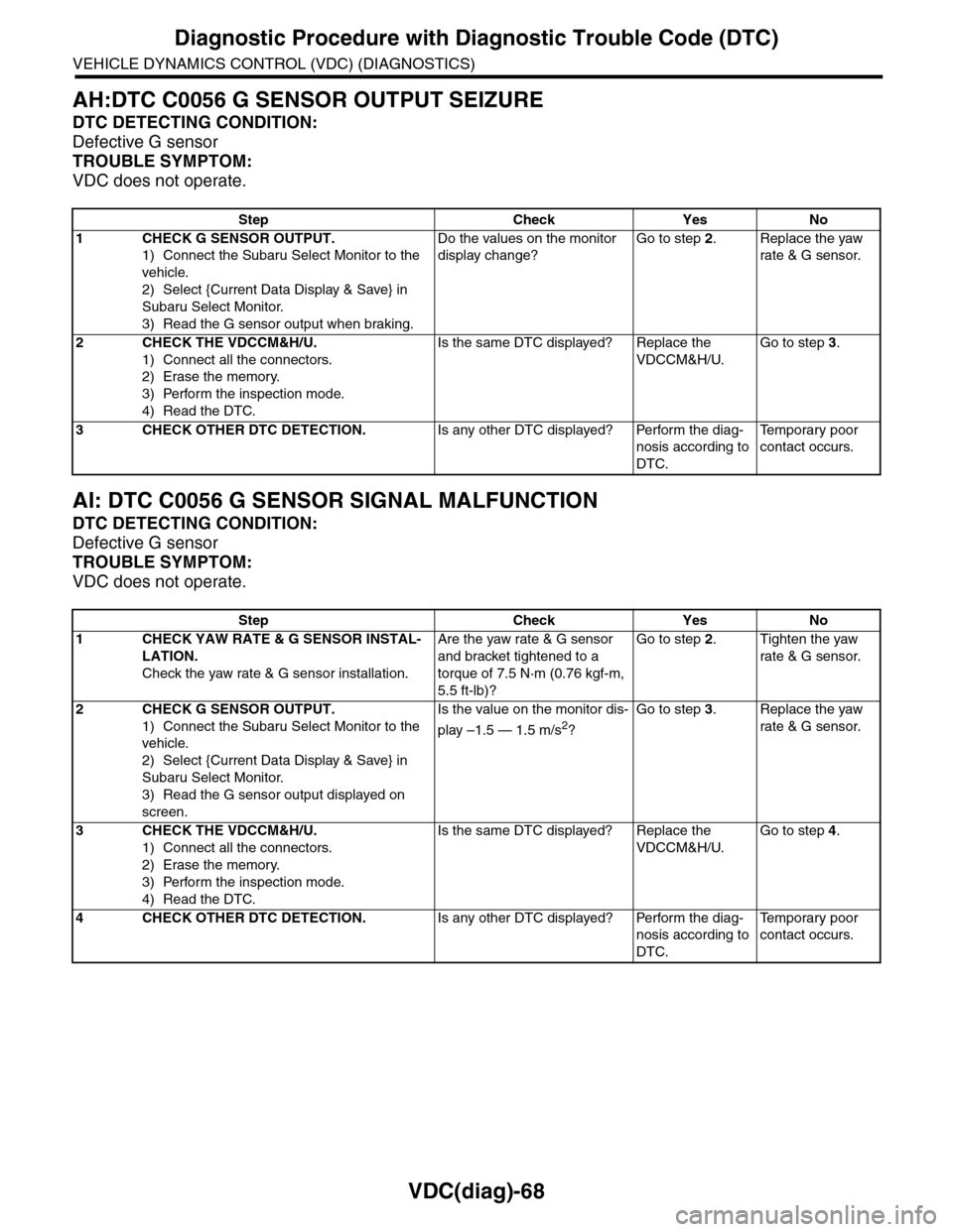
3. General Description
A: CAUTION
1. SRS AIRBAG SYSTEM
Airbag system wiring harness is routed near the
ABS wheel speed sensor and VDCCM&H/U.
CAUTION:
•All airbag system wiring harness and con-
nectors are colored yellow. Do not use the elec-
trical test equipment on these circuits.
•Be careful not to damage the airbag system
wiring harness when servicing the ABS wheel
speed sensor and VDCCM&H/U.
B: INSPECTION
Before performing diagnosis, check the following
items which might affect VDC problems.
1. BATTERY
Measure the battery voltage and check electrolyte.
Standard voltage: 12 V or more
Specific gravity: 1.260 or more
2. GROUND
Check the tightening torque of ground (GB-7) bolt
of VDC.
Tightening torque:
13 N·m (1.3 kgf-m, 9.6 ft-lb)
3. BRAKE FLUID
1) Check the brake fluid level.
2) Check the brake fluid for leaks.
4. HYDRAULIC UNIT
Check the hydraulic unit.
•With brake tester
DRAULIC UNIT VDC OPERATION WITH BRAKE
TESTER, INSPECTION, VDC Control Module &
Hydraulic Control Unit (VDCCM&H/U).>
•Without brake tester
ING THE HYDRAULIC UNIT VDC OPERATION
USING A PRESSURE GAUGE, INSPECTION,
VDC Control Module & Hydraulic Control Unit (VD-
CCM&H/U).>
5. BRAKE DRAG
Check for brake drag.
6. BRAKE PAD AND ROTOR
Check the brake pad and rotor.
•Front
Pad.>
Rotor.>
•Rear
Pad.>
Rotor.>
7. TIRE
Check the tire specifications, tire wear and air pres-
sure.
Description.>
Page 1060 of 2453

VDC(diag)-68
Diagnostic Procedure with Diagnostic Trouble Code (DTC)
VEHICLE DYNAMICS CONTROL (VDC) (DIAGNOSTICS)
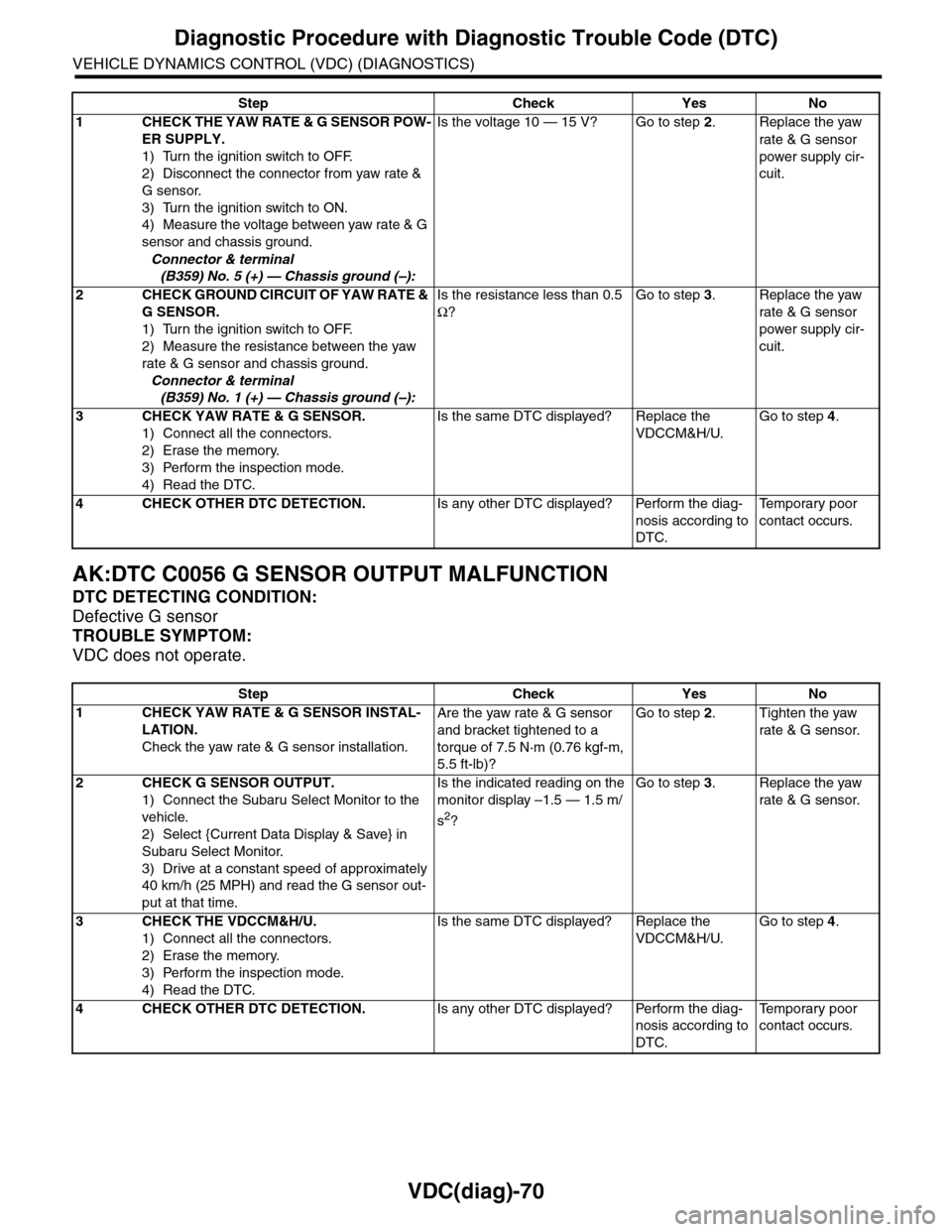
AH:DTC C0056 G SENSOR OUTPUT SEIZURE
DTC DETECTING CONDITION:
Defective G sensor
TROUBLE SYMPTOM:
VDC does not operate.
AI: DTC C0056 G SENSOR SIGNAL MALFUNCTION
DTC DETECTING CONDITION:
Defective G sensor
TROUBLE SYMPTOM:
VDC does not operate.
Step Check Yes No
1CHECK G SENSOR OUTPUT.
1) Connect the Subaru Select Monitor to the
vehicle.
2) Select {Current Data Display & Save} in
Subaru Select Monitor.
3) Read the G sensor output when braking.
Do the values on the monitor
display change?
Go to step 2.Replace the yaw
rate & G sensor.
2CHECK THE VDCCM&H/U.
1) Connect all the connectors.
2) Erase the memory.
3) Perform the inspection mode.
4) Read the DTC.
Is the same DTC displayed? Replace the
VDCCM&H/U.
Go to step 3.
3CHECK OTHER DTC DETECTION.Is any other DTC displayed? Perform the diag-
nosis according to
DTC.
Te m p o r a r y p o o r
contact occurs.
Step Check Yes No
1CHECK YAW RATE & G SENSOR INSTAL-
LATION.
Check the yaw rate & G sensor installation.
Are the yaw rate & G sensor
and bracket tightened to a
torque of 7.5 N·m (0.76 kgf-m,
5.5 ft-lb)?
Go to step 2.Tighten the yaw
rate & G sensor.
2CHECK G SENSOR OUTPUT.
1) Connect the Subaru Select Monitor to the
vehicle.
2) Select {Current Data Display & Save} in
Subaru Select Monitor.
3) Read the G sensor output displayed on
screen.
Is the value on the monitor dis-
play –1.5 — 1.5 m/s2?
Go to step 3.Replace the yaw
rate & G sensor.
3CHECK THE VDCCM&H/U.
1) Connect all the connectors.
2) Erase the memory.
3) Perform the inspection mode.
4) Read the DTC.
Is the same DTC displayed? Replace the
VDCCM&H/U.
Go to step 4.
4CHECK OTHER DTC DETECTION.Is any other DTC displayed? Perform the diag-
nosis according to
DTC.
Te m p o r a r y p o o r
contact occurs.
Page 1062 of 2453

VDC(diag)-70
Diagnostic Procedure with Diagnostic Trouble Code (DTC)
VEHICLE DYNAMICS CONTROL (VDC) (DIAGNOSTICS)
AK:DTC C0056 G SENSOR OUTPUT MALFUNCTION
DTC DETECTING CONDITION:
Defective G sensor
TROUBLE SYMPTOM:
VDC does not operate.
Step Check Yes No
1CHECK THE YAW RATE & G SENSOR POW-
ER SUPPLY.
1) Turn the ignition switch to OFF.
2) Disconnect the connector from yaw rate &
G sensor.
3) Turn the ignition switch to ON.
4) Measure the voltage between yaw rate & G
sensor and chassis ground.
Connector & terminal
(B359) No. 5 (+) — Chassis ground (–):
Is the voltage 10 — 15 V? Go to step 2.Replace the yaw
rate & G sensor
power supply cir-
cuit.
2CHECK GROUND CIRCUIT OF YAW RATE &
G SENSOR.
1) Turn the ignition switch to OFF.
2) Measure the resistance between the yaw
rate & G sensor and chassis ground.
Connector & terminal
(B359) No. 1 (+) — Chassis ground (–):
Is the resistance less than 0.5
Ω?
Go to step 3.Replace the yaw
rate & G sensor
power supply cir-
cuit.
3CHECK YAW RATE & G SENSOR.
1) Connect all the connectors.
2) Erase the memory.
3) Perform the inspection mode.
4) Read the DTC.
Is the same DTC displayed? Replace the
VDCCM&H/U.
Go to step 4.
4CHECK OTHER DTC DETECTION.Is any other DTC displayed? Perform the diag-
nosis according to
DTC.
Te m p o r a r y p o o r
contact occurs.
Step Check Yes No
1CHECK YAW RATE & G SENSOR INSTAL-
LATION.
Check the yaw rate & G sensor installation.
Are the yaw rate & G sensor
and bracket tightened to a
torque of 7.5 N·m (0.76 kgf-m,
5.5 ft-lb)?
Go to step 2.Tighten the yaw
rate & G sensor.
2CHECK G SENSOR OUTPUT.
1) Connect the Subaru Select Monitor to the
vehicle.
2) Select {Current Data Display & Save} in
Subaru Select Monitor.
3) Drive at a constant speed of approximately
40 km/h (25 MPH) and read the G sensor out-
put at that time.
Is the indicated reading on the
monitor display –1.5 — 1.5 m/
s2?
Go to step 3.Replace the yaw
rate & G sensor.
3CHECK THE VDCCM&H/U.
1) Connect all the connectors.
2) Erase the memory.
3) Perform the inspection mode.
4) Read the DTC.
Is the same DTC displayed? Replace the
VDCCM&H/U.
Go to step 4.
4CHECK OTHER DTC DETECTION.Is any other DTC displayed? Perform the diag-
nosis according to
DTC.
Te m p o r a r y p o o r
contact occurs.
Page 1083 of 2453
VDC-2
General Description
VEHICLE DYNAMICS CONTROL (VDC)
1. General Description
A: SPECIFICATION
B: COMPONENT
1. ABS WHEEL SPEED SENSOR
Item Specification or identification
ABS wheel speed
sensor
ABS wheel speed sensor
gap (for reference)
Fr o nt 0 . 55 — 1. 4 5 m m ( 0. 0 2 2 — 0. 0 57 i n)
Rear 0.50 — 1.50 mm (0.020 — 0.059 in)
Identifications of harness
(marks, color)
Fr o nt W1 ( Wh i te )
Rear W3 (White)
VDCCM&H/U IdentificationW1
(1) Front ABS wheel speed sensor (4) Hub unit bearingTightening torque: N·m (kgf-m, ft-lb)
(2) Front housing (5) Magnetic encoderT: 7.5 (0.76, 5.5)
(3) Rear ABS wheel speed sensor
VDC00340
T
T
(3)
(4)
(5)
(2)
(1)
Page 1084 of 2453
VDC-3
General Description
VEHICLE DYNAMICS CONTROL (VDC)
2. YAW RATE & LATERAL G SENSOR
3. STEERING ANGLE SENSOR
(1) Yaw rate & lateral G sensor Tightening torque: N·m (kgf-m, ft-lb)
(2) Bracket T: 7.5 (0.76, 5.5)
VDC00341
(1)
T
T
(2)
(1) Steering angle sensor
VDC00196
(1)
Page 1085 of 2453
VDC-4
General Description
VEHICLE DYNAMICS CONTROL (VDC)
4. VDC CONTROL MODULE AND HYDRAULIC CONTROL UNIT (VDCCM&H/U)
(1) VDC control module and hydraulic
control unit (VDCCM&H/U)
(5) Secondary inlet (10) Stud bolt
(6) Primary inlet
(2) Bracket (7) Front LH outletTightening torque: N·m (kgf-m, ft-lb)
(3) Rear RH outlet (8) Front RH outletT1: 7.5 (0.76, 5.5)
(4) Rear LH outlet (9) DamperT2: 33 (3.4, 24)