2009 SUBARU TRIBECA torque
[x] Cancel search: torquePage 896 of 2453

PS-16
Tilt Steering Column
POWER ASSISTED SYSTEM (POWER STEERING)
B: INSTALLATION
1) Insert the end of the steering shaft into the toe
board.
2) With the tilt lever secured, tighten the steering
shaft mounting bolts under instrument panel.
Tightening torque:
25 N·m (2.5 kgf-m, 18.1 ft-lb)
3) Connect all the connectors under the instrument
panel.
4) Connect the airbag system connector at the har-
ness spool.
NOTE:
Make sure to apply double lock.
5) Install the instrument panel lower cover with tilt
lever held in the lowered position.
6) Install the universal joint.
7) Align the center position of the roll connector.
8) Install the steering wheel.
CAUTION:
Insert the roll connector guide pin into the
guide hole on lower end of steering wheel sur-
face to prevent damage.
C: DISASSEMBLY
Remove the two screws securing the upper steer-
ing column covers, and the two screws securing
the combination switch, and then remove related
parts.
D: ASSEMBLY
Insert the combination switch to the upper column
shaft, and install the upper column cover. Then
route the ignition key harness and combination
switch harness between the column cover mount-
ing bosses.
Tightening torque:
1.2 N·m (0.12 kgf-m, 0.9 ft-lb)
CAUTION:
Do not overtorque the screw.
E: INSPECTION
1. BASIC INSPECTION
Measure the overall length of steering column. If
not within specification, replace it.
Overall length L:
Specification
917.5 +1.3 mm –0.3 mm (36.12 +0.051 in –0.020 in )
2. INSPECTION OF AIRBAG SYSTEM
WARNING:
Refer to “Airbag System” for airbag inspection
procedure.
PS-00734
L
Page 898 of 2453

PS-18
Steering Gearbox
POWER ASSISTED SYSTEM (POWER STEERING)
11) Remove the gear box bracket and clamp, and
remove the gearbox.
B: INSTALLATION
1) Insert the gearbox into crossmember, being
careful not to damage gearbox boot.
2) Attach the gearbox bracket and clamp.
Tightening torque:
60 N·m (6.1 kgf-m, 44.1 ft-lb)
3) Connect the pipe D to return hose first, and the
pipe C to pressure hose second.
Tightening torque:
15 N·m (1.5 kgf -m, 10.8 ft-lb)
4) Install the universal joint.
5) Connect the tie–rod end and knuckle arm, and
tighten with castle nut.
Castle nut tightening torque:
27 N·m (2.75 kgf-m, 19.9 ft-lb)
CAUTION:
When connecting, do not hit the cap at the bot-
tom of tie–rod end with hammer.
(1) Bracket
(2) Clamp
(1) Bracket
(2) Clamp
PS-00735
(2)(1)
PS-00735
(2)(1)
(1) Pipe C
(2) Pipe D
(3) Pressure hose
(4) Return hose
PS-00538
(4)
(3)
(2)
(1)
Page 899 of 2453

PS-19
Steering Gearbox
POWER ASSISTED SYSTEM (POWER STEERING)
6) After tightening the castle nut to the specified
tightening torque, tighten it further within 60° until
the cotter pin hole is aligned with slot in the nut. Fit
the cotter pin into the nut, and then bend the pin to
lock.
7) Install the front stabilizer.
8) Install the front crossmember support plate and
jack-up plate.
9) Install the front exhaust pipe assembly. (Non–
turbo model)
10) Install the under cover.
11) Install the front wheels.
12) Tighten the wheel nuts to the specified torque.
Tightening torque:
110 N·m (11.2 kgf-m, 81.1 ft-lb)
13) Lower the vehicle.
14) Remove the steering wheel.
15) Align the center position of the roll connector.
16) Install the steering wheel.
17) Connect the ground cable to the battery.
18) Pour fluid into the oil tank, and bleed air.
19) Check for fluid leaks.
20) Check the fluid level in oil tank.
21) After adjusting toe-in and steering angle, tight-
en the lock nut on tie-rod end.
Tightening torque:
85 N·m (8.7 kgf-m, 62.7 ft-lb)
NOTE:
When adjusting toe-in, hold the boot as shown to
prevent it from being rotated or twisted. If it be-
comes twisted, straighten it.
C: DISASSEMBLY
1. RACK HOUSING ASSEMBLY
1) Disconnect the four pipes from gearbox.
NOTE:
Remove the pipes C and D, which are fixed to
clamp plate, as a unit.
2) Secure the gearbox removed from vehicle in a
vise using ST.
ST1 926200000 STAND
ST2 34199AG000 BOSS D
CAUTION:
Secure the gearbox in a vise using ST as shown
in the figure. Do not secure the gearbox without
this ST.
3) Remove the tie-rod end and lock nut from gear-
box.
(A) Cotter pin
(B) Castle nut
(C) Tie–rod end
DS-00042
(C)
(B)
(A)
(1) Clamp
PS-00051
PS-00492
(1)
ST1
ST2
Page 905 of 2453

PS-25
Steering Gearbox
POWER ASSISTED SYSTEM (POWER STEERING)
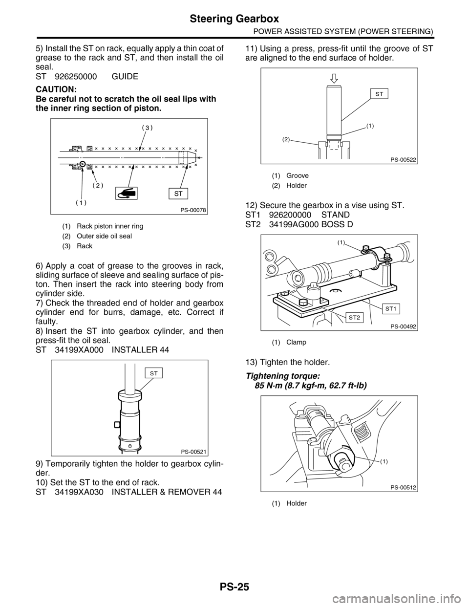
5) Install the ST on rack, equally apply a thin coat of
grease to the rack and ST, and then install the oil
seal.
ST 926250000 GUIDE
CAUTION:
Be careful not to scratch the oil seal lips with
the inner ring section of piston.
6) Apply a coat of grease to the grooves in rack,
sliding surface of sleeve and sealing surface of pis-
ton. Then insert the rack into steering body from
cylinder side.
7) Check the threaded end of holder and gearbox
cylinder end for burrs, damage, etc. Correct if
faulty.
8) Insert the ST into gearbox cylinder, and then
press-fit the oil seal.
ST 34199XA000 INSTALLER 44
9) Temporarily tighten the holder to gearbox cylin-
der.
10) Set the ST to the end of rack.
ST 34199XA030 INSTALLER & REMOVER 44
11) Using a press, press-fit until the groove of ST
are aligned to the end surface of holder.
12) Secure the gearbox in a vise using ST.
ST1 926200000 STAND
ST2 34199AG000 BOSS D
13) Tighten the holder.
Tightening torque:
85 N·m (8.7 kgf-m, 62.7 ft-lb)
(1) Rack piston inner ring
(2) Outer side oil seal
(3) Rack
PS-00078
PS-00521
ST
(1) Groove
(2) Holder
(1) Clamp
(1) Holder
PS-00522
ST
(1)
(2)
PS-00492
(1)
ST1
ST2
PS-00512
(1)
Page 906 of 2453

PS-26
Steering Gearbox
POWER ASSISTED SYSTEM (POWER STEERING)
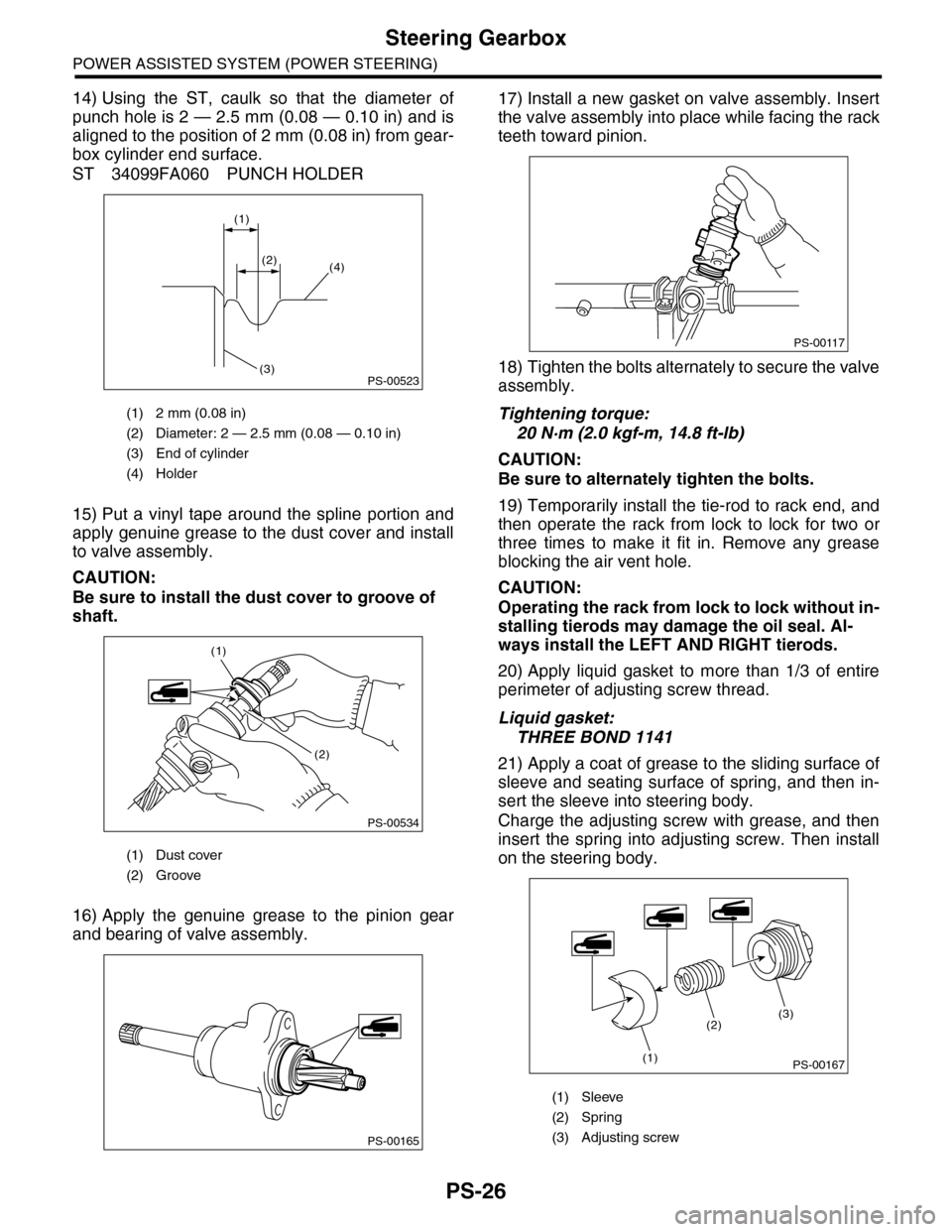
14) Using the ST, caulk so that the diameter of
punch hole is 2 — 2.5 mm (0.08 — 0.10 in) and is
aligned to the position of 2 mm (0.08 in) from gear-
box cylinder end surface.
ST 34099FA060 PUNCH HOLDER
15) Put a vinyl tape around the spline portion and
apply genuine grease to the dust cover and install
to valve assembly.
CAUTION:
Be sure to install the dust cover to groove of
shaft.
16) Apply the genuine grease to the pinion gear
and bearing of valve assembly.
17) Install a new gasket on valve assembly. Insert
the valve assembly into place while facing the rack
teeth toward pinion.
18) Tighten the bolts alternately to secure the valve
assembly.
Tightening torque:
20 N·m (2.0 kgf-m, 14.8 ft-lb)
CAUTION:
Be sure to alternately tighten the bolts.
19) Temporarily install the tie-rod to rack end, and
then operate the rack from lock to lock for two or
three times to make it fit in. Remove any grease
blocking the air vent hole.
CAUTION:
Operating the rack from lock to lock without in-
stalling tierods may damage the oil seal. Al-
ways install the LEFT AND RIGHT tierods.
20) Apply liquid gasket to more than 1/3 of entire
perimeter of adjusting screw thread.
Liquid gasket:
THREE BOND 1141
21) Apply a coat of grease to the sliding surface of
sleeve and seating surface of spring, and then in-
sert the sleeve into steering body.
Charge the adjusting screw with grease, and then
insert the spring into adjusting screw. Then install
on the steering body.
(1) 2 mm (0.08 in)
(2) Diameter: 2 — 2.5 mm (0.08 — 0.10 in)
(3) End of cylinder
(4) Holder
(1) Dust cover
(2) Groove
PS-00523
(1)
(2)(4)
(3)
PS-00534
(1)
(2)
PS-00165
(1) Sleeve
(2) Spring
(3) Adjusting screw
PS-00117
PS-00167
(2)
(1)
(3)
Page 907 of 2453

PS-27
Steering Gearbox
POWER ASSISTED SYSTEM (POWER STEERING)
22) Tighten the adjusting screw to the specified
torque.
Tightening torque:
3.9 N·m (0.4 kgf-m, 2.9 ft-lb)
23) Tighten the adjusting screw to the specified
torque, then loosen it 20°.
24) Remove the tie–rod.
25) Adjust the turning resistance of gearbox so that
it is within specification using adjusting screw.
26) Apply liquid gasket to lock nut and install it into
adjusting screw. While holding the adjusting screw
with wrench, tighten the lock nut using ST.
Liquid gasket:
THREE BOND 1141
ST 926230000 SPANNER
Tightening torque (lock nut):
25 N·m (2.5 kgf-m, 18.1 ft-lb)
NOTE:
Hold the adjusting screw with a wrench to prevent it
from turning while tightening lock nut.
27) Extend the rack approx. 40 mm (1.57 in) from
steering body.
28) Install the tie-rod and new lock washer into
rack.
Tightening torque:
130 N·m (13.3 kgf-m, 95.9 ft-lb)
29) Bend the lock washer and caulk it.
CAUTION:
Be careful not to scratch the rack when caulk-
ing lock washer.
30) Apply a coat of grease to the tie–rod groove,
and then install the boot to the housing.
CAUTION:
Right side boot has groove for identification, be
sure to install the right and left of boot.
(1) Lock washer
(2) Approx. 40 mm (1.57 in)
PS-00439
(2)
(1)
(1) Lock washer
(1) Right side boot
(2) Groove for identification
PS-00093
PS-00524
(2)
(1)
Page 909 of 2453

PS-29
Steering Gearbox
POWER ASSISTED SYSTEM (POWER STEERING)
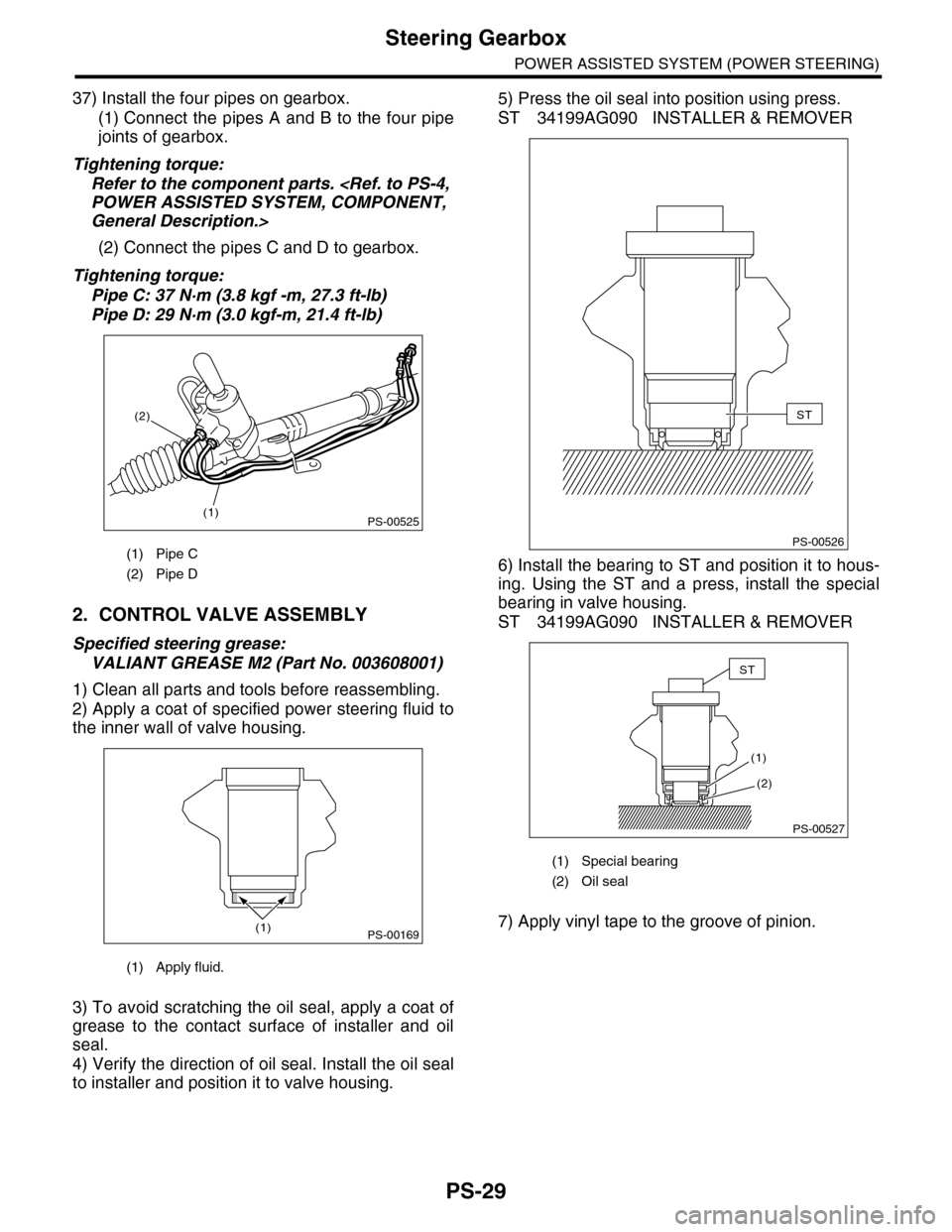
37) Install the four pipes on gearbox.
(1) Connect the pipes A and B to the four pipe
joints of gearbox.
Tightening torque:
Refer to the component parts.
General Description.>
(2) Connect the pipes C and D to gearbox.
Tightening torque:
Pipe C: 37 N·m (3.8 kgf -m, 27.3 ft-lb)
Pipe D: 29 N·m (3.0 kgf-m, 21.4 ft-lb)
2. CONTROL VALVE ASSEMBLY
Specified steering grease:
VALIANT GREASE M2 (Part No. 003608001)
1) Clean all parts and tools before reassembling.
2) Apply a coat of specified power steering fluid to
the inner wall of valve housing.
3) To avoid scratching the oil seal, apply a coat of
grease to the contact surface of installer and oil
seal.
4) Verify the direction of oil seal. Install the oil seal
to installer and position it to valve housing.
5) Press the oil seal into position using press.
ST 34199AG090 INSTALLER & REMOVER
6) Install the bearing to ST and position it to hous-
ing. Using the ST and a press, install the special
bearing in valve housing.
ST 34199AG090 INSTALLER & REMOVER
7) Apply vinyl tape to the groove of pinion.
(1) Pipe C
(2) Pipe D
(1) Apply fluid.
PS-00525(1)
(2)
PS-00169(1)
(1) Special bearing
(2) Oil seal
PS-00526
ST
(2)
(1)
PS-00527
ST
Page 911 of 2453

PS-31
Steering Gearbox
POWER ASSISTED SYSTEM (POWER STEERING)
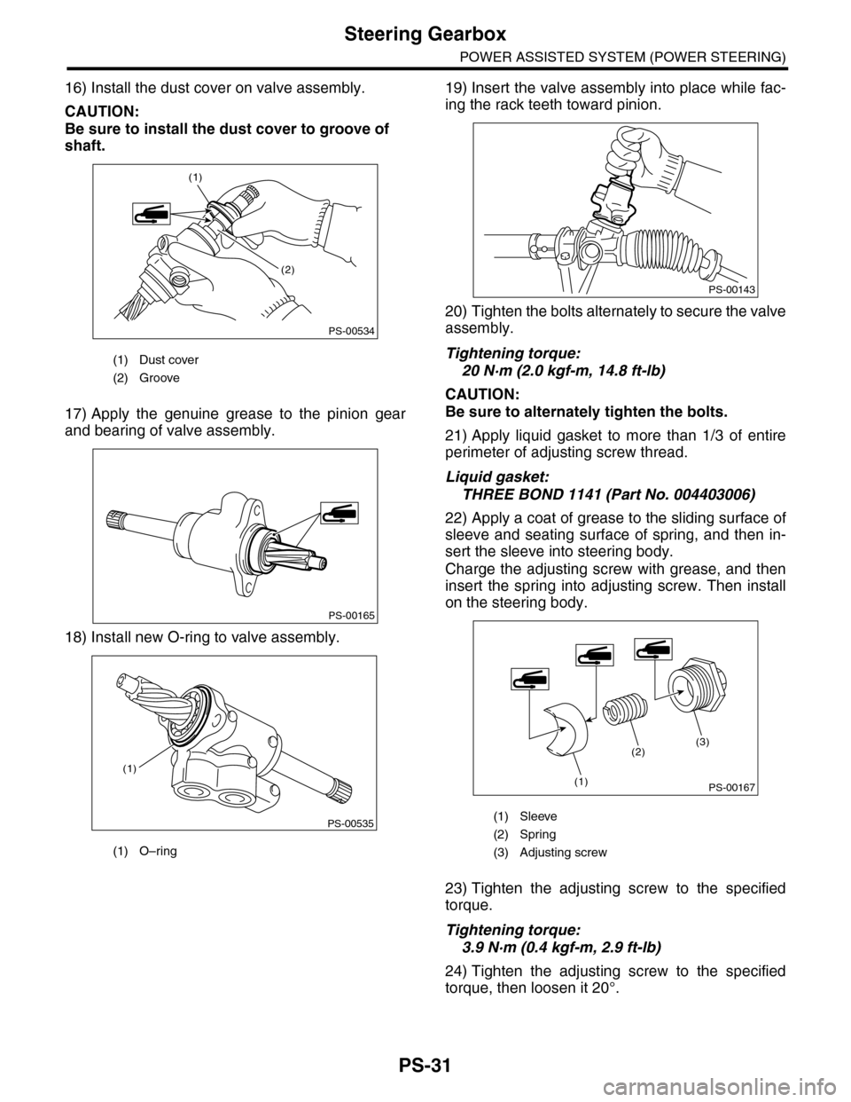
16) Install the dust cover on valve assembly.
CAUTION:
Be sure to install the dust cover to groove of
shaft.
17) Apply the genuine grease to the pinion gear
and bearing of valve assembly.
18) Install new O-ring to valve assembly.
19) Insert the valve assembly into place while fac-
ing the rack teeth toward pinion.
20) Tighten the bolts alternately to secure the valve
assembly.
Tightening torque:
20 N·m (2.0 kgf-m, 14.8 ft-lb)
CAUTION:
Be sure to alternately tighten the bolts.
21) Apply liquid gasket to more than 1/3 of entire
perimeter of adjusting screw thread.
Liquid gasket:
THREE BOND 1141 (Part No. 004403006)
22) Apply a coat of grease to the sliding surface of
sleeve and seating surface of spring, and then in-
sert the sleeve into steering body.
Charge the adjusting screw with grease, and then
insert the spring into adjusting screw. Then install
on the steering body.
23) Tighten the adjusting screw to the specified
torque.
Tightening torque:
3.9 N·m (0.4 kgf-m, 2.9 ft-lb)
24) Tighten the adjusting screw to the specified
torque, then loosen it 20°.
(1) Dust cover
(2) Groove
(1) O–ring
PS-00534
(1)
(2)
PS-00165
PS-00535
(1)
(1) Sleeve
(2) Spring
(3) Adjusting screw
PS-00143
PS-00167
(2)
(1)
(3)