2009 SUBARU TRIBECA torque
[x] Cancel search: torquePage 864 of 2453

FS-16
Front Arm
FRONT SUSPENSION
6. Front Arm
A: REMOVAL
1) Lift-up the vehicle, and then remove the front
wheels.
2) Remove the front crossmember support plate.
3) Remove the front stabilizer.
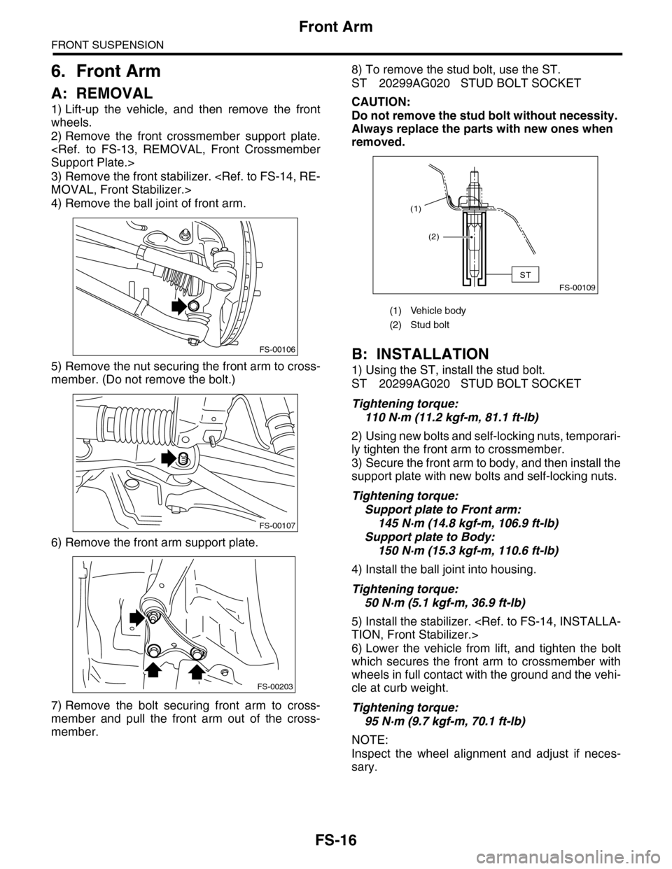
4) Remove the ball joint of front arm.
5) Remove the nut securing the front arm to cross-
member. (Do not remove the bolt.)
6) Remove the front arm support plate.
7) Remove the bolt securing front arm to cross-
member and pull the front arm out of the cross-
member.
8) To remove the stud bolt, use the ST.
ST 20299AG020 STUD BOLT SOCKET
CAUTION:
Do not remove the stud bolt without necessity.
Always replace the parts with new ones when
removed.
B: INSTALLATION
1) Using the ST, install the stud bolt.
ST 20299AG020 STUD BOLT SOCKET
Tightening torque:
110 N·m (11.2 kgf-m, 81.1 ft-lb)
2) Using new bolts and self-locking nuts, temporari-
ly tighten the front arm to crossmember.
3) Secure the front arm to body, and then install the
support plate with new bolts and self-locking nuts.
Tightening torque:
Support plate to Front arm:
145 N·m (14.8 kgf-m, 106.9 ft-lb)
Support plate to Body:
150 N·m (15.3 kgf-m, 110.6 ft-lb)
4) Install the ball joint into housing.
Tightening torque:
50 N·m (5.1 kgf-m, 36.9 ft-lb)
5) Install the stabilizer.
6) Lower the vehicle from lift, and tighten the bolt
which secures the front arm to crossmember with
wheels in full contact with the ground and the vehi-
cle at curb weight.
Tightening torque:
95 N·m (9.7 kgf-m, 70.1 ft-lb)
NOTE:
Inspect the wheel alignment and adjust if neces-
sary.
FS-00106
FS-00107
FS-00203
(1) Vehicle body
(2) Stud bolt
FS-00109
(2)
(1)
ST
Page 867 of 2453

FS-19
Front Strut
FRONT SUSPENSION
7. Front Strut
A: REMOVAL
1) Lift-up the vehicle, and then remove the front
wheels.
2) Place an alignment mark on the camber adjust-
ing bolt and strut.
3) Remove the bolt securing the brake hose from
the strut.
4) Remove the clip securing the ABS wheel speed
sensor harness.
5) Remove the two bolts securing the housing to
the strut.
NOTE:
While holding the head of the adjusting bolt, loosen
the self–locking nut.
6) Remove the three nuts securing strut mount to
body.
B: INSTALLATION
1) Install the strut mount at the upper side of strut to
body, and tighten it with new self-locking nuts.
Tightening torque:
20 N·m (2.0 kgf-m, 14.5 ft-lb)
2) Align alignment marks on the camber adjusting
bolt and strut.
Using new self–locking nuts, install the strut to the
housing.
NOTE:
While holding the head of adjusting bolt, tighten the
self–locking nut.
Tightening torque:
175 N·m (17.9 kgf-m, 129 ft-lb)
3) Secure the ABS wheel speed sensor harness to
the strut.
4) Install the bolts which secure the brake hose to
the strut.
Tightening torque:
33 N·m (3.4 kgf-m, 24.3 ft-lb)
5) Install the front wheels.
NOTE:
Inspect the wheel alignment and adjust if neces-
sary.
FS-00037
FS-00206
FS-00207
Page 869 of 2453

FS-21
Front Strut
FRONT SUSPENSION
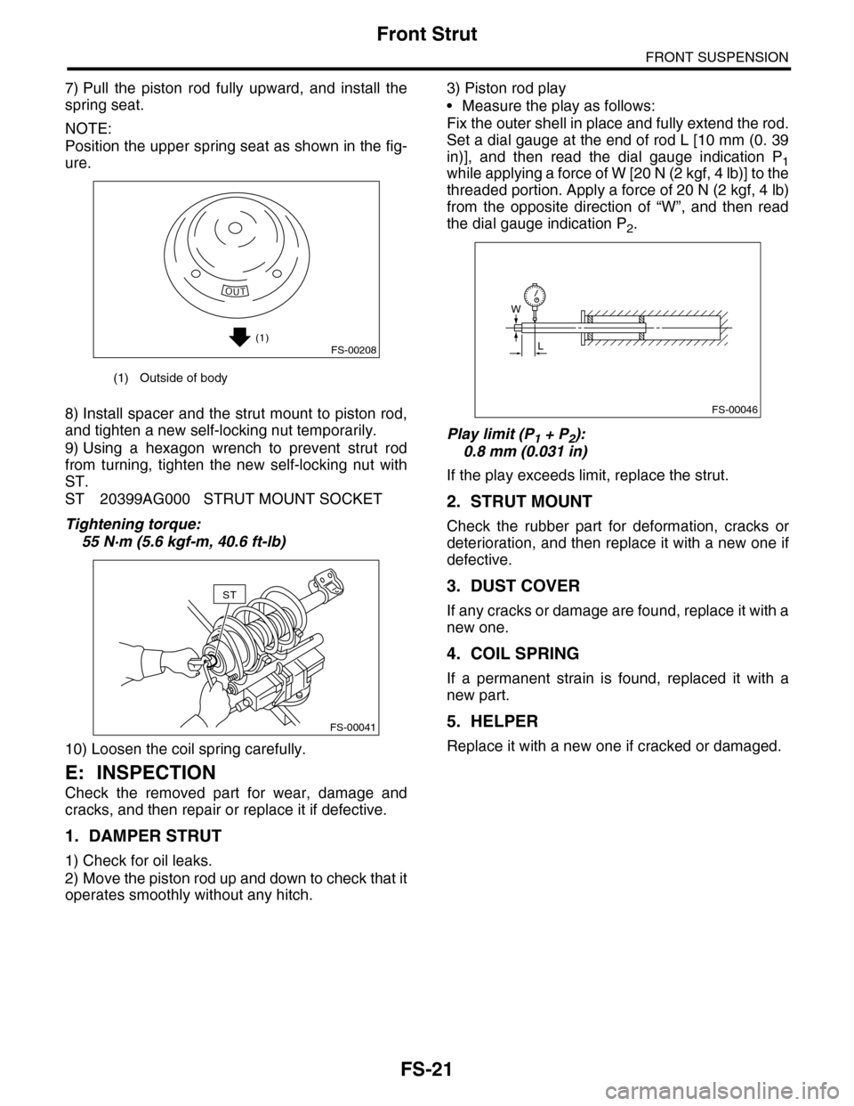
7) Pull the piston rod fully upward, and install the
spring seat.
NOTE:
Position the upper spring seat as shown in the fig-
ure.
8) Install spacer and the strut mount to piston rod,
and tighten a new self-locking nut temporarily.
9) Using a hexagon wrench to prevent strut rod
from turning, tighten the new self-locking nut with
ST.
ST 20399AG000 STRUT MOUNT SOCKET
Tightening torque:
55 N·m (5.6 kgf-m, 40.6 ft-lb)
10) Loosen the coil spring carefully.
E: INSPECTION
Check the removed part for wear, damage and
cracks, and then repair or replace it if defective.
1. DAMPER STRUT
1) Check for oil leaks.
2) Move the piston rod up and down to check that it
operates smoothly without any hitch.
3) Piston rod play
•Measure the play as follows:
Fix the outer shell in place and fully extend the rod.
Set a dial gauge at the end of rod L [10 mm (0. 39
in)], and then read the dial gauge indication P1while applying a force of W [20 N (2 kgf, 4 lb)] to the
threaded portion. Apply a force of 20 N (2 kgf, 4 lb)
from the opposite direction of “W”, and then read
the dial gauge indication P2.
Play limit (P1 + P2):
0.8 mm (0.031 in)
If the play exceeds limit, replace the strut.
2. STRUT MOUNT
Check the rubber part for deformation, cracks or
deterioration, and then replace it with a new one if
defective.
3. DUST COVER
If any cracks or damage are found, replace it with a
new one.
4. COIL SPRING
If a permanent strain is found, replaced it with a
new part.
5. HELPER
Replace it with a new one if cracked or damaged.
(1) Outside of body
(1)FS-00208
FS-00041
ST
FS-00046
W
L
Page 871 of 2453

FS-23
Front Crossmember
FRONT SUSPENSION
8. Front Crossmember
A: REMOVAL
1) Lift-up the vehicle, and then remove the front
wheels.
2) Remove the front exhaust pipe.
3) Remove the front crossmember support plate.
4) Remove the front stabilizer.
5) Disconnect the tie-rod end from housing.
6) Remove the front arm.
7) Remove the nuts attaching the engine mount
cushion rubber to crossmember.
8) Remove the steering universal joint.
9) Disconnect the power steering hose from steer-
ing gearbox.
10) Lift the engine approx. 10 mm (0.39 in) using
the chain block.
11) Support the crossmember with a jack, remove
the bolts securing crossmember to body, and then
gradually lower the crossmember with steering
gearbox as a unit.
CAUTION:
When removing the crossmember downward,
be careful that the tie-rod end does not interfere
with drive shaft boot.
B: INSTALLATION
1) Install in the reverse order of removal.
NOTE:
•Use a new bolt and self-locking nut. For parts
which are not reusable, refer to “COMPONENT”.
•Always tighten the stabilizer bushing in the state
where the vehicle is at curb weight and the wheels
are in full contact with the ground.
Tightening torque:
Crossmember to body:
95 N·m (9.7 kgf-m, 70.1 ft-lb)
Engine mounting to Crossmember:
85 N·m (8.7 kgf-m, 62.7 ft-lb)
Front arm to Crossmember:
95 N·m (9.7 kgf-m, 70.1 ft-lb)
Front arm to Support plate:
145 N·m (14.8 kgf-m, 106.9 ft-lb)
Support plate to Body:
150 N·m (15.3 kgf-m, 110.6 ft-lb)
Tie–rod end to housing:
27.0 N·m (2.75 kgf-m, 19.9 ft-lb)
After tightening to the specified torque, tighten the
castle nut further but within 60° until the hole in the
ball stud is aligned with a slot in castle nut
Universal joint:
24 N·m (2.4 kgf-m, 17.4 ft-lb)
Stabilizer clamp
25 N·m (2.5 kgf-m, 18.1 ft-lb)
Stabilizer link:
60 N·m (6.1 kgf-m, 44.3 ft-lb)
Power steering hose to Steering gearbox:
15 N·m (1.5 kgf-m, 11 ft-lb)
2) Purge air from the power steering system.
3) Inspect the wheel alignment and adjust if neces-
sary.
C: INSPECTION
Check the crossmember for wear, damage or
cracks, and then repair or replace if faulty.
FS-00209
FS-00119
Page 872 of 2453

FS-24
General Diagnostic Table
FRONT SUSPENSION
9. General Diagnostic Table
A: INSPECTION
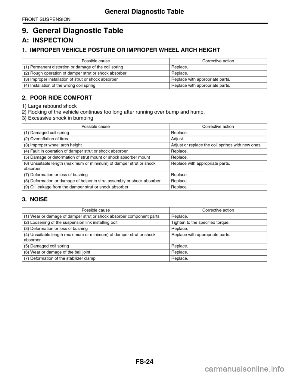
1. IMPROPER VEHICLE POSTURE OR IMPROPER WHEEL ARCH HEIGHT
2. POOR RIDE COMFORT
1) Large rebound shock
2) Rocking of the vehicle continues too long after running over bump and hump.
3) Excessive shock in bumping
3. NOISE
Po ss ibl e c a us e C o r r e ct ive ac ti o n
(1) Permanent distortion or damage of the coil spring Replace.
(2) Rough operation of damper strut or shock absorber Replace.
(3) Improper installation of strut or shock absorber Replace with appropriate parts.
(4) Installation of the wrong coil spring Replace with appropriate parts.
Po ss ibl e ca us e C or r e ct i ve a ct io n
(1) Damaged coil spring Replace.
(2) Overinflation of tires Adjust.
(3) Improper wheel arch height Adjust or replace the coil springs with new ones.
(4) Fault in operation of damper strut or shock absorber Replace.
(5) Damage or deformation of strut mount or shock absorber mount Replace.
(6) Unsuitable length (maximum or minimum) of damper strut or shock
absorber
Replace with appropriate parts.
(7) Deformation or loss of bushing Replace.
(8) Deformation or damage of helper in strut assembly or shock absorber Replace.
(9) Oil leakage from the damper strut or shock absorber Replace.
Po ss ibl e c a us e C o r r e ct ive ac ti o n
(1) Wear or damage of damper strut or shock absorber component parts Replace.
(2) Loosening of the suspension link installing bolt Tighten to the specified torque.
(3) Deformation or loss of bushing Replace.
(4) Unsuitable length (maximum or minimum) of damper strut or shock
absorber
Replace with appropriate parts.
(5) Damaged coil spring Replace.
(6) Wear or damage of the ball joint Replace.
(7) Deformation of the stabilizer clamp Replace.
Page 873 of 2453

PB-2
General Description
PARKING BRAKE
1. General Description
A: SPECIFICATION
B: COMPONENT
1. PARKING BRAKE (REAR DISC BRAKE)
Ty p e M e c h a n i c a l , d r u m i n d i s c r e a r b r a k e s
Effective drum diameter mm (in) 210 (8.27)
Lining dimensions
(Length×Width×Thickness)mm (in)238.2 × 30.0 × 4.0
(9.378 × 1.181 × 0.157)
Clearance adjustment Manual adjustment
Pe da l s t ro ke n o tc he s /N ( k gf, lb ) 5 — 6 / 3 00 ( 30 . 6, 6 7)
(1) Back plate (8) Strut (15) Shoe hold pin
(2) Retainer (9) Primary return spring (16) Self locking nut (with WAX)
(3) Spring washer (10) Secondary return spring
(4) Lever (11) Adjusting springTightening torque: N·m (kgf-m, ft-lb)
(5) Parking brake shoe (Primary) (12) AdjusterT1: 8 (0.8, 5.9)
(6) Parking brake shoe (Secondary) (13) Brake shoe cupT2: 75 (7.6, 55.33)
(7) Strut spring (14) Brake shoe spring
PB-00083
(5)
(14)
(13)
(12)(9)
(11)
(10)
(8)
(7)
(6)
(4)(3)(2)
(1)
(15)
(16)
T1
T2
Page 874 of 2453

PB-3
General Description
PARKING BRAKE
2. PARKING BRAKE CABLE
C: CAUTION
•Wear work clothing, including a cap, protective
goggles and protective shoes during operation.
•Before removal, installation or disassembly, be
sure to clarify the failure. Avoid unnecessary re-
moval, installation, disassembly and replacement.
•Be careful not to burn yourself, because each
part on the vehicle is hot after running.
•Use SUBARU genuine grease etc. or equivalent.
Do not mix grease etc. with that of another grade or
from other manufacturers.
•Be sure to tighten fasteners including bolts and
nuts to the specified torque.
•Place shop jacks or rigid racks at the specified
points.
•Before securing a part in a vise, place cushioning
material such as wood blocks, aluminum plate or
cloth between the part and the vise.
•Make sure grease does not come into contact
with the parking shoes.
(1) Parking brake pedal (6) ClampTightening torque: N·m (kgf-m, ft-lb)
(2) Spacer (7) Rear parking brake cable RHT1: 7.5 (0.76, 5.5)
(3) Adjusting nut (Self-locking nut) (8) Rear parking brake cable LHT2: 8 (0.8, 5.9)
(4) Front parking brake cable (9) Adjuster capT3: 18 (1.8, 13.0)
(5) Bracket T4: 33 (3.4, 24.3)
PB-00084
T3
T4
T3
T3
T3
(5)
(2)
(3)
(6)
(4)(1)
(7)
(9)
(9)
T2
T4
T3
T1
T1
T3
T3
T1
T3
T2
T3
Page 875 of 2453

PB-4
Parking Brake Pedal
PARKING BRAKE
2. Parking Brake Pedal
A: REMOVAL
1) Set the wheel stoppers to tires.
2) Remove the instrument panel lower cover.
er.>
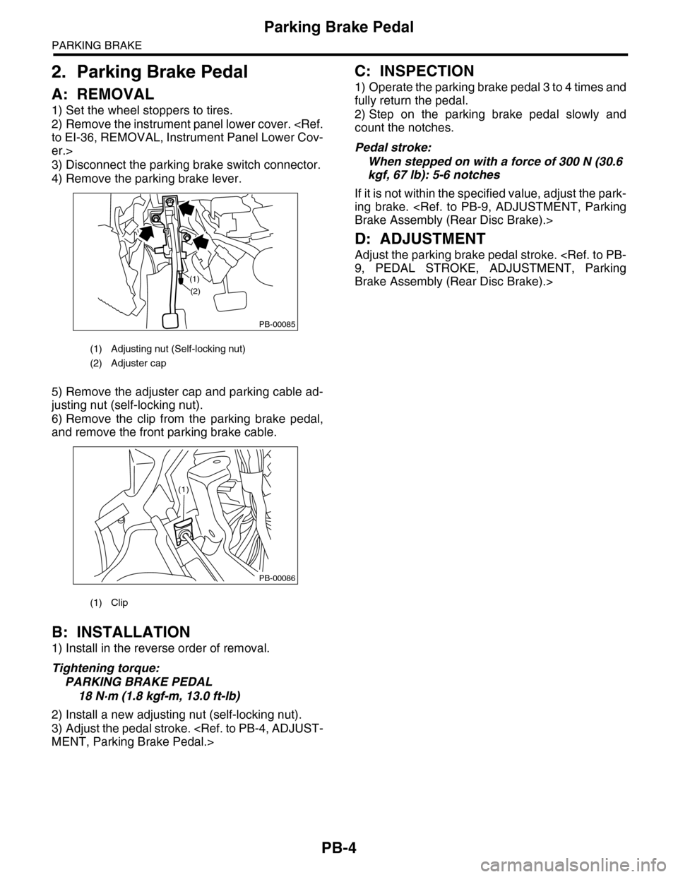
3) Disconnect the parking brake switch connector.
4) Remove the parking brake lever.
5) Remove the adjuster cap and parking cable ad-
justing nut (self-locking nut).
6) Remove the clip from the parking brake pedal,
and remove the front parking brake cable.
B: INSTALLATION
1) Install in the reverse order of removal.
Tightening torque:
PARKING BRAKE PEDAL
18 N·m (1.8 kgf-m, 13.0 ft-lb)
2) Install a new adjusting nut (self-locking nut).
3) Adjust the pedal stroke.
C: INSPECTION
1) Operate the parking brake pedal 3 to 4 times and
fully return the pedal.
2) Step on the parking brake pedal slowly and
count the notches.
Pedal stroke:
When stepped on with a force of 300 N (30.6
kgf, 67 lb): 5-6 notches
If it is not within the specified value, adjust the park-
ing brake.
D: ADJUSTMENT
Adjust the parking brake pedal stroke.
Brake Assembly (Rear Disc Brake).>
(1) Adjusting nut (Self-locking nut)
(2) Adjuster cap
(1) Clip
PB-00085
(1)
(2)
PB-00086
(1)