Page 1113 of 2453

WT-7
Aluminum Wheel
WHEEL AND TIRE SYSTEM
3. Aluminum Wheel
A: REMOVAL
1) Apply the parking brake, and position select le-
ver to “P” or “LOW”.
2) Set the shop jacks or a lift to the specified points,
and support the vehicle with its wheels slightly con-
tacting the floor.
3) Loosen the wheel nuts.
4) Raise the vehicle until its wheels are off the
ground using the jack or a lift.
5) Remove the wheel nuts and wheels.
NOTE:
•When removing the wheels, be careful not to
damage the hub bolts.
•Place the wheels with their outer sides facing up-
ward to prevent wheels from being damaged.
B: INSTALLATION
1) Remove dirt from the mating surface of the
wheel and brake rotor.
2) Attach the wheel to the hub by aligning the wheel
bolt holes with the hub bolts.
3) Temporarily attach the wheel nuts to the hub
bolts. (In the case of aluminum wheels, use SUBA-
RU genuine wheel nuts for aluminum wheels.)
4) Tighten the nuts by hand, making sure the wheel
hub hole is aligned correctly to the guide portion of
hub.
5) Tighten the wheel nuts in a diagonal selection to
the specified torque. Use a wheel nut wrench.
Wheel nut tightening torque:
110 N·m (11.2 kgf-m, 81.1 ft-lb)
CAUTION:
•Tighten the wheel nuts in two or three steps
by gradually increasing the torque on opposing
nuts, until they reach the specified torque.
•Do not push the wrench by foot. Always use
both hands when tightening the nuts.
•Make sure the bolt, nut and the nut seating
surface of the wheel are free from oil.
6) If a wheel is removed for replacement or for re-
pair of a puncture, retighten the wheel nuts to the
specified torque after driving 1,000 km (600 miles).
C: INSPECTION
1) Deformation or damage to the rim may cause air
leakage. Check the rim flange for deformation,
cracks or damage, and repair or replace as neces-
sary.
2) Jack-up the vehicle until wheels clear the floor.
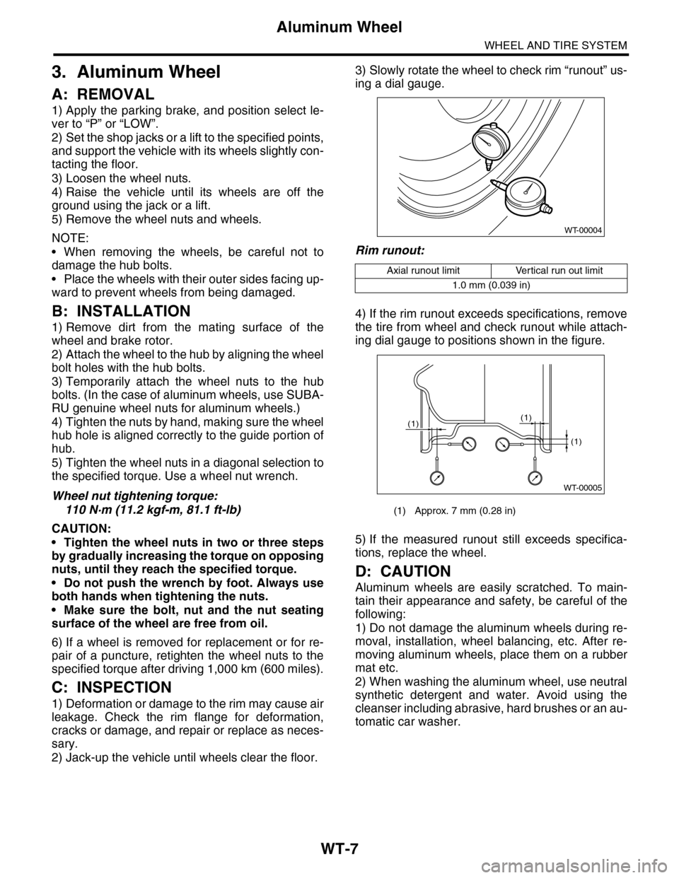
3) Slowly rotate the wheel to check rim “runout” us-
ing a dial gauge.
Rim runout:
4) If the rim runout exceeds specifications, remove
the tire from wheel and check runout while attach-
ing dial gauge to positions shown in the figure.
5) If the measured runout still exceeds specifica-
tions, replace the wheel.
D: CAUTION
Aluminum wheels are easily scratched. To main-
tain their appearance and safety, be careful of the
following:
1) Do not damage the aluminum wheels during re-
moval, installation, wheel balancing, etc. After re-
moving aluminum wheels, place them on a rubber
mat etc.
2) When washing the aluminum wheel, use neutral
synthetic detergent and water. Avoid using the
cleanser including abrasive, hard brushes or an au-
tomatic car washer.
Axial runout limit Vertical run out limit
1.0 mm (0.039 in)
(1) Approx. 7 mm (0.28 in)
WT-00004
WT-00005
(1)
(1)
(1)
Page 1117 of 2453

WT-11
Tire Pressure Monitoring System
WHEEL AND TIRE SYSTEM
6. Tire Pressure Monitoring
System
A: REMOVAL
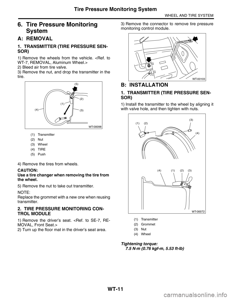
1. TRANSMITTER (TIRE PRESSURE SEN-
SOR)
1) Remove the wheels from the vehicle.
WT-7, REMOVAL, Aluminum Wheel.>
2) Bleed air from tire valve.
3) Remove the nut, and drop the transmitter in the
tire.
4) Remove the tires from wheels.
CAUTION:
Use a tire changer when removing the tire from
the wheel.
5) Remove the nut to take out transmitter.
NOTE:
Replace the grommet with a new one when reusing
transmitter.
2. TIRE PRESSURE MONITORING CON-
TROL MODULE
1) Remove the driver’s seat.
MOVAL, Front Seat.>
2) Turn up the floor mat in the driver’s seat area.
3) Remove the connector to remove tire pressure
monitoring control module.
B: INSTALLATION
1. TRANSMITTER (TIRE PRESSURE SEN-
SOR)
1) Install the transmitter to the wheel by aligning it
with valve hole, and then tighten with nuts.
Tightening torque:
7.5 N·m (0.76 kgf-m, 5.53 ft-lb)
(1) Transmitter
(2) Nut
(3) Wheel
(4) TIRE
(5) Push
(1)
(4)
(5)
(2)
WT-00098
(3)
(1) Transmitter
(2) Grommet
(3) Nut
(4) Wheel
WT-00103
WT-00072
(2)(3)
(4)
(1)
(3)(2)(1)(4)
Page 1118 of 2453
WT-12
Tire Pressure Monitoring System
WHEEL AND TIRE SYSTEM
2) Install the tires to wheels.
CAUTION:
•Use a tire changer when installing tire to
wheel.
•To prevent damaging the transmitter, set the
tire changer boom in the position as shown in
the figure.
3) Install the wheels to vehicle.
STALLATION, Aluminum Wheel.>
4) Register the transmitter ID to the tire pressure
monitoring control module.
REGISTER TRANSMITTER ID, OPERATION,
Subaru Select Monitor.>
2. TIRE PRESSURE MONITORING CON-
TROL MODULE
Install in the reverse order of removal.
Tightening torque:
8 N·m (0.8 kgf-m, 5.8 ft-lb)
C: ADJUSTMENT
Re-register the transmitter ID when transmitter has
been replaced or tires have been rotated.
TPM(diag)-9, REGISTER TRANSMITTER ID, OP-
ERATION, Subaru Select Monitor.>
(1) Transmitter
(2) Turn table rotation direction
(3) 90°
(4) Tire changer boom
Page 1119 of 2453
WT-13
Spare Tire Hoist
WHEEL AND TIRE SYSTEM
7. Spare Tire Hoist
A: REMOVAL
1) Remove the spare tire from the vehicle.
2) Lift-up the vehicle.
3) Remove the spare tire guide.
B: INSTALLATION
Install in the reverse order of removal.
Tightening torque:
33 N·m (3.7 kgf-m, 24.3 ft-lb)
C: DISASSEMBLY
Remove the spare tire hoist.
D: ASSEMBLY
Assemble in the reverse order of disassembly.
Tightening torque:
33 N·m (3.7 kgf-m, 24.3 ft-lb)
WT-00105
Page 1123 of 2453
CO(H6DO)-4
General Description
COOLING
B: COMPONENT
1. WATER PUMP
(1) Water pump ASSY (4) GasketTightening torque: N·m (kgf-m, ft-lb)
(2) O-ring (5) Thermostat coverT: 6.4 (0.65, 4.7)
(3) Thermostat
(1)
(2)
(4)
(5)
T
T
CO-02125
(3)
Page 1124 of 2453
CO(H6DO)-5
General Description
COOLING
2. RADIATOR AND RADIATOR FAN
(1) Radiator lower cushion (11) Radiator hose B (20) Over flow hose
(2) Engine coolant drain cock (12) Radiator hose D (21) Engine coolant reservoir tank
(3) Radiator (13) Radiator sub fan
(4) Radiator upper cushion (14) Radiator fan shroudTightening torque: N·m (kgf-m, ft-lb)
(5) Radiator upper bracket (15) Radiator fan control unitT1: 3.8 (0.39, 2.8)
(6) Clamp (16) Radiator sub fan motorT2: 2.6 (0.27, 1.9)
(7) Radiator hose A (17) Radiator main fan motorT3: 6.3 (0.64, 4.6)
(8) Radiator hose B (18) Radiator main fanT4: 7.5 (0.76, 5.5)
(9) Radiator cap (19) Engine coolant reservoir tank capT5: 12 (1.2, 8.9)
(10) Radiator hose bracket
CO-02191
T4
T4
T4
T2
T1
T3
T5(7)
(6)
(13)
(18)
(14)
(16)
(17)
(15)
(21)
(19)
(20)
(9)
(10)
(6)
(11)
(6)
(1)
(3)
(2)
(12)
(6)
(8)
(4)
(5)
(6)(6)
Page 1125 of 2453

CO(H6DO)-6
General Description
COOLING
C: CAUTION
•Wear work clothing, including a cap, protective goggles and protective shoes during operation.
•Remove contamination including dirt and corrosion before removal, installation or disassembly.
•Keep the disassembled parts in order and protect them from dust and dirt.
•Before removal, installation or disassembly, be sure to clarify the failure. Avoid unnecessary removal, in-
stallation, disassembly and replacement.
•Be careful not to burn yourself, because each part on the vehicle is hot after running.
•Be sure to tighten fasteners including bolts and nuts to the specified torque.
•Place shop jacks or rigid racks at the specified points.
•Before disconnecting connectors of sensors or units, be sure to disconnect the ground cable from battery.
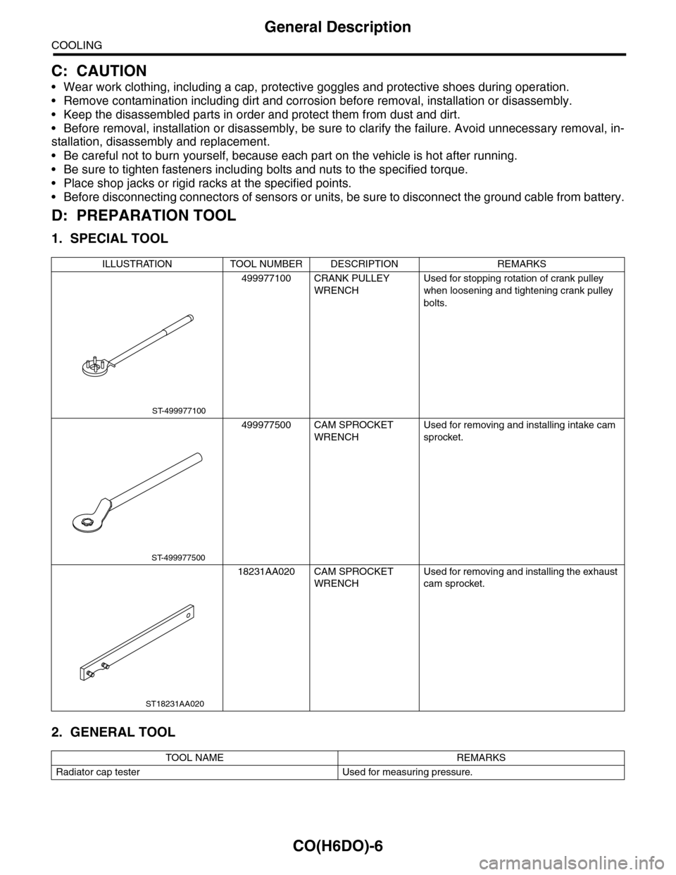
D: PREPARATION TOOL
1. SPECIAL TOOL
2. GENERAL TOOL
ILLUSTRATION TOOL NUMBER DESCRIPTION REMARKS
499977100 CRANK PULLEY
WRENCH
Used for stopping rotation of crank pulley
when loosening and tightening crank pulley
bolts.
499977500 CAM SPROCKET
WRENCH
Used for removing and installing intake cam
sprocket.
18231AA020 CAM SPROCKET
WRENCH
Used for removing and installing the exhaust
cam sprocket.
TOOL NAME REMARKS
Radiator cap tester Used for measuring pressure.
ST-499977100
ST-499977500
ST18231AA020
Page 1132 of 2453

CO(H6DO)-13
Water Pump
COOLING
4. Water Pump
A: REMOVAL
1) Remove the radiator.
REMOVAL, Radiator.>
2) Remove the V-belts.
3) Remove the front chain cover.
Cover.>
4) Remove the timing chain assembly.
Assembly.>
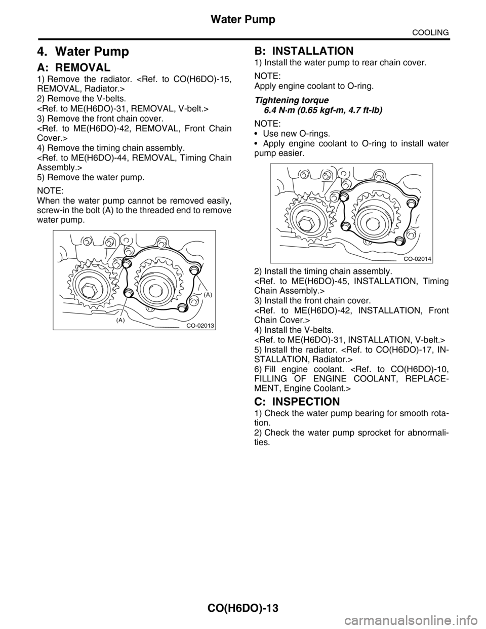
5) Remove the water pump.
NOTE:
When the water pump cannot be removed easily,
screw-in the bolt (A) to the threaded end to remove
water pump.
B: INSTALLATION
1) Install the water pump to rear chain cover.
NOTE:
Apply engine coolant to O-ring.
Tightening torque
6.4 N·m (0.65 kgf-m, 4.7 ft-lb)
NOTE:
•Use new O-rings.
•Apply engine coolant to O-ring to install water
pump easier.
2) Install the timing chain assembly.
Chain Assembly.>
3) Install the front chain cover.
Chain Cover.>
4) Install the V-belts.
5) Install the radiator.
STALLATION, Radiator.>
6) Fill engine coolant.
FILLING OF ENGINE COOLANT, REPLACE-
MENT, Engine Coolant.>
C: INSPECTION
1) Check the water pump bearing for smooth rota-
tion.
2) Check the water pump sprocket for abnormali-
ties.
CO-02013
(A)
(A)
CO-02014