2009 SUBARU TRIBECA torque
[x] Cancel search: torquePage 1190 of 2453
![SUBARU TRIBECA 2009 1.G Service Workshop Manual EN(H6DO)(diag)-29
Subaru Select Monitor
ENGINE (DIAGNOSTICS)
5. READ CURRENT DATA FOR ENGINE (OBD MODE)
1) On the «Main Menu» display screen, select the {Each System Check} and press the [YES] key.
SUBARU TRIBECA 2009 1.G Service Workshop Manual EN(H6DO)(diag)-29
Subaru Select Monitor
ENGINE (DIAGNOSTICS)
5. READ CURRENT DATA FOR ENGINE (OBD MODE)
1) On the «Main Menu» display screen, select the {Each System Check} and press the [YES] key.](/manual-img/17/7322/w960_7322-1189.png)
EN(H6DO)(diag)-29
Subaru Select Monitor
ENGINE (DIAGNOSTICS)
5. READ CURRENT DATA FOR ENGINE (OBD MODE)
1) On the «Main Menu» display screen, select the {Each System Check} and press the [YES] key.
2) On the «System Selection Menu» display screen, select the {Engine} and press the [YES] key.
3) Press the [YES] key after the information of engine type has been displayed.
4) On the «Engine Diagnosis» display screen, select the {OBD System} and press the [YES] key.
5) On the «OBD Menu» display screen, select the {Current Data Display/Save}, and then press the [YES]
key.
6) On the «Data Display Menu» screen, select the {Data Display} and press the [YES] key.
7) Using the scroll key, scroll the display screen up or down until the desired data is shown.
•A list of the support data is shown in the following table.
AT c o o r d i n a t e f u e l c u t d e m a n d s i g n a l AT c o o r d i n a t e f u e l c u t d e m a n d — O F F
Ve h i c l e d y n a m i c s c o n t r o l ( V D C ) t o r q u e d o w n
prohibition outputBan of Torque Down — Permission
Ve h i c l e d y n a m i c s c o n t r o l ( V D C ) t o r q u e d o w n
demandVDC torque down demand — OFF
AT c o o r d i n a t e p e r m i s s i o n s i g n a l AT c o o r d i n a t e p e r m i s s i o n s i g n a l — P e r m i s s i o n
Electronic throttle control motor relay signal ETC motor relay — ON
Stop light switch signal Stop Light Switch — OFF
SET/COAST switch signal SET/COAST SW — OFF
RESUME/ACCEL switch signal RESUME/ACCEL SW — OFF
Brake switch signal Brake SW — OFF
Main switch signal Main SW — OFF
Body integrated unit data reception Body Int. Unit Data — Yes
Body integlated unit counter update Body Int. Unit Count — Yes
Cruise control cancel switch signal CC Cancel SW — OFF
Va r i a b l e v a l v e l i f t d i a g n o s i s o i l p r e s s u r e sw i t c h
signal 1Oil Temperature SW1 — ON
Va r i a b l e v a l v e l i f t d i a g n o s i s o i l p r e s s u r e sw i t c h
signal 2Oil Temperature SW2 — ON
Description Display Unit of measure
Number of diagnosis code Number of Diag. Codes: 0
Condition of malfunction indicator light MI (MIL) ON or OFF
Monitoring test of misfire Misfire monitoring Finish
Monitoring test of fuel system Fuel system monitoring Finish
Monitoring test of comprehensive component Component monitoring Finish
Te s t o f c a t a l y s t C a t a l y s t D i a g n o s i s F i n i s h o r i n c o m p l e t e
Te s t o f h e a t i n g - t y p e c a t a l y s t H e a t e d c a t a l y s t N o
Te s t o f e v a p o r a t i v e e m i s s i o n p u r g e c o n t r o l s y s t e m E v a p o r a t i v e p u r g e s y s t e m F i n i s h o r i n c o m p l e t e
Te s t o f s e c o n d a r y a i r s y s t e m S e c o n d a r y a i r s y s t e m N o
Te s t o f a i r c o n d i t i o n i n g s y s t e m r e f r i g e r a n t A / C s y s t e m r e f r i g e r a n t N o
Te s t o f o x y g e n s e n s o r O x y g e n s e n o r F i n i s h o r i n c o m p l e t e
Te s t o f o x y g e n s e n s o r h e a t e r O x y g e n s e n s o r h e a t e r F i n i s h
Te s t o f E G R s y s t e m E G R s y s t e m N o s u p p o r t
A/F control #1 Fuel system for Bank 1 OPEN early period
A/F control #2 Fuel system for Bank 2 OPEN early period
Calculated load valve Calculated load valve %
Engine coolant temperature Coolant Temp. °C
A/F compensation #1 Short term fuel trim B1 %
A/F learning #1 Long term fuel trim B1 %
A/F compensation #2 Short term fuel trim #2 %
A/F learning #2 Long term fuel trim B2 %
Description Display Unit of measure Note (at idling)
Page 1193 of 2453
![SUBARU TRIBECA 2009 1.G Service Workshop Manual EN(H6DO)(diag)-32
Subaru Select Monitor
ENGINE (DIAGNOSTICS)
7. LED OPERATION MODE FOR ENGINE
1) On the «Main Menu» display screen, select the {Each System Check} and press the [YES] key.
2) On the SUBARU TRIBECA 2009 1.G Service Workshop Manual EN(H6DO)(diag)-32
Subaru Select Monitor
ENGINE (DIAGNOSTICS)
7. LED OPERATION MODE FOR ENGINE
1) On the «Main Menu» display screen, select the {Each System Check} and press the [YES] key.
2) On the](/manual-img/17/7322/w960_7322-1192.png)
EN(H6DO)(diag)-32
Subaru Select Monitor
ENGINE (DIAGNOSTICS)
7. LED OPERATION MODE FOR ENGINE
1) On the «Main Menu» display screen, select the {Each System Check} and press the [YES] key.
2) On the «System Selection Menu» display screen, select the {Engine} and press the [YES] key.
3) Press the [YES] key after the information of engine type has been displayed.
4) On the «Engine Diagnosis» display screen, select the {Current Data Display/Save}, and then press the
[YES] key.
5) On the «Data Display» screen, select the {Data LED Display} and press the [YES] key.
6) Using the scroll key, scroll the display screen up or down until the desired data is shown.
•A list of the support data is shown in the following table.
NOTE:
For detailed operation procedure, refer to the “SUBARU SELECT MONITOR OPERATION MANUAL”.
Description Display Message When LED “ON” required
Te s t m o d e s i g n a l Te s t m o d e t e r m i n a l D c h e c k / U c h e c k D c h e c k
Neutral position switch signal Neutral SW Neutral/Other than neutral Neutral
Idle switch signal Soft idle SW Idle/Other than idle In idle
Ignition switch signal Ignition SW ON Input/OFF Input ON input
Pow er s te e r in g sw it c h s ig n al Pow er s te e r in g S W ON I np u t/ O FF I np u t ON i np ut
Air conditioning switch signal A/C SW ON Input/OFF Input ON input
Starter switch signal Starter SW ON Input/OFF Input ON input
Fr o nt ox yg e n mo n it o r 1 Ft O 2 mo n it o r 1 Le a n/ Ri ch Ric h
Fr o nt ox yg e n mo n it o r 2 Ft O 2 mo n it o r 2 Le a n/ Ri ch Ric h
Knocking signal Knock signal Yes/No Yes
Crankshaft position sensor signal Crankshaft angle signal Yes/No Yes
Camshaft position sensor signal Camshaft angle signal Yes/No Yes
Rear defogger switch signal Rear defogger SW ON Input/OFF Input ON input
Blower fan switch signal Blower fan SW ON Input/OFF Input ON input
Light switch signal Light SW ON Input/OFF Input ON input
Wiper switch signal Wiper SW ON Input/OFF Input ON input
A/C middle pressure switch signal A/C middle pressure SW ON Input/OFF Input ON input
Air conditioner compressor relay sig-
nalCompressor relay ON output/OFF output ON output
Drain valve signal Vent. Solenoid Valve ON or OFF When drain valve is ON.
AT r e t a r d a n g l e d e m a n d s i g n a l AT r e t a r d a n g l e d e m a n d Ye s / N o Ye s
AT f u e l c u t s i g n a l AT f u e l c u t Ye s / N o Ye s
VDC torque down prohibition output Torque down output ON/OFF Prohibition
VDC torque down demand Torque down demand Yes/No Yes
AT c o o r d i n a t e p e r m i s s i o n s i g n a lAT c o o r d i n a t e p e r m i s s i o n
signalON/OFF Permission
Electronic throttle control motor relay
signalETC motor relay ON/OFF ON
Stop light switch signal Stop SW ON Input/OFF Input ON input
SET/COAST switch signal SET/CST SW ON Input/OFF Input ON input
RESUME/ACCEL switch signal RES/ACC SW ON Input/OFF Input ON input
Brake switch signal Brake SW ON Input/OFF Input ON input
Main switch signal Main SW ON Input/OFF Input ON input
Body integrated unit data reception Body Int. Unit Data Yes/No Yes
Body integrated unit counter update Body Int. Unit Count Yes/No Yes
Cruise control cancel switch signal CC Cancel SW ON Input/OFF Input ON input
Va r i a b l e va l v e l i f t d i a g n o s i s o i l p r e s -
sure switch signal 1Oil Temperature SW1 ON/OFF ON
Va r i a b l e va l v e l i f t d i a g n o s i s o i l p r e s -
sure switch signal 2Oil Temperature SW2 ON/OFF ON
Page 1553 of 2453
EN(H6DO)(diag)-392
General Diagnostic Table
ENGINE (DIAGNOSTICS)
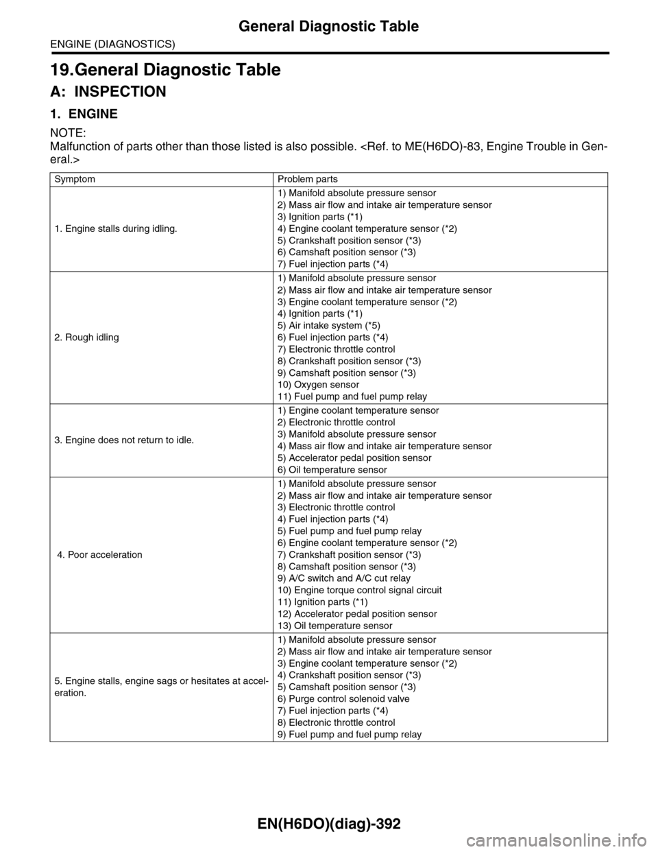
19.General Diagnostic Table
A: INSPECTION
1. ENGINE
NOTE:
Malfunction of parts other than those listed is also possible.
Symptom Problem parts
1. Engine stalls during idling.
1) Manifold absolute pressure sensor
2) Mass air flow and intake air temperature sensor
3) Ignition parts (*1)
4) Engine coolant temperature sensor (*2)
5) Crankshaft position sensor (*3)
6) Camshaft position sensor (*3)
7) Fuel injection parts (*4)
2. Rough idling
1) Manifold absolute pressure sensor
2) Mass air flow and intake air temperature sensor
3) Engine coolant temperature sensor (*2)
4) Ignition parts (*1)
5) Air intake system (*5)
6) Fuel injection parts (*4)
7) Electronic throttle control
8) Crankshaft position sensor (*3)
9) Camshaft position sensor (*3)
10) Oxygen sensor
11) Fuel pump and fuel pump relay
3. Engine does not return to idle.
1) Engine coolant temperature sensor
2) Electronic throttle control
3) Manifold absolute pressure sensor
4) Mass air flow and intake air temperature sensor
5) Accelerator pedal position sensor
6) Oil temperature sensor
4. Poor acceleration
1) Manifold absolute pressure sensor
2) Mass air flow and intake air temperature sensor
3) Electronic throttle control
4) Fuel injection parts (*4)
5) Fuel pump and fuel pump relay
6) Engine coolant temperature sensor (*2)
7) Crankshaft position sensor (*3)
8) Camshaft position sensor (*3)
9) A/C switch and A/C cut relay
10) Engine torque control signal circuit
11) Ignition parts (*1)
12) Accelerator pedal position sensor
13) Oil temperature sensor
5. Engine stalls, engine sags or hesitates at accel-
eration.
1) Manifold absolute pressure sensor
2) Mass air flow and intake air temperature sensor
3) Engine coolant temperature sensor (*2)
4) Crankshaft position sensor (*3)
5) Camshaft position sensor (*3)
6) Purge control solenoid valve
7) Fuel injection parts (*4)
8) Electronic throttle control
9) Fuel pump and fuel pump relay
Page 1557 of 2453
EX(H6DO)-3
General Description
EXHAUST
B: CAUTION
•Wear work clothing, including a cap, protective
goggles and protective shoes during operation.
•Remove contamination including dirt and corro-
sion before removal, installation or disassembly.
•Keep the disassembled parts in order and pro-
tect them from dust and dirt.
•Before removal, installation or disassembly, be
sure to clarify the failure. Avoid unnecessary re-
moval, installation, disassembly and replacement.
•Be careful not to burn yourself, because each
part on the vehicle is hot after running.
•Be sure to tighten fasteners including bolts and
nuts to the specified torque.
•Place shop jacks or rigid racks at the specified
points.
•Before disconnecting connectors of sensors or
units, be sure to disconnect the ground cable from
battery.
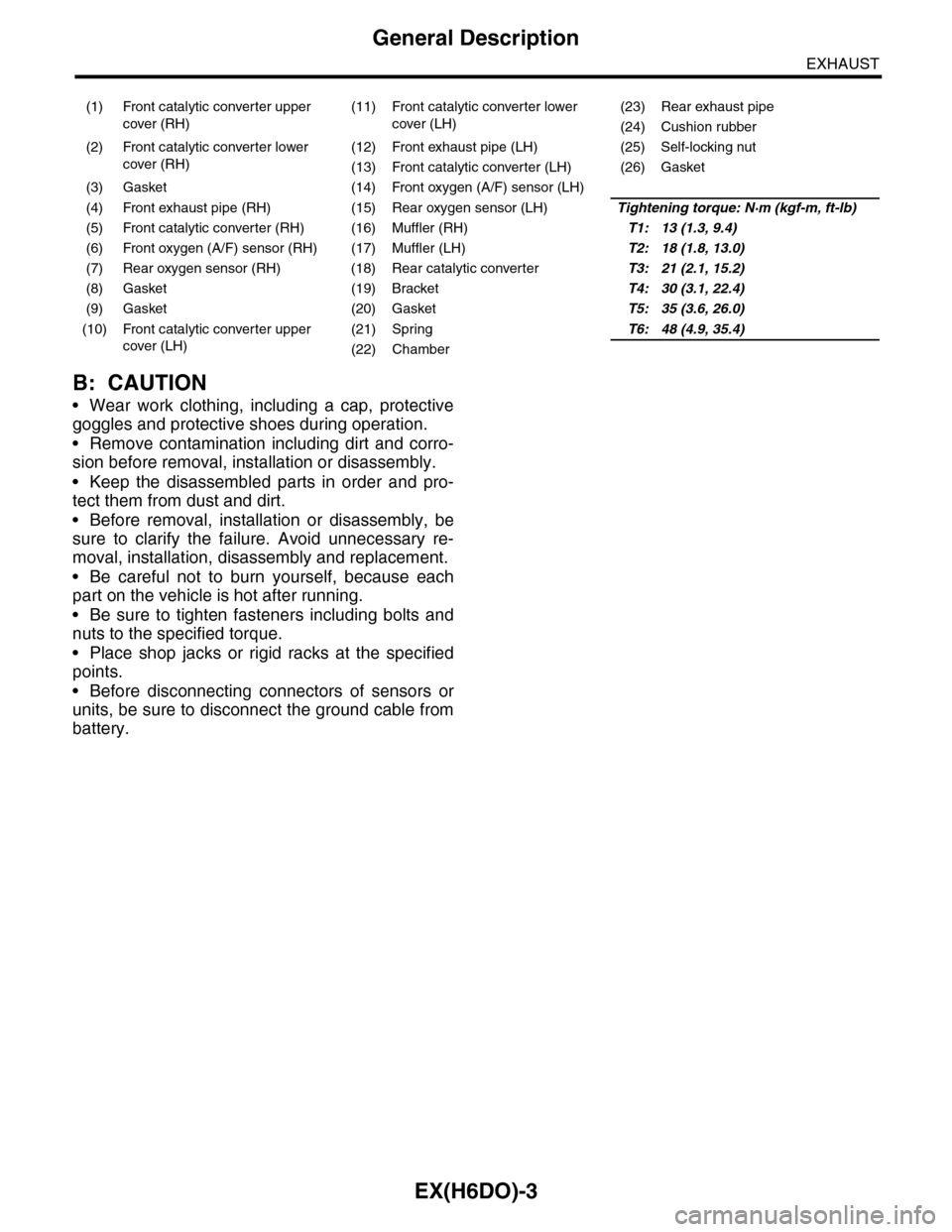
(1) Front catalytic converter upper
cover (RH)
(11) Front catalytic converter lower
cover (LH)
(23) Rear exhaust pipe
(24) Cushion rubber
(2) Front catalytic converter lower
cover (RH)
(12) Front exhaust pipe (LH) (25) Self-locking nut
(13) Front catalytic converter (LH) (26) Gasket
(3) Gasket (14) Front oxygen (A/F) sensor (LH)
(4) Front exhaust pipe (RH) (15) Rear oxygen sensor (LH)Tightening torque: N·m (kgf-m, ft-lb)
(5) Front catalytic converter (RH) (16) Muffler (RH)T1: 13 (1.3, 9.4)
(6) Front oxygen (A/F) sensor (RH) (17) Muffler (LH)T2: 18 (1.8, 13.0)
(7) Rear oxygen sensor (RH) (18) Rear catalytic converterT3: 21 (2.1, 15.2)
(8) Gasket (19) BracketT4: 30 (3.1, 22.4)
(9) Gasket (20) GasketT5: 35 (3.6, 26.0)
(10) Front catalytic converter upper
cover (LH)
(21) SpringT6: 48 (4.9, 35.4)
(22) Chamber
Page 1559 of 2453
EX(H6DO)-5
Front Exhaust Pipe
EXHAUST
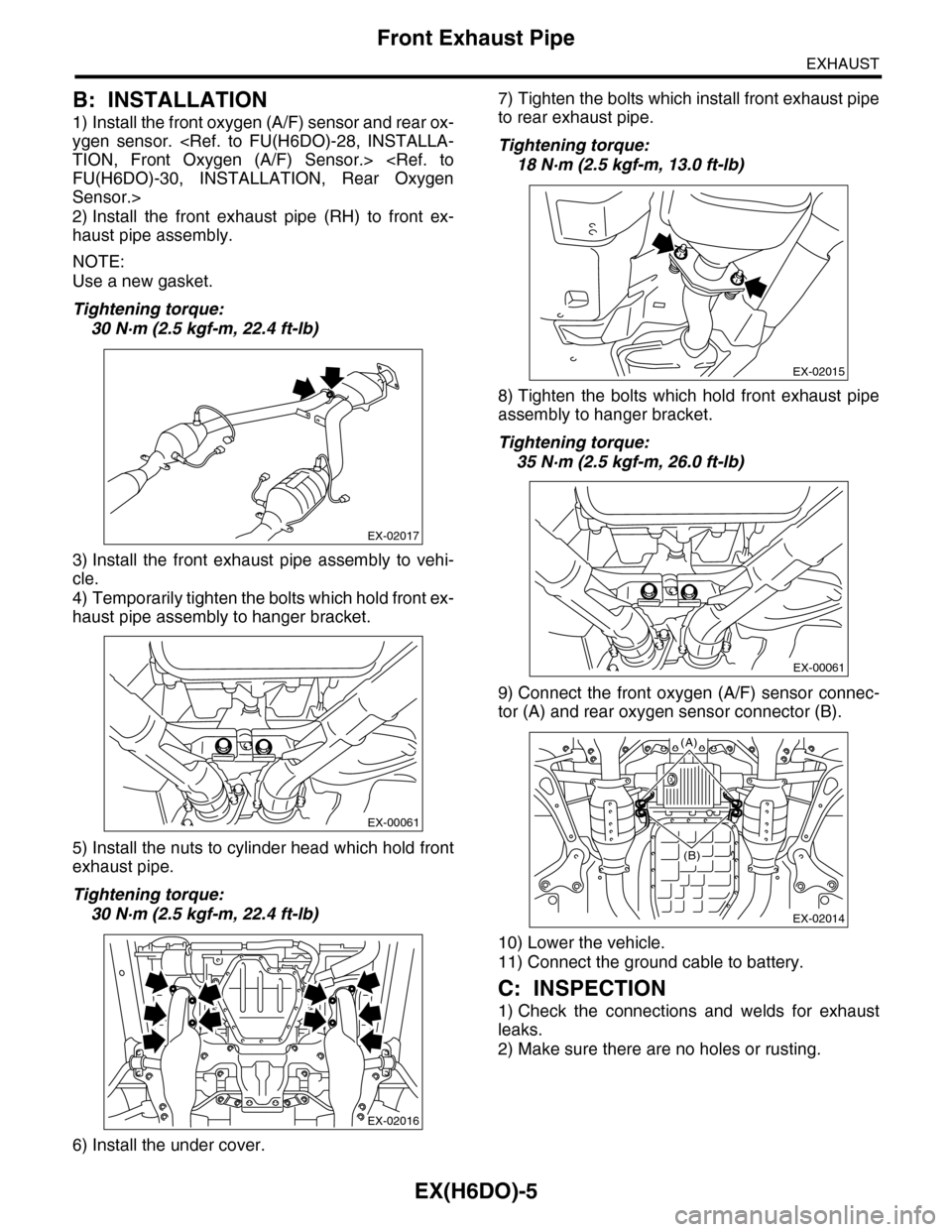
B: INSTALLATION
1) Install the front oxygen (A/F) sensor and rear ox-
ygen sensor.
Sensor.>
2) Install the front exhaust pipe (RH) to front ex-
haust pipe assembly.
NOTE:
Use a new gasket.
Tightening torque:
30 N·m (2.5 kgf-m, 22.4 ft-lb)
3) Install the front exhaust pipe assembly to vehi-
cle.
4) Temporarily tighten the bolts which hold front ex-
haust pipe assembly to hanger bracket.
5) Install the nuts to cylinder head which hold front
exhaust pipe.
Tightening torque:
30 N·m (2.5 kgf-m, 22.4 ft-lb)
6) Install the under cover.
7) Tighten the bolts which install front exhaust pipe
to rear exhaust pipe.
Tightening torque:
18 N·m (2.5 kgf-m, 13.0 ft-lb)
8) Tighten the bolts which hold front exhaust pipe
assembly to hanger bracket.
Tightening torque:
35 N·m (2.5 kgf-m, 26.0 ft-lb)
9) Connect the front oxygen (A/F) sensor connec-
tor (A) and rear oxygen sensor connector (B).
10) Lower the vehicle.
11) Connect the ground cable to battery.
C: INSPECTION
1) Check the connections and welds for exhaust
leaks.
2) Make sure there are no holes or rusting.
EX-02017
EX-00061
EX-02016
EX-02015
EX-00061
EX-02014
(A)
(B)
Page 1561 of 2453
EX(H6DO)-7
Rear Exhaust Pipe
EXHAUST
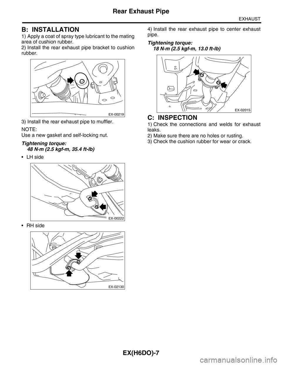
B: INSTALLATION
1) Apply a coat of spray type lubricant to the mating
area of cushion rubber.
2) Install the rear exhaust pipe bracket to cushion
rubber.
3) Install the rear exhaust pipe to muffler.
NOTE:
Use a new gasket and self-locking nut.
Tightening torque:
48 N·m (2.5 kgf-m, 35.4 ft-lb)
•LH side
•RH side
4) Install the rear exhaust pipe to center exhaust
pipe.
Tightening torque:
18 N·m (2.5 kgf-m, 13.0 ft-lb)
C: INSPECTION
1) Check the connections and welds for exhaust
leaks.
2) Make sure there are no holes or rusting.
3) Check the cushion rubber for wear or crack.
EX-00219
EX-00222
EX-02130
EX-02015
Page 1562 of 2453
EX(H6DO)-8
Muffler
EXHAUST
4. Muffler
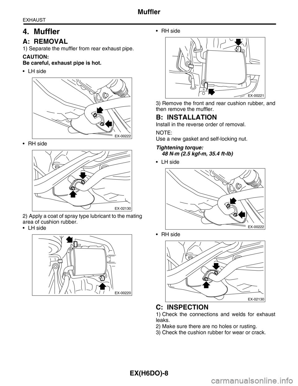
A: REMOVAL
1) Separate the muffler from rear exhaust pipe.
CAUTION:
Be careful, exhaust pipe is hot.
•LH side
•RH side
2) Apply a coat of spray type lubricant to the mating
area of cushion rubber.
•LH side
•RH side
3) Remove the front and rear cushion rubber, and
then remove the muffler.
B: INSTALLATION
Install in the reverse order of removal.
NOTE:
Use a new gasket and self-locking nut.
Tightening torque:
48 N·m (2.5 kgf-m, 35.4 ft-lb)
•LH side
•RH side
C: INSPECTION
1) Check the connections and welds for exhaust
leaks.
2) Make sure there are no holes or rusting.
3) Check the cushion rubber for wear or crack.
EX-00222
EX-02130
EX-00220
EX-00221
EX-00222
EX-02130
Page 1565 of 2453
FU(H6DO)-4
General Description
FUEL INJECTION (FUEL SYSTEMS)
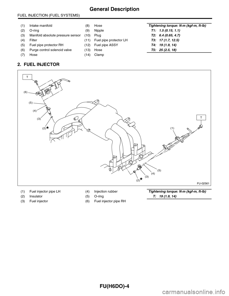
2. FUEL INJECTOR
(1) Intake manifold (8) HoseTightening torque: N·m (kgf-m, ft-lb)
(2) O-ring (9) NippleT1: 1.5 (0.15, 1.1)
(3) Manifold absolute pressure sensor (10) PlugT2: 6.4 (0.65, 4.7)
(4) Filter (11) Fuel pipe protector LHT3: 17 (1.7, 12.5)
(5) Fuel pipe protector RH (12) Fuel pipe ASSYT4: 19 (1.9, 14)
(6) Purge control solenoid valve (13) HoseT5: 25 (2.5, 18)
(7) Hose (14) Clamp
(1) Fuel injector pipe LH (4) Injection rubberTightening torque: N·m (kgf-m, ft-lb)
(2) Insulator (5) O-ringT: 19 (1.9, 14)
(3) Fuel injector (6) Fuel injector pipe RH
FU-02561
(6)
T
T
(5)
(4)
(3)
(2)
(2)(3)(4)(5)
(1)