2009 SUBARU TRIBECA Combination meter
[x] Cancel search: Combination meterPage 179 of 2453

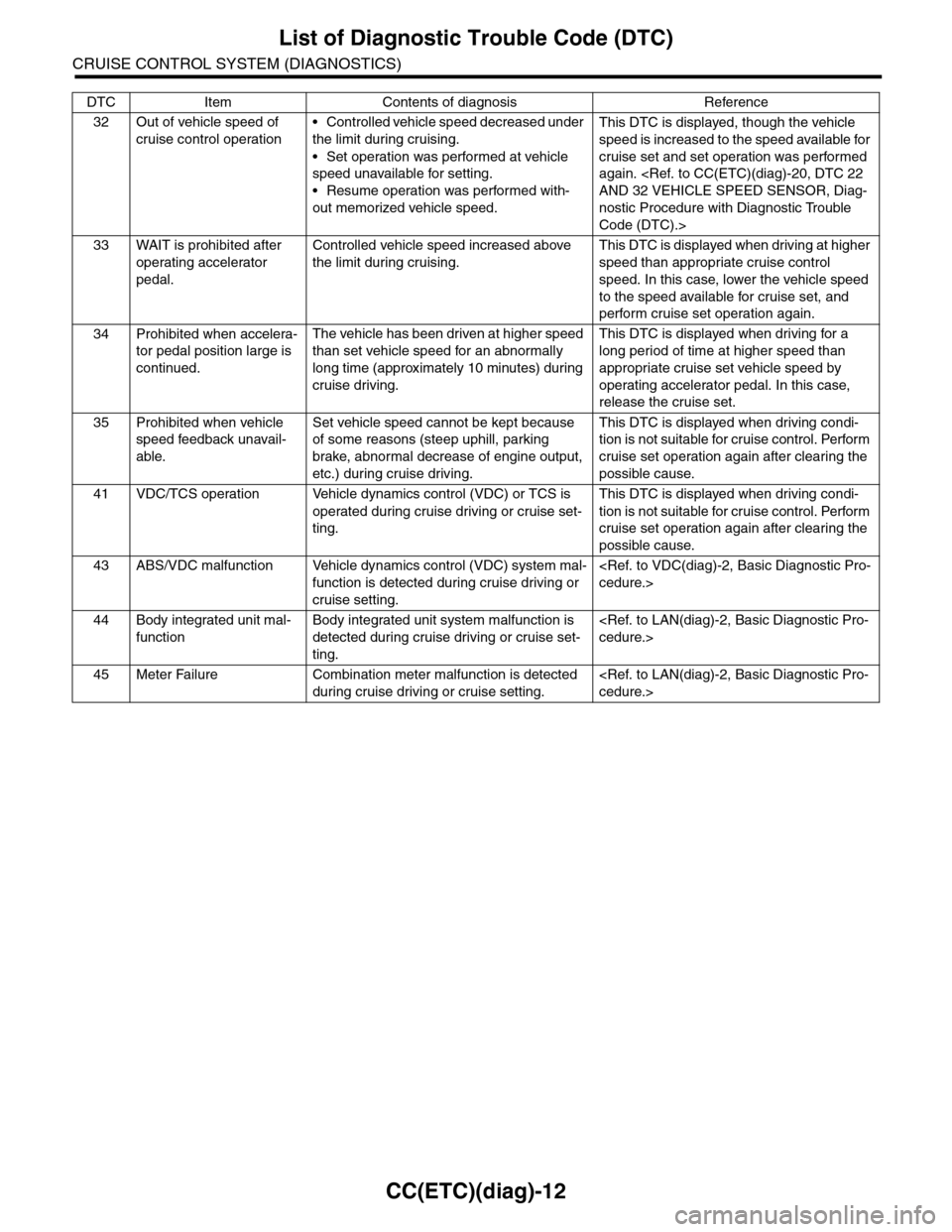
CC(ETC)(diag)-12
List of Diagnostic Trouble Code (DTC)
CRUISE CONTROL SYSTEM (DIAGNOSTICS)
32 Out of vehicle speed of
cruise control operation
•Controlled vehicle speed decreased under
the limit during cruising.
•Set operation was performed at vehicle
speed unavailable for setting.
•Resume operation was performed with-
out memorized vehicle speed.
This DTC is displayed, though the vehicle
speed is increased to the speed available for
cruise set and set operation was performed
again.
nostic Procedure with Diagnostic Trouble
Code (DTC).>
33 WAIT is prohibited after
operating accelerator
pedal.
Controlled vehicle speed increased above
the limit during cruising.
This DTC is displayed when driving at higher
speed than appropriate cruise control
speed. In this case, lower the vehicle speed
to the speed available for cruise set, and
perform cruise set operation again.
34 Prohibited when accelera-
tor pedal position large is
continued.
The vehicle has been driven at higher speed
than set vehicle speed for an abnormally
long time (approximately 10 minutes) during
cruise driving.
This DTC is displayed when driving for a
long period of time at higher speed than
appropriate cruise set vehicle speed by
operating accelerator pedal. In this case,
release the cruise set.
35 Prohibited when vehicle
speed feedback unavail-
able.
Set vehicle speed cannot be kept because
of some reasons (steep uphill, parking
brake, abnormal decrease of engine output,
etc.) during cruise driving.
This DTC is displayed when driving condi-
tion is not suitable for cruise control. Perform
cruise set operation again after clearing the
possible cause.
41 VDC/TCS operation Vehicle dynamics control (VDC) or TCS is
operated during cruise driving or cruise set-
ting.
This DTC is displayed when driving condi-
tion is not suitable for cruise control. Perform
cruise set operation again after clearing the
possible cause.
43 ABS/VDC malfunction Vehicle dynamics control (VDC) system mal-
function is detected during cruise driving or
cruise setting.
44 Body integrated unit mal-
function
Body integrated unit system malfunction is
detected during cruise driving or cruise set-
ting.
45 Meter Failure Combination meter malfunction is detected
during cruise driving or cruise setting.
DTC Item Contents of diagnosis Reference
Page 187 of 2453

CC(ETC)(diag)-20
Diagnostic Procedure with Diagnostic Trouble Code (DTC)
CRUISE CONTROL SYSTEM (DIAGNOSTICS)
E: DTC 22 AND 32 VEHICLE SPEED SENSOR
DIAGNOSIS:
Open or short circuit in vehicle speed sensor system.
TROUBLE SYMPTOM:
Cruise control cannot be set. (Cancelled immediately.)
Step Check Yes No
1 CHECK IGNITION SWITCH CIRCUIT
1) Turn the ignition switch to OFF.
2) Disconnect the ECM harness connector.
3) Turn the ignition switch to ON.
4) Measure the voltage between harness con-
nector terminal and chassis ground.
Connector & terminal
(B135) No. 19 (+) — Chassis ground (–):
Is the voltage more than 10 V? Check poor con-
tact of ECM con-
nector.
•Check fuse No.
12 (in fuse & relay
box).
•Check the har-
ness for open or
short circuit
between ignition
switch and ECM.
Step Check Yes No
1CHECK ABS WARNING LIGHT.
1) Turn the ignition switch to ON.
2) After the initial operation of combination
meter is completed, check if the VDC warning
light continues to illuminate.
Does the VDC warning light
continue to illuminate?
Check the
VDCCM.
Basic Diagnostic
Procedure.>
Go to step 2.
2CHECK LAN COMMUNICATION CIRCUIT
ERROR DISPLAY
Check if the communication error is displayed
on the odo/trip meter in combination meter.
Is the error code «Er xx» dis-
played on odo/trip meter?
Check the LAN
communication cir-
cuit.
Diagnostic Proce-
dure.>
Replace the ECM.
Engine Control
Module (ECM).>
Page 210 of 2453

ET-25
GPS Antenna
ENTERTAINMENT
20.GPS Antenna
A: REMOVAL
1) Disconnect the ground cable from battery.
2) Remove the combination meter.
3) Remove the audio.
4) Remove the navigation display.
5) Remove the screw to remove the GPS bracket.
6) Remove the GPS antenna cord connector from
the steering support beam stay (on the driver’s
side).
B: INSTALLATION
Install in the reverse order of removal.
ET-00187
Page 282 of 2453

EI-40
Instrument Panel Assembly
EXTERIOR/INTERIOR TRIM
17.Instrument Panel Assembly
A: REMOVAL
CAUTION:
Take care of the following when removing the
instrument panel from the vehicle body.
•Refer to “CAUTION” of “General Description”
before starting the work.
•Be sure to disconnect each harness connec-
tor. Applying excessive pulling force may dam-
age the harness.
•Be careful to the harness of airbag system.
Damage of the harness may cause the air bag
system malfunction.
•Take care not to damage the interior trims
when removing the instrument panel from the
vehicle body.
NOTE:
•Putting alignment marks to each connector as
necessary facilitates the reassembly work.
•When storing the removed instrument panel, be
sure to prepare a table or the like to put the instru-
ment panel on in order to prevent damage.
1. INSTRUMENT PANEL UPPER
1) Disconnect the ground cable from battery and
wait for at least 20 seconds before starting work.
2) Remove the console box.
3) Remove the instrument panel lower cover.
er.>
4) Remove the glove box.
5) Remove the center console.
6) Remove the audio unit.
7) Remove the combination meter assembly.
8) Remove the upper grille.
9) Remove the multi function display or navigation
monitor, and warning box.
10) Remove the front pillar upper trim.
11) Remove the mounting bolts of the passenger’s
side air bag module.
12) Remove the following screws.
•In combination meter house
•At the sides (left and right) of instrument panel
•Instrument panel center
EI-01327
EI-01328
EI-01330
EI-01329
Page 409 of 2453

AC(diag)-32
Diagnostic Procedure for Sensors
HVAC SYSTEM (AUTO A/C) (DIAGNOSTICS)
Step Check Yes No
1CHECK AMBIENT SENSOR.
1) Turn the ignition switch to OFF.
2) Disconnect the connector from ambient
sensor.
3) Measure the resistance between connector
terminals of ambient sensor.
Te r m i n a l s
No. 1 — No. 2:
Is the resistance approximately
1.7 kΩ at 25°C (77°F)?
Go to step 2.Replace the ambi-
ent sensor.
2CHECK INPUT SIGNAL FOR AMBIENT SEN-
SOR.
1) Turn the ignition to ON.
2) Measure the voltage between connector
(F78) terminals.
Connector & terminal
(F78) No. 1 (+) — No. 2 (–):
Is the voltage approx. 5 V? Go to step 6.Go to step 3.
3CHECK OUTPUT SIGNAL OF BODY INTE-
GRATED UNIT.
1) Turn the ignition switch to OFF.
2) Draw out the body integrated unit.
3) Disconnect the connector from ambient
sensor.
4) Turn the ignition switch to ON.
5) Measure the voltage between connector
terminals of body integrated unit.
Connector & terminal
(B281) No. 3 (+) — No. 10 (–):
Is the voltage approx. 5 V? Go to step 4.Go to step 6.
4CHECK HARNESS CONNECTOR BETWEEN
BODY INTEGRATED UNIT AND AMBIENT
SENSOR.
1) Turn the ignition switch to OFF.
2) Disconnect the connector from body inte-
grated unit.
3) Measure the resistance of harness
between body integrated unit and ambient sen-
sor.
Connector & terminal
(F78) No. 1 — (B281) No. 10:
Is the resistance less than 1
Ω?
Go to step 5.Repair the open
circuit of harness
between body inte-
grated unit and
ambient sensor.
5CHECK HARNESS CONNECTOR BETWEEN
BODY INTEGRATED UNIT AND AMBIENT
SENSOR.
Measure the resistance of harness between
body integrated unit and ambient sensor.
Connector & terminal
(F78) No. 2 — (B281) No. 3:
Is the resistance less than 1
Ω?
Go to step 6.Repair the open
circuit of harness
between body inte-
grated unit and
ambient sensor.
6CHECK COMMUNICATION ERROR DIS-
PLAY.
1) Connect the connectors of body integrated
unit and ambient sensor as originally con-
nected.
2) Check if “Er xx” is displayed on the Odo/Trip
meter in combination meter after turning the
ignition switch to ON.
Is “Er xx” displayed? Check the commu-
nication circuit.
Diagnostic Proce-
dure.>
Go to step 7.
7CHECK POOR CONTACT.
Check poor contact of auto A/C control module
connector.
Is there poor contact in con-
nector?
Repair the con-
nector.
Replace the auto
A/C control mod-
ule.
Control Unit (Auto
A/C Model).>
Page 430 of 2453

IM (diag)-14
List of Diagnostic Trouble Code (DTC)
IMMOBILIZER (DIAGNOSTICS)
9. List of Diagnostic Trouble Code (DTC)
A: LIST
1. ECM
NOTE:
Perform the diagnosis of engine DTC when the DTC except for immobilizer DTC is detected.
DTC Item Contents of diagnosis Index No.
P0513 Incorrect Immobilizer Key Incorrect immobilizer key (Use of
unregistered key in body integrated
unit)
cedure with Diagnostic Trouble Code
(DTC).>
P1570 ANTENNA Faulty antenna
nostic Trouble Code (DTC).>
P1571 Reference Code Incompatibility Reference code incompatibility
between body integrated unit and
ECM
tic Procedure with Diagnostic Trouble Code
(DTC).>
P1572 EGI — Immobilizer Communi-
cation
(Except Antenna Circuit)
Communication failure between
body integrated unit and ECM
CUIT), Diagnostic Procedure with Diagnostic
Tr o u b l e C o d e ( D T C ) . >
P1574 Key — Immobilizer Communica-
tion
Fai l ur e o f b o dy i n te gra t ed u n it to ve r -
ify key (transponder) ID code
Procedure with Diagnostic Trouble Code
(DTC).>
P1576 EGI Control Module EEPROM ECM malfunctioning
cedure with Diagnostic Trouble Code
(DTC).>
P1577 IMM Control Module EEPROM Body integrated unit malfunctioning
cedure with Diagnostic Trouble Code
(DTC).>
P1578 Meter malfunctioning Reference code incompatibility
between body integrated unit and
combination meter
nostic Trouble Code (DTC).>
Page 431 of 2453

IM (diag)-15
List of Diagnostic Trouble Code (DTC)
IMMOBILIZER (DIAGNOSTICS)
2. BODY INTEGRATED UNIT
NOTE:
In immobilizer system, performing the starter relay control. When the body integrated unit detect the incon-
formity of reference code, immediately out put the starter relay cut signal to ECM, and then ECM stop the
starter relay operation. In this case, engine does not start, and DTC is not recorded in ECM. Check that the
engine does not start on the DTC of body integrated unit.
DTC Item Contents of diagnosis Index No.Relation between
ECM and DTC
B0401 M collation
NG
Reference code incompati-
bility between body inte-
grated unit and combination
meter
Code (DTC).>
P1578
B0402 Immobilizer
Key collation
NG
•Incorrect immobilizer key
(Use of unregistered key in
body integrated unit)
•Faulty antenna
Diagnostic Trouble Code (DTC).>
with Diagnostic Trouble Code (DTC).>or
FA I L U R E , D i a g n o s t i c P r o c e d u r e w i t h D i a g n o s t i c
Tr o u b l e C o d e ( D T C ) . >
•P0513
•P1570
•P1574
B0403 E/G request
NG
Communication failure
between body integrated
unit and ECM
tic Procedure with Diagnostic Trouble Code (DTC).>
P1572
Page 440 of 2453

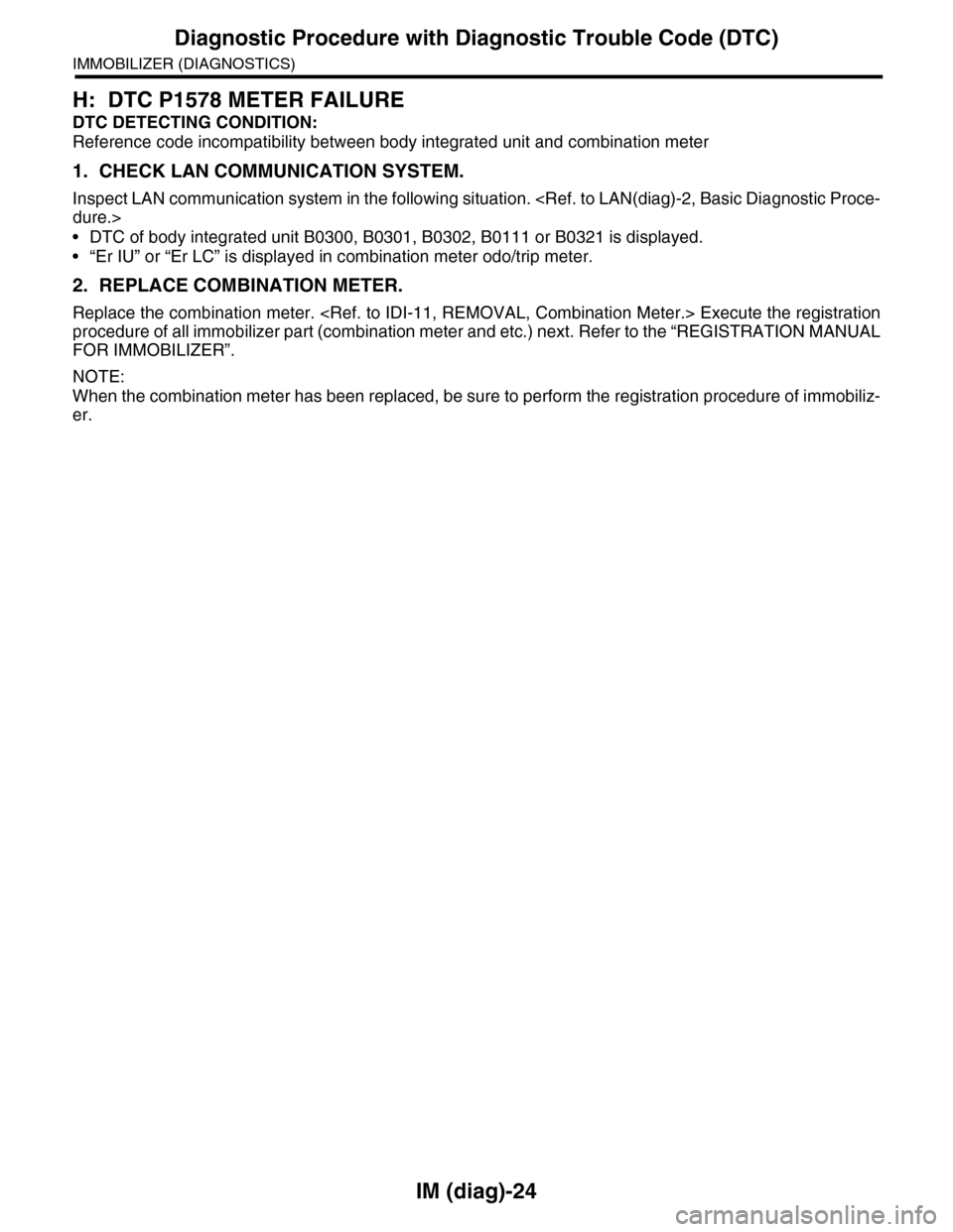
IM (diag)-24
Diagnostic Procedure with Diagnostic Trouble Code (DTC)
IMMOBILIZER (DIAGNOSTICS)
H: DTC P1578 METER FAILURE
DTC DETECTING CONDITION:
Reference code incompatibility between body integrated unit and combination meter
1. CHECK LAN COMMUNICATION SYSTEM.
Inspect LAN communication system in the following situation.
•DTC of body integrated unit B0300, B0301, B0302, B0111 or B0321 is displayed.
•“Er IU” or “Er LC” is displayed in combination meter odo/trip meter.
2. REPLACE COMBINATION METER.
Replace the combination meter.
procedure of all immobilizer part (combination meter and etc.) next. Refer to the “REGISTRATION MANUAL
FOR IMMOBILIZER”.
NOTE:
When the combination meter has been replaced, be sure to perform the registration procedure of immobiliz-
er.