Page 748 of 2453

BR-34
Brake Hose
BRAKE
B: INSTALLATION
1. FRONT BRAKE HOSE
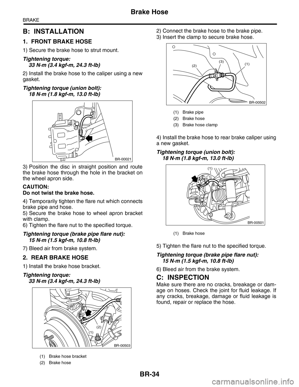
1) Secure the brake hose to strut mount.
Tightening torque:
33 N·m (3.4 kgf-m, 24.3 ft-lb)
2) Install the brake hose to the caliper using a new
gasket.
Tightening torque (union bolt):
18 N·m (1.8 kgf-m, 13.0 ft-lb)
3) Position the disc in straight position and route
the brake hose through the hole in the bracket on
the wheel apron side.
CAUTION:
Do not twist the brake hose.
4) Temporarily tighten the flare nut which connects
brake pipe and hose.
5) Secure the brake hose to wheel apron bracket
with clamp.
6) Tighten the flare nut to the specified torque.
Tightening torque (brake pipe flare nut):
15 N·m (1.5 kgf-m, 10.8 ft-lb)
7) Bleed air from brake system.
2. REAR BRAKE HOSE
1) Install the brake hose bracket.
Tightening torque:
33 N·m (3.4 kgf-m, 24.3 ft-lb)
2) Connect the brake hose to the brake pipe.
3) Insert the clamp to secure brake hose.
4) Install the brake hose to rear brake caliper using
a new gasket.
Tightening torque (union bolt):
18 N·m (1.8 kgf-m, 13.0 ft-lb)
5) Tighten the flare nut to the specified torque.
Tightening torque (brake pipe flare nut):
15 N·m (1.5 kgf-m, 10.8 ft-lb)
6) Bleed air from the brake system.
C: INSPECTION
Make sure there are no cracks, breakage or dam-
age on hoses. Check the joint for fluid leakage. If
any cracks, breakage, damage or fluid leakage is
found, repair or replace the hose.
(1) Brake hose bracket
(2) Brake hose
BR-00021
BR-00503
(1)
(2)
(1) Brake pipe
(2) Brake hose
(3) Brake hose clamp
(1) Brake hose
BR-00502
(1)(2)(3)
BR-00501
(1)
Page 749 of 2453

BR-35
Brake Pipe
BRAKE
13.Brake Pipe
A: REMOVAL
NOTE:
The airbag system wiring harness is routed near
the center brake pipe.
CAUTION:
•All airbag system wiring harness and con-
nectors are colored yellow. Do not use electri-
cal test equipment on these circuits.
•Be careful not to damage the airbag system
wiring harness when servicing the center brake
pipe.
•When removing the brake pipe, do not bend.
B: INSTALLATION
NOTE:
The airbag system wiring harness is routed near
the center brake pipe.
CAUTION:
•All airbag system wiring harness and con-
nectors are colored yellow. Do not use electri-
cal test equipment on these circuits.
•Be careful not to damage the airbag system
wiring harness when servicing the center brake
pipe.
•When installing the brake pipe, do not bend.
•After installing the brake pipe and hose, per-
form air bleed.
•After installing the brake hoses, make sure
that they do not contact the tires or suspension
assembly, etc.
Brake pipe tightening torque:
15 N·m (1.5 kgf-m, 10.8 ft-lb)
C: INSPECTION
Make sure there are no cracks, breakage or dam-
age on hoses. Check the joint for fluid leakage. If
any cracks, breakage, damage or fluid leakage is
found, repair or replace the pipes.
NOTE:
Use a mirror when inspecting back sides and other
locations which are hard to see.
Page 751 of 2453

BR-37
Stop Light Switch
BRAKE
15.Stop Light Switch
A: REMOVAL
1) Disconnect the ground cable from the battery.
2) Disconnect the stop light switch connector.
3) Loosen the nuts, unscrew the stop light switch,
and remove stop light switch.
B: INSTALLATION
1) Install the stop light switch onto the bracket with
screws and position it with the nut.
2) Adjust the stop light switch position, and then
tighten the nut.
Switch.>
Tightening torque:
8 N·m (0.8 kgf-m, 5.8 ft-lb)
C: INSPECTION
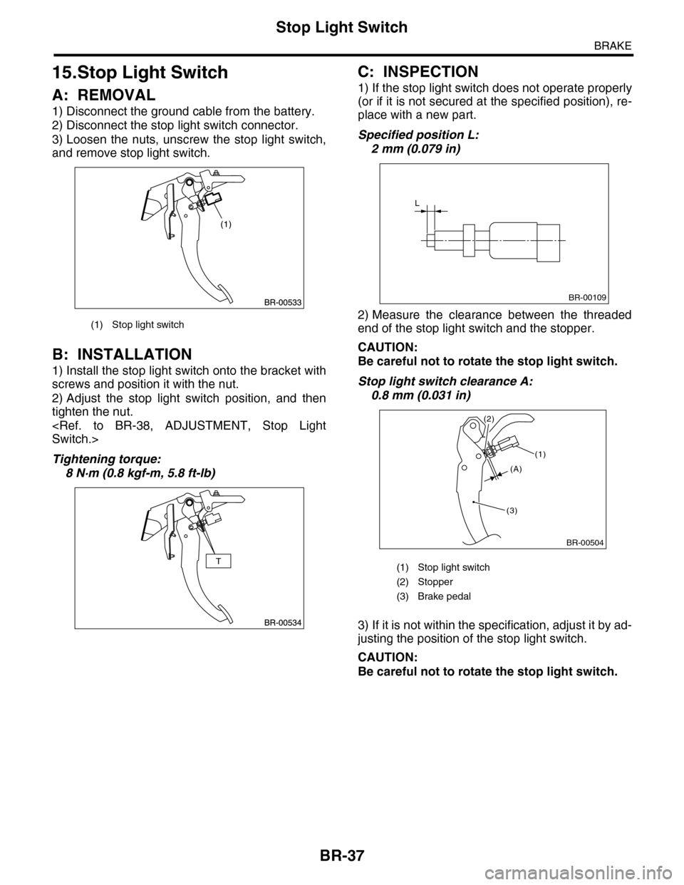
1) If the stop light switch does not operate properly
(or if it is not secured at the specified position), re-
place with a new part.
Specified position L:
2 mm (0.079 in)
2) Measure the clearance between the threaded
end of the stop light switch and the stopper.
CAUTION:
Be careful not to rotate the stop light switch.
Stop light switch clearance A:
0.8 mm (0.031 in)
3) If it is not within the specification, adjust it by ad-
justing the position of the stop light switch.
CAUTION:
Be careful not to rotate the stop light switch.
(1) Stop light switch
(1) Stop light switch
(2) Stopper
(3) Brake pedal
L
BR-00109
BR-00504
(1)
(3)
(2)
(A)
Page 752 of 2453
BR-38
Stop Light Switch
BRAKE
D: ADJUSTMENT
Loosen the lock nut, and adjust the stop light switch
position until the clearance between the threaded
end of the stop light switch and stopper (A) be-
comes 0. 8 mm (0. 031 in). Then, tighten the lock
nut.
Tightening torque:
8 N·m (0.8 kgf-m, 5.8 ft-lb)
NOTE:
Tighten lock nut B until the threaded end of switch
contacts the stopper. Hold the switch so that it does
not rotate, and loosen the lock nut B approx. 60°.
The clearance (A) will become 0.3 mm (0.012 in).
(1) Stop light switch
(2) Lock nut A
(3) Lock nut B
(4) Stopper
(5) Brake pedal
BR-00505
(1)
(5)
(4)
(A)(3)
(2)
Page 753 of 2453

BR-39
Brake Vacuum Pump
BRAKE
16.Brake Vacuum Pump
A: REMOVAL
1. BRAKE VACUUM PUMP
1) Disconnect the ground cable from the battery.
2) Disconnect the brake vacuum pump connector.
3) Remove the vacuum hose.
4) Remove the bolt, and remove the brake vacuum
pump.
2. VACUUM HOSE
Remove the clip and remove the vacuum hose.
B: INSTALLATION
1. BRAKE VACUUM PUMP
Install in the reverse order of removal.
Tightening torque:
7.5 N·m (0.76 kgf-m, 5.5 ft-lb)
2. VACUUM HOSE
Install in the reverse order of removal.
CAUTION:
The vacuum hose has an installation direction.
Make sure to install in the proper direction.
C: INSPECTION
1. BRAKE VACUUM PUMP
Inspect for whether or not the pump operates when
battery voltage is applied to the connector terminal.
2. VACUUM HOSE
Check to see that air only flows in one direction,
when air is blown into or sucked from the hose.
(1) To engine
(2) Vacuum hose
(3) Vacuum pipe
(4) Marking (Marking to vacuum pipe side)
BR-00506
BR-00507
(1)
(2)(2)
(4)
(3)
ENG
Page 754 of 2453
BR-40
Brake Vacuum Sensor
BRAKE
17.Brake Vacuum Sensor
A: REMOVAL
1) Disconnect the ground cable from the battery.
2) Disconnect the brake vacuum sensor connector.
3) Remove the vacuum hose from the brake vacu-
um sensor.
4) Remove the bolt, and remove the brake vacuum
sensor.
B: INSTALLATION
Install in the reverse order of removal.
Tightening torque:
7.5 N·m (0.76 kgf-m, 5.5 ft-lb)
BR-00509
Page 755 of 2453

BR-41
General Diagnostic Table
BRAKE
18.General Diagnostic Table
A: INSPECTION
Trouble and possible causeCorrective action
1. Insufficient braking
performance
(1) Fluid leakage from the hydraulic mechanism Correct or replace. (cup, piston seal, piston
boot, master cylinder piston kit, pipe or
hose)
(2) Entry of air into the hydraulic mechanism Bleed air.
(3) Wear, deteriorated surface material, water or fluid on
lining
Replace, grind or clean.
(4) Improper operation of master cylinder, disc caliper,
brake booster or check valve
Correct or replace.
2. Unstable or uneven
braking
(1) Fluid on lining or rotor Correct the cause of fluid leakage, and
clean or replace.
(2) Rotor defective Repair or replace the rotor.
(3) Improper lining contact, deteriorated surface, deterio-
rated or wear lining material
Repair by grinding, or replace.
(4) Deformed back plate Repair or replace.
(5) Over inflation of tires Adjust air pressure.
(6) Defective wheel alignment Adjust alignment.
(7) Loose back plate or suppor t installation bolt Tighten to the specified torque.
(8) Faulty wheel bearing Replace.
(9) Defective hydraulic system Replace the cylinder, brake pipe or hose.
(10) Unstable effect of parking brake Check, adjust or replace the rear brake and
cable system.
3. Excessive pedal
stroke
(1) Entry of air into the hydraulic mechanism Bleed air.
(2) Excessive play in the master cylinder push rod Adjust.
(3) Fluid leakage from the hydraulic mechanism Correct or replace. (cup, piston seal, piston
boot, master cylinder piston kit, pipe or
hose)
(4) Improper lining contact or worn lining Correct or replace.
4. Brake dragging or
improper brake
return
(1) Insufficient pedal play Adjust play.
(2) Improper master cylinder return Clean or replace the cylinder.
(3) Clogged hydraulic system Replace.
(4) Improper return or adjustment of parking brake Repair or adjust.
(5) Weakened spring tension or breakage of shoe return
spring
Replace the spring.
(6) Improper disc caliper operation Correct or replace.
(7) Faulty wheel bearing Replace.
Brake noise (1)
(creaking sound)
(1) Hardened or deteriorated brake pad Replace the pad.
(2) Worn brake pad Replace the pad.
(3) Loose back plate or suppor t installation bolt Tighten to the specified torque.
(4) Loose wheel bearing Tighten to the specified torque.
(5) Dir ty rotor Clean the rotor, or clean and replace brake
assembly.
6. Brake noise (2)
(hissing sound)
(1) Worn brake pad Replace the pad.
(2) Improperly installed pad Correct or replace the pad.
(3) Loose or bent rotor Retighten or replace.
7. Brake noise (3)
(click sound)
Excessively worn pad or suppor t Replace the pad or the suppor t.
Page 786 of 2453

DI-2
General Description
DIFFERENTIALS
1. General Description
A: SPECIFICATION
1. REAR DIFFERENTIAL
When replacing a rear differential assembly, select the correct one according to the following table.
NOTE:
•Using a different rear differential assembly will cause the drive train and tires to drag or emit abnormal
noise.
•For option code, refer to “ID” section.
2. IDENTIFICATION
Identification label positions are shown in the fol-
lowing figures. For details concerning identification,
refer to the “ID” section.
3. REAR DIFFERENTIAL GEAR OIL
Recommended gear oil:
GL–5 (75W–90)
NOTE:
Each oil manufacturer has its base oil and addi-
tives. Thus, do not mix two or more brands.
4. SERVICE DATA
Rear differential type VA2-type
Identification XX
LSD type—
Ty p e o f g e a r H y p o i d g e a r
Gear ratio (Number of gear teeth) 3.583 (43/12)
Oil capacity 0.82 (0.8 US qt, 0.7 lmp qt)
Rear differential gear oil GL-5
(1) Identification
ID-00114
(1)
(1) Item
(2) Rear differential gear oil
(3) API classification
(4) SAE viscosity No. and applicable temperature
MT-00001
(1)
(4)GL-5(3)
(2)
( C)( F)-30 -26 -15 15
9085W80W75W -90
25 30 -5 0-22-1523328659775
Drive pinion bearing preload Measure with spring measurement. (Mea-
sured from the companion flange bolt)
N (kgf, lb)
12.7 — 32.2 (1.3 — 3.28, 2.9 — 7.24)
Measure with torque wrench
N·m (kgf–m, ft–lb)0.48 — 1.22 (0.045 — 0.124, 0.32 — 0.9)
Hypoid driven gear to drive pinion backlash mm (in) 0.10 — 0.15 (0.0039 — 0.0059)