Page 699 of 2453
WW-4
General Description
WIPER AND WASHER SYSTEMS
3. WASHER TANK
C: CAUTION
•Connect the connectors and hoses securely during reassembly.
•After reassembly, make sure functional parts operate smoothly.
•Be careful with the airbag system wire harness which passes near electrical parts and switches.
•All airbag system wiring harness and connectors are colored yellow. Do not use a tester equipment on
these circuits.
•Care must be taken when connecting the hoses to pipes so that there are no bends or blockage.
•If even a small amount of silicon oil or grease enters tank and washer fluid passages, an oil film will be
formed on the glass and will cause the wiper to chatter and judder. Make sure that no oil comes into contact
with the system.
(1) Washer nozzle (5) Front washer motorTightening torque: N·m (kgf-m, ft-lb)
(2) Washer hose (6) Rear washer motorT: 6.0 (0.61, 4.4)
(3) Washer tank (7) Grommet
(4) Washer tank cap (8) Washer motor cover
Page 708 of 2453
WW-13
Washer Tank and Motor
WIPER AND WASHER SYSTEMS
5. Washer Tank and Motor
A: REMOVAL
1) Open the front hood.
2) Disconnect the ground cable from battery.
3) Remove the front bumper.
MOVAL, Front Bumper.>
4) Remove the clip holding washer water supply
tap.
5) Remove the two bolts and one nut, hose, con-
nector and washer motor cover, and then remove
the washer tank.
B: INSTALLATION
Install in the reverse order of removal.
Tightening torque:
6.0 N·m (0.61 kgf-m, 4.4 ft-lb)
C: DISASSEMBLY
Pull out the washer motor from the tank.
D: ASSEMBLY
1) Assemble in the reverse order of disassembly.
2) Confirm that water does not leak from installa-
tion area of motor.
E: INSPECTION
Apply battery voltage to the connector terminal of
the washer motor and make sure the motor oper-
ates.
WW-00355
WW-00356
WW-00357
WW-00358
12
Page 710 of 2453
WW-15
Front Wiper Arm
WIPER AND WASHER SYSTEMS
7. Front Wiper Arm
A: REMOVAL
CAUTION:
When standing up the wiper arm, be sure to
stand up the driver’s side wiper arm first, and
then passenger’s side wiper arm next. Also,
when putting the wiper arms back, be sure to
start with passenger’s side first, then driver’s
side next. Doing this in the reverse order may
cause the driver’s side wiper blade to hit the
passenger’s side wiper arm and cause damage.
1) Remove the cap.
2) Remove the nut and remove the wiper arm.
B: INSTALLATION
1) Install in the reverse order of removal.
2) Operate the wiper once.
3) Align the wiper blade to ceramic print point mark
(A) of front window panel.
Tightening torque:
Refer to “COMPONENT” of “General Descrip-
tion”.
NENT, General Description.>
C: ADJUSTMENT
Operate the wiper once. Align the wiper blade to
ceramic print point mark (A) of front window panel.
WW-00232
WW-00359
(A)
WW-00359
(A)
Page 711 of 2453

WW-16
Front Wiper Motor and Link
WIPER AND WASHER SYSTEMS
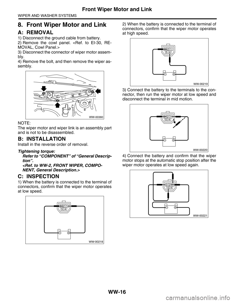
8. Front Wiper Motor and Link
A: REMOVAL
1) Disconnect the ground cable from battery.
2) Remove the cowl panel.
MOVAL, Cowl Panel.>
3) Disconnect the connector of wiper motor assem-
bly.
4) Remove the bolt, and then remove the wiper as-
sembly.
NOTE:
The wiper motor and wiper link is an assembly part
and is not to be disassembled.
B: INSTALLATION
Install in the reverse order of removal.
Tightening torque:
Refer to “COMPONENT” of “General Descrip-
tion”.
NENT, General Description.>
C: INSPECTION
1) When the battery is connected to the terminal of
connectors, confirm that the wiper motor operates
at low speed.
2) When the battery is connected to the terminal of
connectors, confirm that the wiper motor operates
at high speed.
3) Connect the battery to the terminals to the con-
nector, then run the wiper motor at low speed and
disconnect the terminal in mid motion.
4) Connect the battery and confirm that the wiper
motor stops at the automatic stop position after the
wiper motor operates at low speed again.
WW-00360
WW-00218
32541
32541
WW-00219
WW-00220
32541
WW-00221
32541
Page 713 of 2453
WW-18
Rear Wiper Arm
WIPER AND WASHER SYSTEMS
10.Rear Wiper Arm
A: REMOVAL
1) Detach the wiper arm cover (A).
2) Remove the nut (B) to remove the wiper arm.
B: INSTALLATION
1) Install in the reverse order of removal.
2) Operate the rear wiper once.
3) Align the blade with the marking (A) of the glass.
Tightening torque:
Refer to “COMPONENT” of “General Descrip-
tion”.
General Description.>
C: ADJUSTMENT
1) Operate the rear wiper once.
2) Align the blade with the marking (A) of the glass.
WW-00179
(A)
(B)
WW-00361
(A)
WW-00361
(A)
Page 714 of 2453

WW-19
Rear Wiper Motor
WIPER AND WASHER SYSTEMS
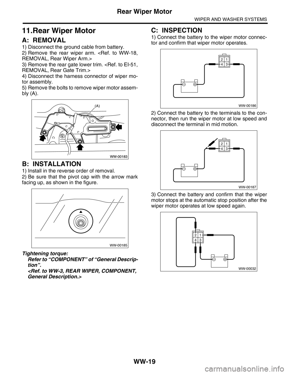
11.Rear Wiper Motor
A: REMOVAL
1) Disconnect the ground cable from battery.
2) Remove the rear wiper arm.
REMOVAL, Rear Wiper Arm.>
3) Remove the rear gate lower trim.
REMOVAL, Rear Gate Trim.>
4) Disconnect the harness connector of wiper mo-
tor assembly.
5) Remove the bolts to remove wiper motor assem-
bly (A).
B: INSTALLATION
1) Install in the reverse order of removal.
2) Be sure that the pivot cap with the arrow mark
facing up, as shown in the figure.
Tightening torque:
Refer to “COMPONENT” of “General Descrip-
tion”.
General Description.>
C: INSPECTION
1) Connect the battery to the wiper motor connec-
tor and confirm that wiper motor operates.
2) Connect the battery to the terminals to the con-
nector, then run the wiper motor at low speed and
disconnect the terminal in mid motion.
3) Connect the battery and confirm that the wiper
motor stops at the automatic stop position after the
wiper motor operates at low speed again.
WW-00185
WW-00186
21
43
WW-00187
21
43
WW-00032
21
43
Page 718 of 2453
BR-4
General Description
BRAKE
B: COMPONENT
1. FRONT DISK BRAKE
(1) Caliper body (9) Support (16) Disc cover
(2) Air bleeder screw (10) Pad clip (17) Bushing
(3) Guide pin (Green) (11) Outer shim
(4) Pin boot (12) Inner shimTightening torque: N·m (kgf-m, ft-lb)
(5) Piston seal (13) Pad (Outside)T1: 8 (0.8, 5.8)
(6) Piston (14) Pad (Inside)T2: 27 (2.8, 19.9)
(7) Piston boot (15) Disc rotorT3: 120 (12.2, 88.5)
(8) Lock pin (Yellow)
BR-00490
(1)
(2)
(3)
(4)
(4)
(17)(10)
(16)
(15)
(5)
(6)(7)
(8)
T2
T3
(11)
(11)
(12)
(12)
(13)
(14)
(13)
T1
(9)
Page 719 of 2453
BR-5
General Description
BRAKE
2. REAR DISC BRAKE
(1) Caliper body (13) Outer pad (25) Secondary shoe return spring
(2) Air bleeder screw (14) Shim (26) Primary shoe return spring
(3) Guide pin (Green) (15) Shoe hold pin (27) Adjusting spring
(4) Pin boot (16) Cover (28) Adjuster
(5) Piston seal (17) Back plate (29) Brake shoe cup
(6) Piston (18) Retainer (30) Brake shoe spring
(7) Piston boot (19) Spring washer
(8) Support (20) Parking brake leverTightening torque: N·m (kgf-m, ft-lb)
(9) Lock pin (Yellow) (21) Parking brake shoe (Secondary)T1: 8 (0.8, 5.8)
(10) Bushing (22) Parking brake shoe (Primary)T2: 27 (2.8, 19.9)
(11) Pad clip (23) StrutT3: 37 (3.7, 27.2)
(12) Inner pad (24) Strut shoe springT4: 66 (6.7, 48.7)