2009 NISSAN LATIO relay
[x] Cancel search: relayPage 2815 of 4331
![NISSAN LATIO 2009 Service Repair Manual DTC P2118 THROTTLE CONTROL MOTOR
EC-1459
< SERVICE INFOMATION >
[MR TYPE 2] C
D E
F
G H
I
J
K L
M A EC
NP
O
Do not use ECM ground terminals wh
en measuring input/output voltage. Doing so may result in NISSAN LATIO 2009 Service Repair Manual DTC P2118 THROTTLE CONTROL MOTOR
EC-1459
< SERVICE INFOMATION >
[MR TYPE 2] C
D E
F
G H
I
J
K L
M A EC
NP
O
Do not use ECM ground terminals wh
en measuring input/output voltage. Doing so may result in](/manual-img/5/57359/w960_57359-2814.png)
DTC P2118 THROTTLE CONTROL MOTOR
EC-1459
< SERVICE INFOMATION >
[MR TYPE 2] C
D E
F
G H
I
J
K L
M A EC
NP
O
Do not use ECM ground terminals wh
en measuring input/output voltage. Doing so may result in dam-
age to the ECM's transistor. Use a ground ot her than ECM terminals, such as the ground.
: Average voltage for pulse signal (Actual pulse signal can be confirmed by oscilloscope.)
Diagnosis Procedure INFOID:00000000045003521.
CHECK GROUND CONNECTIONS
1. Turn ignition switch OFF.
2. Loosen and retighten engine screw on the body. Refer to EC-1144, " Ground Inspection " .
OK or NG OK >> GO TO 2.
NG >> Repair or replace ground connections. 2.
CHECK THROTTLE CONTROL MOTOR OUTPUT SIGNAL CIRCUIT FOR OPEN OR SHORT
TERMI-
NAL
NO. WIRE
COLOR ITEM CONDITION DATA (DC Voltage)
1 L Throttle control motor
(Open) [Ignition switch: ON]
• Engine stopped
• Shift lever: D (A/T, CVT), 1st (M/T)
• Accelerator pedal: Fully depressed Approximately 3.2V
2 SB Throttle control motor power
supply [Ignition switch: ON] BATTERY VOLTAGE
(11 - 14V)
4 P Throttle control motor (Close) [Ignition switch: ON]
• Engine stopped
• Shift lever: D (A/T, CVT), 1st (M/T)
• Accelerator pedal: Fully released Approximately 1.8V
15 Y Throttle control motor relay [Ignition switch: OFF]
BATTERY VOLTAGE
(11 - 14V)
[Ignition switch: ON] 0 - 1.0V PBIA8150J
PBIA8149J
:
Vehicle front
1. Body ground E24 2. Engine ground F9 3. Engine ground F16
4. Body ground E15 BBIA0698E
Page 2869 of 4331
![NISSAN LATIO 2009 Service Repair Manual FUEL PUMP
EC-1513
< SERVICE INFOMATION >
[MR TYPE 2] C
D E
F
G H
I
J
K L
M A EC
NP
O
FUEL PUMP
Description INFOID:0000000004500415
SYSTEM DESCRIPTION
*: ECM determines the start signal status by the s NISSAN LATIO 2009 Service Repair Manual FUEL PUMP
EC-1513
< SERVICE INFOMATION >
[MR TYPE 2] C
D E
F
G H
I
J
K L
M A EC
NP
O
FUEL PUMP
Description INFOID:0000000004500415
SYSTEM DESCRIPTION
*: ECM determines the start signal status by the s](/manual-img/5/57359/w960_57359-2868.png)
FUEL PUMP
EC-1513
< SERVICE INFOMATION >
[MR TYPE 2] C
D E
F
G H
I
J
K L
M A EC
NP
O
FUEL PUMP
Description INFOID:0000000004500415
SYSTEM DESCRIPTION
*: ECM determines the start signal status by the signals of engine speed and battery voltage.
The ECM activates the fuel pump for several seconds after the ignition switch is turned ON to improve engine
start ability. If the ECM receives a engine speed signal from the crankshaft position sensor (POS) and cam-
shaft position sensor (PHASE), it knows that the engi ne is rotating, and causes the pump to operate. If the
engine speed signal is not received when the ignition s witch is ON, the engine stalls. The ECM stops pump
operation and prevents battery discharging, thereby improving safety. The ECM does not directly drive the fuel
pump. It controls the ON/OFF fuel pump rela y, which in turn controls the fuel pump.
COMPONENT DESCRIPTION A turbine type design fuel pump is used in the fuel tank.
• Fuel level sensor unit and fuel pump (1)
• Fuel pressure regulator (2)
• Fuel level sensor (3)
• Fuel tank temperature sensor (4)
CONSULT-III Reference Val ue in Data Monitor Mode INFOID:0000000004500416
Specification data are reference values. Sensor Input Signal to ECM ECM Function Actuator
Crankshaft position sensor (POS)
Camshaft position sensor (PHASE) Engine speed*
Fuel pump control Fuel pump relay
Battery Battery voltage* Condition Fuel pump operation
Ignition switch is turned to ON Operates for 1 second
Engine running and cranking Operates
Engine: Stopped Stops in 1.5 seconds
Except as shown above Stops BBIA0704E
MONITOR ITEM CONDITION SPECIFICATION
FUEL PUMP RLY • For 1 second after turning ignition switch ON
• Engine running or cranking ON
• Except above conditions OFF
Page 2871 of 4331
![NISSAN LATIO 2009 Service Repair Manual FUEL PUMP
EC-1515
< SERVICE INFOMATION >
[MR TYPE 2] C
D E
F
G H
I
J
K L
M A EC
NP
O
Diagnosis Procedure
INFOID:00000000045004181.
CHECK OVERALL FUNCTION
1. Turn ignition switch ON.
2. Pinch fuel feed NISSAN LATIO 2009 Service Repair Manual FUEL PUMP
EC-1515
< SERVICE INFOMATION >
[MR TYPE 2] C
D E
F
G H
I
J
K L
M A EC
NP
O
Diagnosis Procedure
INFOID:00000000045004181.
CHECK OVERALL FUNCTION
1. Turn ignition switch ON.
2. Pinch fuel feed](/manual-img/5/57359/w960_57359-2870.png)
FUEL PUMP
EC-1515
< SERVICE INFOMATION >
[MR TYPE 2] C
D E
F
G H
I
J
K L
M A EC
NP
O
Diagnosis Procedure
INFOID:00000000045004181.
CHECK OVERALL FUNCTION
1. Turn ignition switch ON.
2. Pinch fuel feed hose (1) with two fingers.
- Illustration shows the view with intake air duct removed.
OK or NG OK >>
INSPECTION END
NG >> GO TO 2. 2.
CHECK FUEL PUMP POWER SUPPLY CIRCUIT-I
1. Turn ignition switch OFF.
2. Disconnect ECM harness connector.
3. Turn ignition switch ON.
4. Check voltage between ECM terminal 23 and ground with CON-
SULT-III or tester.
OK or NG OK >> GO TO 5.
NG >> GO TO 3. 3.
CHECK FUEL PUMP POWER SUPPLY CIRCUIT-II
1. Turn ignition switch OFF.
2. Disconnect IPDM E/R harness connector E46.
3. Turn ignition switch ON.
4. Check voltage between IPDM E/R terminal 47 and ground with
CONSULT-III or tester.
OK or NG OK >> GO TO 4.
NG >> GO TO 11.
TERMI-
NAL NO. WIRE
COLOR ITEM CONDITION DATA (DC Voltage)
23 GR Fuel pump relay [Ignition switch: ON]
• For 1 second after turning ignition switch ON
[Engine is running] 0 - 1.0V
[Ignition switch: ON]
• More than 1 second after turning ignition
switch ON BATTERY VOLTAGE
(11 - 14V) Fuel pressure pulsation should
be felt on the fuel feed
hose for 1 second after ignition switch is turned ON. BBIA0712E
Voltage: Battery voltage
PBIA9573J
Voltage: Battery voltage
PBIB3319E
Page 3282 of 4331
GI
N
O P
• Close the relay and probe at the solenoid.
voltage; open is further down the circuit than the solenoid.
no voltage; open is between relay and solenoid (point C).
Any powered circuit can be diagnosed using the approach in the previous example.
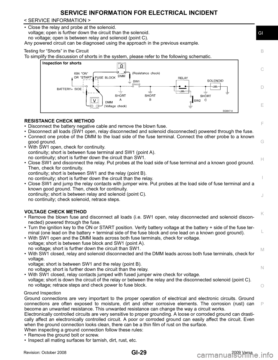
Testing for “Shorts” in the Circuit To simplify the discussion of shorts in the system, please refer to the following schematic.
RESISTANCE CHECK METHOD
• Disconnect the battery negative cable and remove the blown fuse.
• Disconnect all loads (SW1 open, relay disconnected and solenoid disconnected) powered through the fuse.
• Connect one probe of the DMM to the load side of the fuse terminal. Connect the other probe to a known
good ground.
• With SW1 open, check for continuity.
continuity; short is between fuse terminal and SW1 (point A).
no continuity; short is further down the circuit than SW1.
• Close SW1 and disconnect the relay. Put probes at the load side of fuse terminal and a known good ground.
Then, check for continuity.
continuity; short is between SW1 and the relay (point B).
no continuity; short is further down the circuit than the relay.
• Close SW1 and jump the relay contacts with jumper wir e. Put probes at the load side of fuse terminal and a
known good ground. Then, check for continuity.
continuity; short is between relay and solenoid (point C).
no continuity; check solenoid, retrace steps.
VOLTAGE CHECK METHOD
• Remove the blown fuse and disconnect all loads (i .e. SW1 open, relay disconnected and solenoid discon-
nected) powered through the fuse.
• Turn the ignition key to the ON or START position. Veri fy battery voltage at the battery + side of the fuse ter-
minal (one lead on the battery + terminal side of the fuse block and one lead on a known good ground).
• With SW1 open and the DMM leads across both fuse terminals, check for voltage.
voltage; short is between fuse block and SW1 (point A).
no voltage; short is further down the circuit than SW1.
• With SW1 closed, relay and solenoid disconnected and t he DMM leads across both fuse terminals, check for
voltage.
voltage; short is between SW1 and the relay (point B).
no voltage; short is further down the circuit than the relay.
• With SW1 closed, relay contacts jumped with fused jumper wire check for voltage.
voltage; short is down the circuit of the relay or between the relay and the disconnected solenoid (point C).
no voltage; retrace steps and check power to fuse block.
Ground Inspection Ground connections are very important to the proper oper ation of electrical and electronic circuits. Ground
connections are often exposed to moisture, dirt and other corrosive elements. The corrosion (rust) can
become an unwanted resistance. This unwanted re sistance can change the way a circuit works.
Electronically controlled circuits are very sensitive to proper grounding. A loose or corroded ground can drasti-
cally affect an electronically controlled circuit. A poor or corroded ground can easily affect the circuit. Even
when the ground connection looks clean, there can be a thin film of rust on the surface.
When inspecting a ground connection follow these rules:
• Remove the ground bolt or screw.
• Inspect all mating surfaces for tarnish, dirt, rust, etc.
Page 3354 of 4331
GW
N
O P
REAR WINDOW DEFOGGER
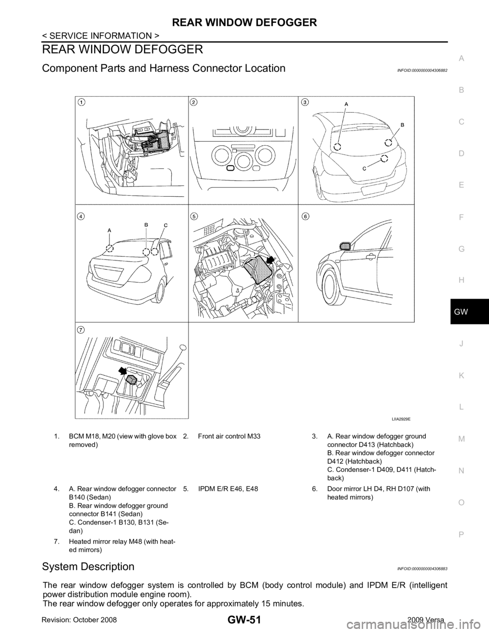
Component Parts and Har ness Connector Location INFOID:0000000004306882
System Description INFOID:0000000004306883
The rear window defogger system is controlled by BCM (body control module) and IPDM E/R (intelligent
power distribution module engine room).
The rear window defogger only operates for approximately 15 minutes. 1. BCM M18, M20 (view with glove box
removed) 2. Front air control M33 3. A. Rear window defogger ground
connector D413 (Hatchback)
B. Rear window defogger connector
D412 (Hatchback)
C. Condenser-1 D4 09, D411 (Hatch-
back)
4. A. Rear window defogger connector B140 (Sedan)
B. Rear window defogger ground
connector B141 (Sedan)
C. Condenser-1 B130, B131 (Se-
dan) 5. IPDM E/R E46, E48 6. Door mirror LH D4, RH D107 (with
heated mirrors)
7. Heated mirror relay M48 (with heat- ed mirrors)
Page 3363 of 4331
OK >> Check condition of harness and connector.
NG >> Replace IPDM E/R. Refer to PG-27, " Removal and Installation of IPDM E/R " .
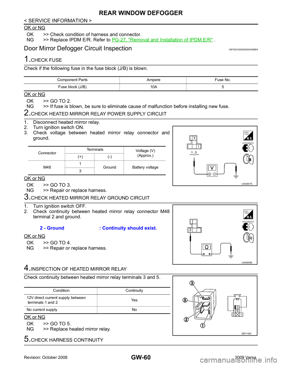
Door Mirror Defogger Circuit Inspection INFOID:0000000004306894OK >> GO TO 2.
NG >> If fuse is blown, be sure to eliminate cause of malfunction before installing new fuse. OK >> GO TO 3.
NG >> Repair or replace harness. OK >> GO TO 4.
NG >> Repair or replace harness. OK >> GO TO 5.
NG >> Replace heated mirror relay. Connector
Terminals
Voltage (V)
(Approx.)
(+) (-)
M48 1
Ground Battery voltage
3
Page 3364 of 4331
GW
N
O P
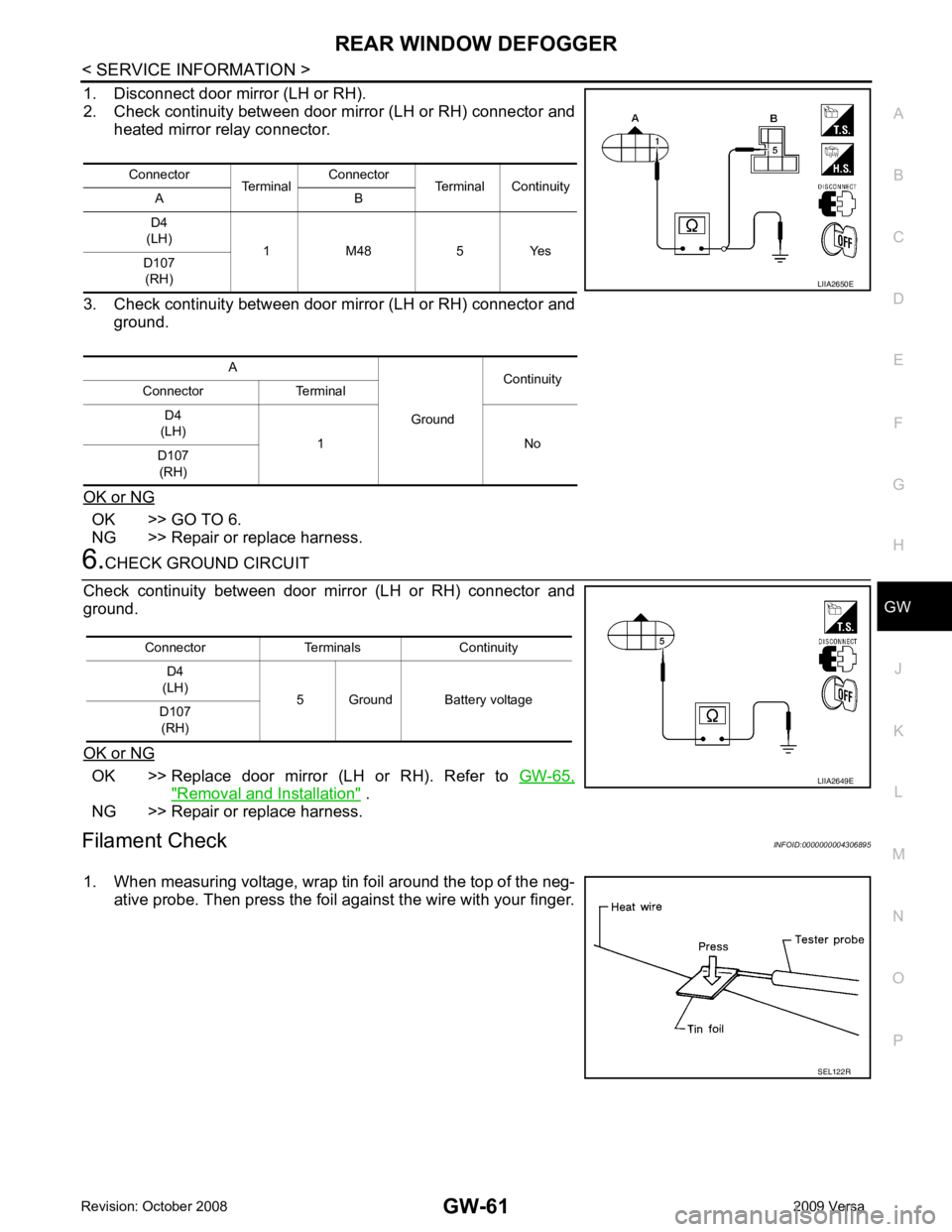
1. Disconnect door mirror (LH or RH).
2. Check continuity between door mirror (LH or RH) connector and heated mirror relay connector.
3. Check continuity between door mirror (LH or RH) connector and ground.
OK or NG OK >> GO TO 6.
NG >> Repair or replace harness. OK >> Replace door mirror (LH or RH). Refer to
GW-65," Removal and Installation " .
NG >> Repair or replace harness.
Filament Check INFOID:0000000004306895
1. When measuring voltage, wrap tin foil around the top of the neg- ative probe. Then press the foil against the wire with your finger.Connector
TerminalConnector
Terminal Continuity
A B
D4
(LH) 1 M48 5 Yes
D107
(RH)
A GroundContinuity
Connector Terminal
D4
(LH) 1 No
D107
(RH) SEL122R
Page 3611 of 4331
LT
N
O P
• to BCM terminal 67
• to combination meter terminals 21, 22 and 23
• through grounds M57 and M61, and
• to IPDM E/R terminals 39 and 59
• through grounds E15 and E24.
HEADLAMP OPERATION
Low Beam Operation With the lighting switch in 2ND position, the BCM re ceives an input signal requesting the headlamps to illumi-
nate. The BCM then sends a signal, via the CAN comm unication lines, to the IPDM E/R requesting the low
beam headlamps be turned ON. The CPU located in the IPDM E/R controls ground to the headlamp low relay
coil, which when energized, directs power
• through 15A fuse (No. 41, located in IPDM E/R)
• through IPDM E/R terminal 54
• to headlamp RH terminal 3, and
• through 15A fuse (No. 40, located in IPDM E/R)
• through IPDM E/R terminal 52
• to headlamp LH terminal 3.
Ground is supplied
• to headlamp RH and LH terminals 2
• through grounds E15 and E24.
With power and ground supplied, low beam headlamps illuminate.
High Beam Operation/Flash-to-Pass Operation With the lighting switch in 2ND position and high beam s witch in the HIGH position, the BCM receives an input
signal requesting the headlamp high beams to illuminate. The flash to pass feature can be used any time and
also sends a signal to the BCM. This input signal is then communicated to the IPDM E/R and the combination
meter via the CAN communication. The CPU located in the IPDM E/R controls the headlamp high relays (LH
and RH), which when energized, directs power
• through 10A fuse (No. 34, located in IPDM E/R)
• through IPDM E/R terminal 56
• to headlamp RH terminal 1, and
• through 10A fuse (No. 35, located in IPDM E/R)
• through IPDM E/R terminal 55
• to headlamp LH terminal 1.
Ground is supplied
• to headlamp RH and LH terminal 2
• through grounds E15 and E24.
With power and ground supplied, the high beam headlamps illuminate.
The BCM sends a signal, via the CAN communication lines, to the combination meter requesting the high
beam indicator lamp be turned ON.
COMBINATION SWITCH READING FUNCTION Refer to BCS-3, " System Description " .
EXTERIOR LAMP BATTERY SAVER CONTROL Refer to LT-73, " System Description " .
CAN COMMUNICATION SYSTEM DESCRIPTION INFOID:0000000004306522
Refer to LAN-8 .