2009 NISSAN LATIO relay
[x] Cancel search: relayPage 3618 of 4331

Test item Description
TAIL LAMP Allows tail lamp relay to operate by switching ON-OFF.
HEAD LAMP Allows headlamp relay (HI, LO) to operate by switching ON-OFF.
FR FOG LAMP Allows fog lamp relay to operate by switching ON-OFF. Monitored item CONSULT-llI display Description
CAN communication CAN communication [U1000] Malfunction is detected in CAN communication.
CAN communication system CAN communication system 1 to 6 [U1000] Malfunction is detected in CAN system. IPDM E/R diagnostic Mode Description
SELF-DIAG RESULTS Displays IPDM E/R self-diagnosis results. DATA MONITOR Displays IPDM E/R in put/output data in real time.
CAN DIAG SUPPORT MNTR The result of transmit/receive diagnosis of CAN communication can be read. ACTIVE TEST Operation of electrical loads can be checked by sending drive signal to them.
Page 3619 of 4331
LT
N
O P
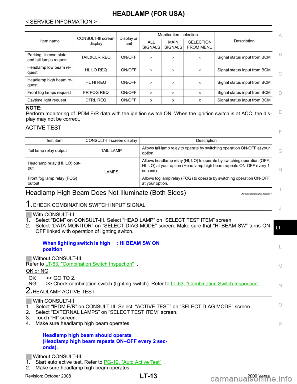
NOTE:
Perform monitoring of IPDM E/R data with the ignition swit ch ON. When the ignition switch is at ACC, the dis-
play may not be correct.
ACTIVE TEST
Headlamp High Beam Does No t Illuminate (Both Sides) INFOID:0000000004306531Combination Switch Inspection " .
OK or NG OK >> GO TO 2.
NG >> Check combination switch (lighting switch). Refer to LT-63, " Combination Switch Inspection " .
Auto Active Test " .
2. Make sure headlamp high beam operates. Item name
CONSULT-III screen
display Display or
unit Monitor item selection
Description
ALL
SIGNALS MAIN
SIGNALS SELECTION
FROM MENU
Parking, license plate
and tail lamps request TAIL&CLR REQ ON/OFF
× × ×Signal status input from BCM
Headlamp low beam re-
quest HL LO REQ ON/OFF
× × × Signal status input from BCM
Headlamp high beam re-
quest HL HI REQ ON/OFF
× × × Signal status input from BCM
Front fog lamps request FR FOG REQ ON/OFF × × ×Signal status input from BCM
Daytime light request DTRL REQ ON/OFF x x x Signal status input from BCM Test item CONSULT-III screen display Description
Tail lamp relay output TAIL LAMP Allows tail lamp relay to operate by switching operation ON-OFF at your
option.
Headlamp relay (HI, LO) out-
put LAMPSAllows headlamp relay (HI, LO) to operate by switching operation (OFF,
HI, LO) at your option (Head lamp high beam repeats ON-OFF every 1
second).
Front fog lamp relay (FOG)
output Allows fog lamp relay (FOG) to operate by switching operation ON-OFF
at your option. Headlamp high beam should operate
(Headlamp high beam repeats ON–OFF every 2 sec-
onds).
Page 3631 of 4331
LT
N
O P
HEADLAMP (FOR CANADA)
- DAYTIME LIGHT SYSTEM -
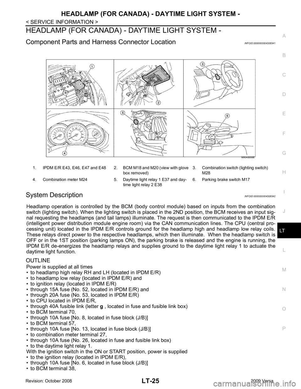
Component Parts and Har ness Connector Location INFOID:0000000004306541
System Description INFOID:0000000004306542
Headlamp operation is controlled by the BCM (body c ontrol module) based on inputs from the combination
switch (lighting switch). When the lighting switch is pl aced in the 2ND position, the BCM receives an input sig-
nal requesting the headlamps (and tail lamps) illuminate. The request is then communicated to the IPDM E/R
(intelligent power distribution module engine room) vi a the CAN communication lines. The CPU (central pro-
cessing unit) located in the IPDM E/R controls ground for the headlamp high and headlamp low relay coils.
These relays direct power to the respective headlamps , which then illuminate. When the headlamp switch is
OFF or in the 1ST position (parking lamps ON), the parking brake is released and the engine is running, the
IPDM E/R de-energizes the headlamp relays and supplies gr ound to the daytime light relay 1 to actuate the
daytime light function.
OUTLINE Power is supplied at all times
• to headlamp high relay RH and LH (located in IPDM E/R)
• to headlamp low relay (located in IPDM E/R) and
• to ignition relay (located in IPDM E/R)
• through 15A fuse (No. 52, located in IPDM E/R) and
• through 20A fuse (No. 53, located in IPDM E/R)
• to CPU located in IPDM E/R,
• through 40A fusible link (letter g , located in fuse and fusible link box)
• to BCM terminal 70,
• through 10A fuse [No. 8, located in fuse block (J/B)]
• to BCM terminal 57,
• through 10A fuse [No. 13, located in fuse block (J/B)]
• to combination meter terminal 27,
• through 10A fuse (No. 26, located in fuse and fusible link box)
• to the daytime light relay 1.
With the ignition switch in the ON or START position, power is supplied
• to the ignition relay (located in IPDM E/R),
• through 10A fuse [No. 6, located in fuse block (J/B)]
• to BCM terminal 38, 1. IPDM E/R E43, E46, E47 and E48 2. BCM M18 and M20 (view with glove
box removed)3. Combination switch (lighting switch)
M28
4. Combination meter M24 5. Daytime light relay 1 E37 and day- time light relay 2 E386. Parking brake switch M17
Page 3633 of 4331
LT
N
O P
• to IPDM E/R terminal 56,
• through 10A fuse (No. 34, located in IPDM E/R) and
• through both de-energized headlamp high relays
• to 10A fuse (No. 35, located in IPDM E/R),
• through IPDM E/R terminal 55
• to front combination lamp LH terminal high beam 1.
Ground is supplied
• to front combination lamp LH terminal 2
• through grounds E15 and E24,
• to daytime light relay 1 terminal 1
• through IPDM E/R terminal 6.
With power and ground supplied, high beam headlamps illuminate at reduced intensity.
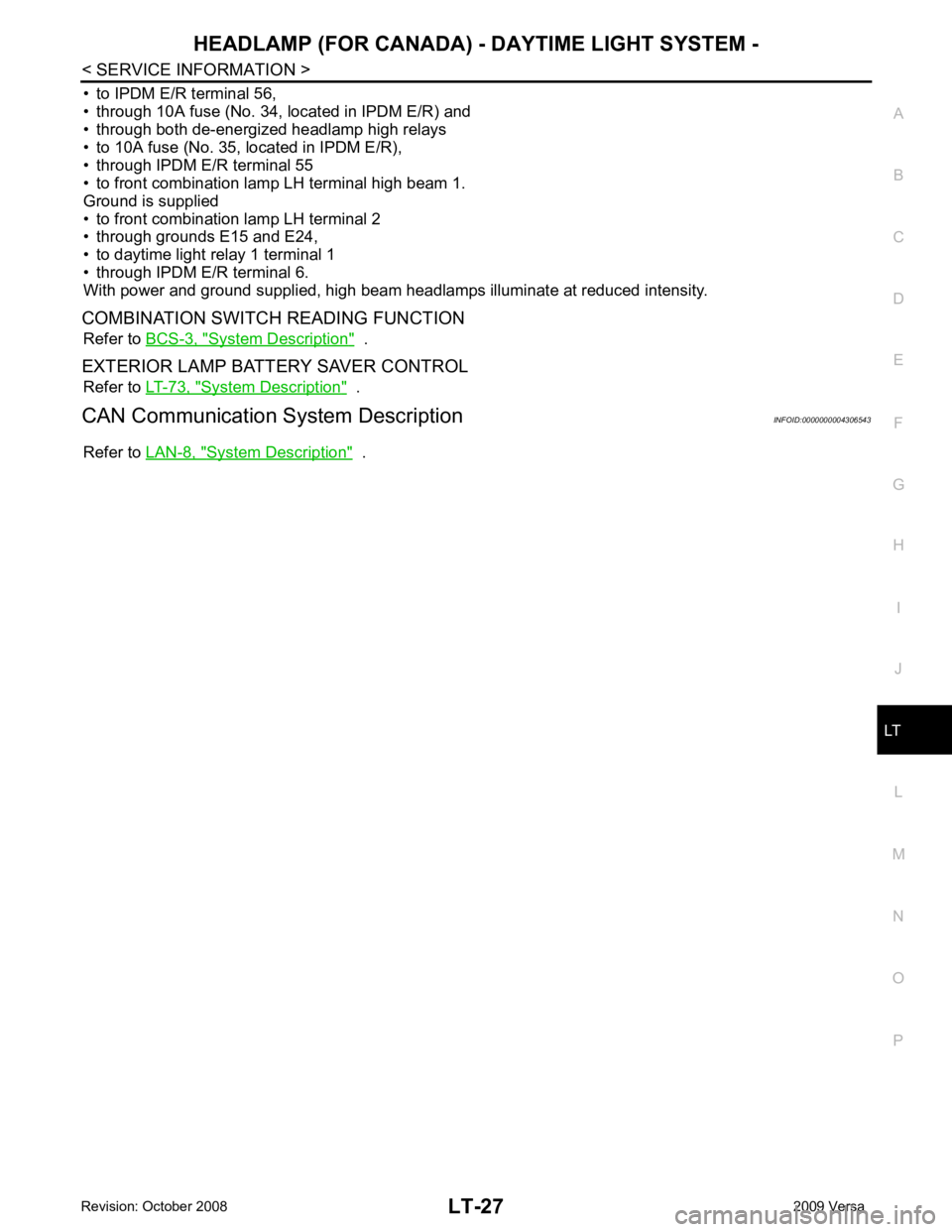
COMBINATION SWITCH READING FUNCTION Refer to BCS-3, " System Description " .
EXTERIOR LAMP BATTERY SAVER CONTROL Refer to LT-73, " System Description " .
CAN Communication System Description INFOID:0000000004306543
Refer to LAN-8, " System Description " .
Page 3640 of 4331
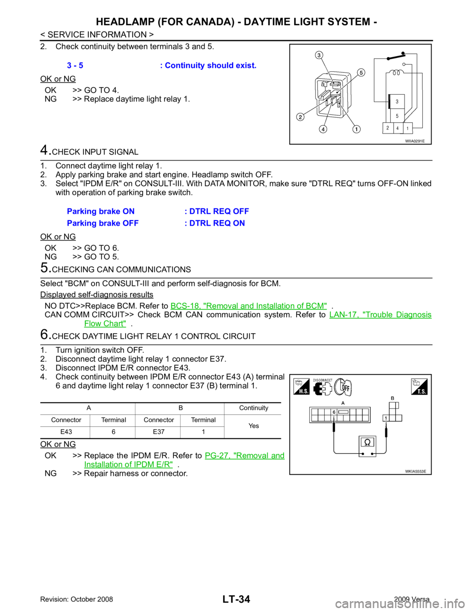
OK >> GO TO 4.
NG >> Replace daytime light relay 1. OK >> GO TO 6.
NG >> GO TO 5. NO DTC>>Replace BCM. Refer to
BCS-18, " Removal and Installation of BCM " .
CAN COMM CIRCUIT>> Check BCM CAN communication system. Refer to LAN-17, " Trouble Diagnosis
Flow Chart " .
OK >> Replace the IPDM E/R. Refer to
PG-27, " Removal and
Installation of IPDM E/R " .
NG >> Repair harness or connector. 3 - 5 : Continuity should exist.
Page 3645 of 4331
LT
N
O P
FRONT FOG LAMP
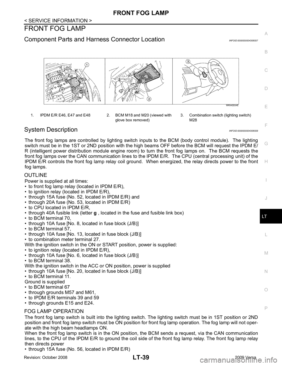
Component Parts and Har ness Connector Location INFOID:0000000004306557
System Description INFOID:0000000004306558
The front fog lamps are controlled by lighting switch inputs to the BCM (body control module). The lighting
switch must be in the 1ST or 2ND position with t he high beams OFF before the BCM will request the IPDM E/
R (intelligent power distribution module engine room) to turn the front fog lamps on. The BCM requests the
front fog lamps over the CAN communication lines to the IPDM E/R. The CPU (central processing unit) of the
IPDM E/R controls the front fog lamp relay coil ground. When energized, the relay directs power to the front
fog lamps.
OUTLINE Power is supplied at all times:
• to front fog lamp relay (located in IPDM E/R),
• to ignition relay (located in IPDM E/R),
• through 15A fuse (No. 52, located in IPDM E/R) and
• through 20A fuse (No. 53, located in IPDM E/R)
• to CPU located in IPDM E/R,
• through 40A fusible link (letter g , located in the fuse and fusible link box)
• to BCM terminal 70,
• through 10A fuse [No. 8, located in fuse block (J/B)]
• to BCM terminal 57,
• through 10A fuse [No. 13, located in fuse block (J/B)]
• to combination meter terminal 27.
With the ignition switch in the ON or START position, power is supplied:
• to ignition relay (located in IPDM E/R),
• through 10A fuse [No. 6, located in fuse block (J/B)]
• to BCM terminal 38.
With the ignition switch in the ACC or ON position, power is supplied
• through 10A fuse [No. 20, located in fuse block (J/B)]
• to BCM terminal 11.
Ground is supplied
• to BCM terminal 67
• through grounds M57 and M61,
• to IPDM E/R terminals 39 and 59
• through grounds E15 and E24.
FOG LAMP OPERATION The front fog lamp switch is built into the lighting s witch. The lighting switch must be in 1ST position or 2ND
position and front fog lamp switch must be ON position fo r front fog lamp operation. The fog lamp will not oper-
ate with the high beam headlamps ON.
When the front fog lamp switch is in the ON positi on, the BCM sends a request, via the CAN communication
lines, to the CPU of the IPDM E/R to ground the coil side of the front fog lamp relay. The front fog lamp relay
then directs power
• through 15A fuse (No. 56, located in IPDM E/R) 1. IPDM E/R E46, E47 and E48 2. BCM M18 and M20 (viewed with
glove box removed)3. Combination switch (lighting switch)
M28
Page 3650 of 4331
Auto Active Test " .
2. Make sure front fog lamp operates.
OK or NG OK >> GO TO 4.
NG >> GO TO 5. OK >> Replace IPDM E/R. Refer to
PG-27, " Removal and Installation of IPDM E/R " .
NG >> Replace BCM. Refer to BCS-18, " Removal and Installation of BCM " .
Auto Active Test " .
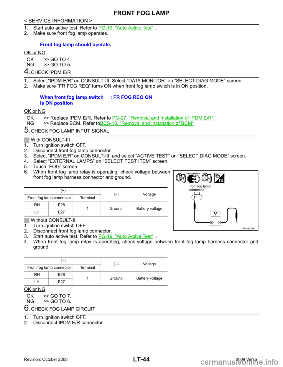
4. When front fog lamp relay is operating, chec k voltage between front fog lamp harness connector and
ground.
OK or NG OK >> GO TO 7.
NG >> GO TO 6.
Page 3655 of 4331

LT
N
O P
• to rear combination lamp LH terminal 1
• through grounds B7 and B19.
The BCM also sends a request, via the CAN communication lines, to the combination meter to flash the left
turn signal indicator. The unified meter control unit in the combination meter supplies ground to the left turn
signal indicator lamp and activates the audible turn signal indicator.
With power, ground and input supplied, the BCM controls the flashing of the turn signal lamps.
RH Turn Signal Lamp When turn signal switch is moved to the right turn position, the BCM receives an input signal requesting right
turn signals to flash. The BCM then supplies power
• through BCM terminal 61
• to front combination lamp RH terminal 4 and
• to rear combination lamp RH terminal 6.
Ground is supplied
• to front combination lamp RH terminal 5
• through grounds E15 and E24,
• to rear combination lamp RH terminal 1
• through grounds B117, B132 (all models) and D402 (with hatchback).
The BCM also sends a request, via the CAN communicati on lines, to the combination meter to flash the right
turn signal indicator. The unified meter control unit in the combination meter supplies ground to the right turn
signal indicator lamp and activates the audible turn signal indicator.
With power, ground and input supplied, the BCM controls the flashing of the turn signal lamps.
HAZARD LAMP OPERATION Power is supplied at all times
• through 40A fusible link (letter g , located in fuse, fusible link and relay box)
• to BCM terminal 70,
• through 10A fuse [No. 8, located in fuse block (J/B)]
• to BCM terminal 57,
• through 10A fuse [No. 13, located in fuse block (J/B)]
• to combination meter terminal 27.
Ground is supplied
• to hazard switch terminal 1,
• to BCM terminal 67, and
• to combination meter terminals 21, 22 and 23
• through grounds M57 and M61.
When hazard switch is depressed, ground is supplied
• through hazard switch terminal 2
• to BCM terminal 29.
BCM then supplies power
• to front combination lamp LH terminal 4 and
• to rear combination lamp LH terminal 6
• through BCM terminal 60,
• to front combination lamp RH terminal 4 and
• to rear combination lamp RH terminal 6
• through BCM terminal 61.
Ground is supplied
• to front combination lamp LH and RH terminal 5
• through grounds E15 and E24,
• to rear combination lamp LH terminal 1
• through grounds B7 and B19,
• to rear combination lamp RH terminal 1
• through grounds B117, B132 and D402 (hatchback).
The BCM also supplies input to combination meter ac ross the CAN communication lines. This input is pro-
cessed by unified meter control unit in combination mete r, which in turn supplies ground to the left and right
turn signal indicator lamps.
With power and input supplied, BCM controls flashing of hazard warning lamps.
REMOTE KEYLESS ENTRY SYSTEM OPERATION Power is supplied at all times
• through 40A fusible link (letter g , located in fuse, fusible link and relay box)
• to BCM terminal 70,