2009 NISSAN LATIO low oil pressure
[x] Cancel search: low oil pressurePage 42 of 4331

AT
N
O P
Control Valve
INFOID:0000000004305307
FUNCTION OF CONTROL VALVES
Centrifugal Cancel Mechanism INFOID:0000000004305308
FUNCTION The centrifugal cancel mechanism is a mechanism to c ancel the centrifugal hydraulic pressure instead of the
conventional check balls. It cancels the centrifugal hy draulic pressure which is generated as high clutch drum
rotates, and it allows for preventing high clutch from dragging and for providing stable high clutch piston press-
ing force in all revolution speeds.
STRUCTURE/OPERATION Valve name Function
Pressure regulator valve, plug and sleeve
plug Regulates oil discharged from the oil pump to provide optimum line pressure for all driving
conditions.
Pressure modifier valve and sleeve Used as a signal supplementary valve to the pressure regulator valve. Regulates pres- sure-modifier pressure (signal pressure) which controls optimum line pressure for all driv-
ing conditions.
Pilot valve Regulates line pressure to maintain a constant pilot pressure level which controls lock-up mechanism, overrun clutch, shift timing.
Accumulator control valve Regulates accumulator back-pressure to pressure suited to driving conditions.
Manual valve Directs line pressure to oil circuits corresponding to select positions. Hydraulic pressure drains when the shift lever is in Neutral.
Shift valve A Simultaneously switches three oil circuits using output pressure of shift solenoid valve A to meet driving conditions (vehicle speed, throttle opening, etc.).
Provides automatic downshifting and upshifting (1st → 2nd → 3rd → 4th gears/4th → 3rd
→ 2nd → 1st gears) in combination with shift valve B.
Shift valve B Simultaneously switches two oil circuits using output pressure of shift solenoid valve B in relation to driving conditions (vehicle speed, throttle opening, etc.).
Provides automatic downshifting and upshifting (1st → 2nd → 3rd → 4th gears/4th → 3rd
→ 2nd → 1st gears) in combination with shift valve A.
Overrun clutch control valve Switches hydraulic circuits to prevent engagement of the overrun clutch simultaneously with application of the brake band in D4. (Interlocking occurs if the overrun clutch engages
during D 4.)
1st reducing valve Reduces low & reverse brake pressure to dampen engine-brake shock when downshift- ing from the 1st position 12 to 1 1.
Overrun clutch reducing valve Reduces oil pressure directed to the overrun clutch and prevents engine-brake shock. In the 1st and 2nd positions, line pressure acts on the overrun clutch reducing valve to
increase the pressure-regulating point, with resultant engine brake capability.
Torque converter relief valve Prevents an excessive rise in torque converter pressure.
Torque converter clutch control valve, plug
and sleeve Activates or inactivates the lock-up function.
Also provides smooth lock-up through transient application and release of the lock-up
system.
1-2 accumulator valve and piston Lessens the shock find when the 2nd gear band servo contracts, and provides smooth shifting.
3-2 timing valve Switches the pace that oil pressure is released depending on vehicle speed; maximizes the high clutch release timing, and allows for soft downshifting.
Shuttle valve Determines if the overrun clutch solenoid valve should control the 3-2 timing valve or the overrun clutch control valve and switches between the two.
Cooler check valve At low speeds and with a small load when a little heat is generated, saves the volume of cooler flow, and stores the oil pressure for lock-up.
Page 60 of 4331
AT
N
O P
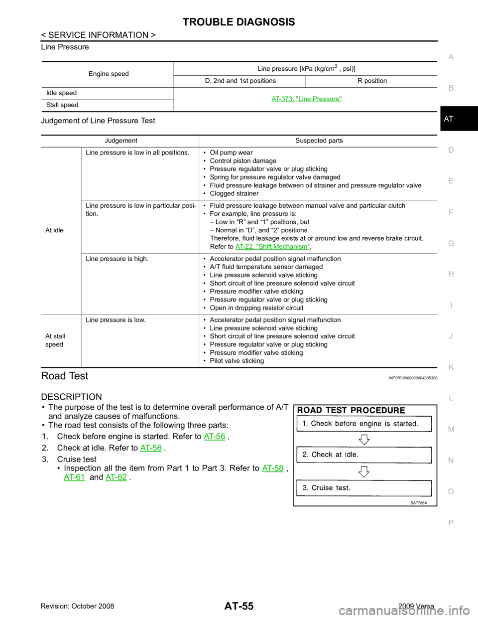
Line Pressure
Judgement of Line Pressure Test
Road Test INFOID:0000000004305320
DESCRIPTION • The purpose of the test is to det ermine overall performance of A/T
and analyze causes of malfunctions.
• The road test consists of the following three parts:
1. Check before engine is started. Refer to AT-56 .
2. Check at idle. Refer to AT-56 .
3. Cruise test • Inspection all the item from Part 1 to Part 3. Refer to AT-58 ,
AT-61 and
AT-62 .
Engine speed
Line pressure [kPa (kg/cm
2
, psi)]
D, 2nd and 1st positions R position
Idle speed AT-373, " Line Pressure "
Stall speed
Judgement Suspected parts
At idle Line pressure is low in all positions. • Oil pump wear
• Control piston damage
• Pressure regulator valve or plug sticking
• Spring for pressure regulator valve damaged
• Fluid pressure leakage between oil strainer and pressure regulator valve
• Clogged strainer
Line pressure is low in particular posi-
tion. • Fluid pressure leakage between manual valve and particular clutch
• For example, line pressure is: − Low in “R” and “1 ” positions, but
− Normal in “D”, and “2” positions.
Therefore, fluid leakage exists at or around low and reverse brake circuit.
Refer to AT-22, " Shift Mechanism " .
Line pressure is high. • Accelerator pedal position signal malfunction • A/T fluid temperature sensor damaged
• Line pressure solenoid valve sticking
• Short circuit of line pressure solenoid valve circuit
• Pressure modifier valve sticking
• Pressure regulator valve or plug sticking
• Open in dropping resistor circuit
At stall
speed Line pressure is low. • Accelerator pedal position signal malfunction
• Line pressure solenoid valve sticking
• Short circuit of line pressure solenoid valve circuit
• Pressure regulator valve or plug sticking
• Pressure modifier valve sticking
• Pilot valve sticking
Page 76 of 4331
AT
N
O P
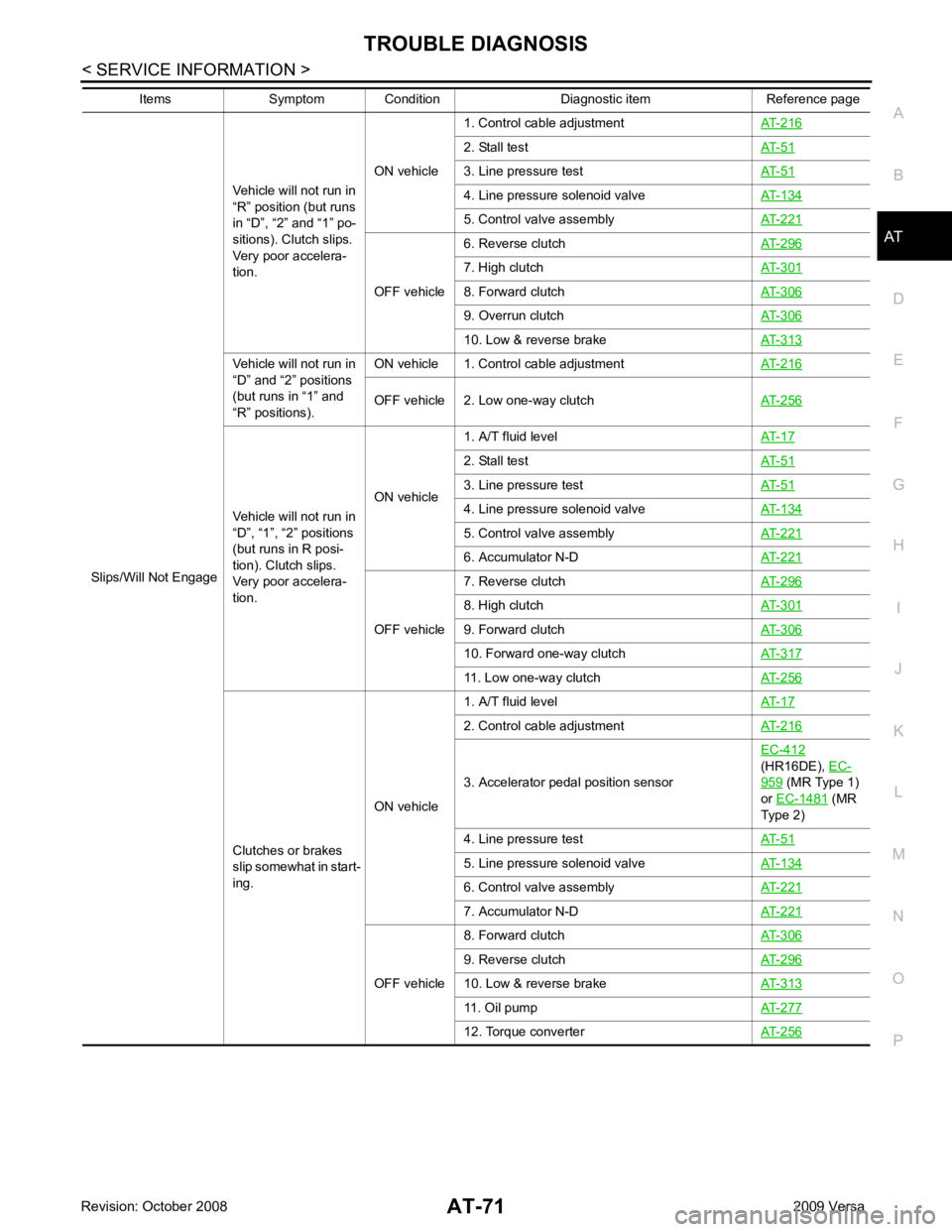
Slips/Will Not Engage
Vehicle will not run in
“R” position (but runs
in “D”, “2” and “1” po-
sitions). Clutch slips.
Very poor accelera-
tion. ON vehicle
1. Control cable adjustment
AT-216 2. Stall test
AT-51 3. Line pressure test
AT-51 4. Line pressure solenoid valve
AT-134 5. Control valve assembly
AT-221 OFF vehicle
6. Reverse clutch
AT-296 7. High clutch
AT-301 8. Forward clutch
AT-306 9. Overrun clutch
AT-306 10. Low & reverse brake
AT-313Vehicle will not run in
“D” and “2” positions
(but runs in “1” and
“R” positions). ON vehicle 1. Control cable adjustment
AT-216OFF vehicle 2. Low one-way clutch
AT-256Vehicle will not run in
“D”, “1”, “2” positions
(but runs in R posi-
tion). Clutch slips.
Very poor accelera-
tion. ON vehicle
1. A/T fluid level
AT-17 2. Stall test
AT-51 3. Line pressure test
AT-51 4. Line pressure solenoid valve
AT-134 5. Control valve assembly
AT-221 6. Accumulator N-D
AT-221 OFF vehicle
7. Reverse clutch
AT-296 8. High clutch
AT-301 9. Forward clutch
AT-306 10. Forward one-way clutch
AT-317 11. Low one-way clutch
AT-256Clutches or brakes
slip somewhat in start-
ing. ON vehicle1. A/T fluid level
AT-17 2. Control cable adjustment
AT-216 3. Accelerator pedal position sensor
EC-412
(HR16DE), EC- 959 (MR Type 1)
or EC-1481 (MR
Type 2)
4. Line pressure test AT-51 5. Line pressure solenoid valve
AT-134 6. Control valve assembly
AT-221 7. Accumulator N-D
AT-221 OFF vehicle
8. Forward clutch
AT-306 9. Reverse clutch
AT-296 10. Low & reverse brake
AT-313 11. Oil pump
AT-277 12. Torque converter
AT-256Items Symptom Condition Diagnostic item Reference page
Page 78 of 4331
AT
N
O P
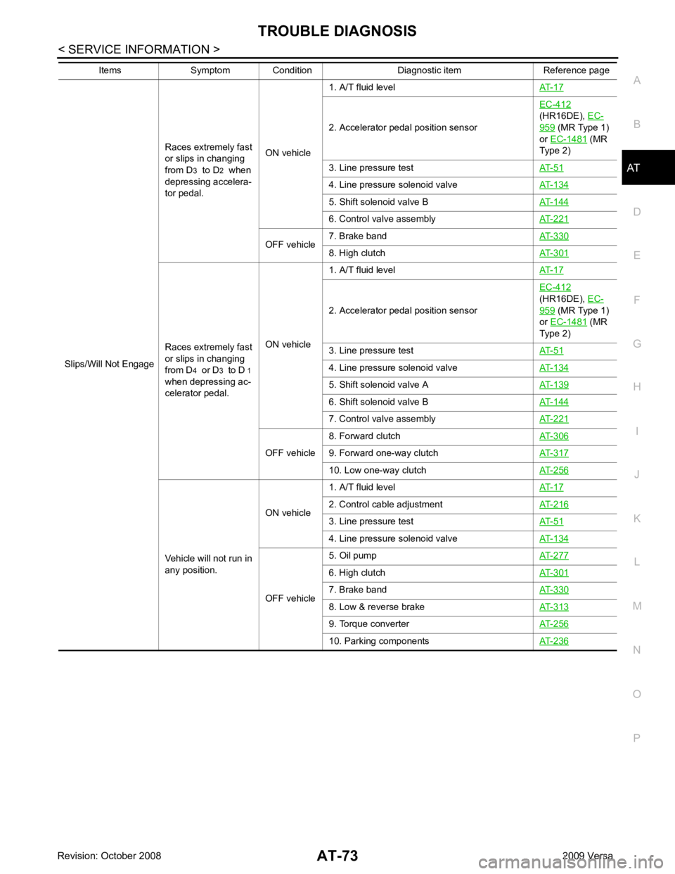
Slips/Will Not Engage
Races extremely fast
or slips in changing
from D 3 to D 2 when
depressing accelera-
tor pedal. ON vehicle1. A/T fluid level
AT-17 2. Accelerator pedal position sensor
EC-412
(HR16DE), EC- 959 (MR Type 1)
or EC-1481 (MR
Type 2)
3. Line pressure test AT-51 4. Line pressure solenoid valve
AT-134 5. Shift solenoid valve B
AT-144 6. Control valve assembly
AT-221 OFF vehicle
7. Brake band
AT-330 8. High clutch
AT-301Races extremely fast
or slips in changing
from D 4 or D 3 to D 1
when depressing ac-
celerator pedal. ON vehicle1. A/T fluid level
AT-17 2. Accelerator pedal position sensor
EC-412
(HR16DE), EC- 959 (MR Type 1)
or EC-1481 (MR
Type 2)
3. Line pressure test AT-51 4. Line pressure solenoid valve
AT-134 5. Shift solenoid valve A
AT-139 6. Shift solenoid valve B
AT-144 7. Control valve assembly
AT-221 OFF vehicle
8. Forward clutch
AT-306 9. Forward one-way clutch
AT-317 10. Low one-way clutch
AT-256Vehicle will not run in
any position. ON vehicle
1. A/T fluid level
AT-17 2. Control cable adjustment
AT-216 3. Line pressure test
AT-51 4. Line pressure solenoid valve
AT-134 OFF vehicle
5. Oil pump
AT-277 6. High clutch
AT-301 7. Brake band
AT-330 8. Low & reverse brake
AT-313 9. Torque converter
AT-256 10. Parking components
AT-236Items Symptom Condition Diagnostic item Reference page
Page 81 of 4331
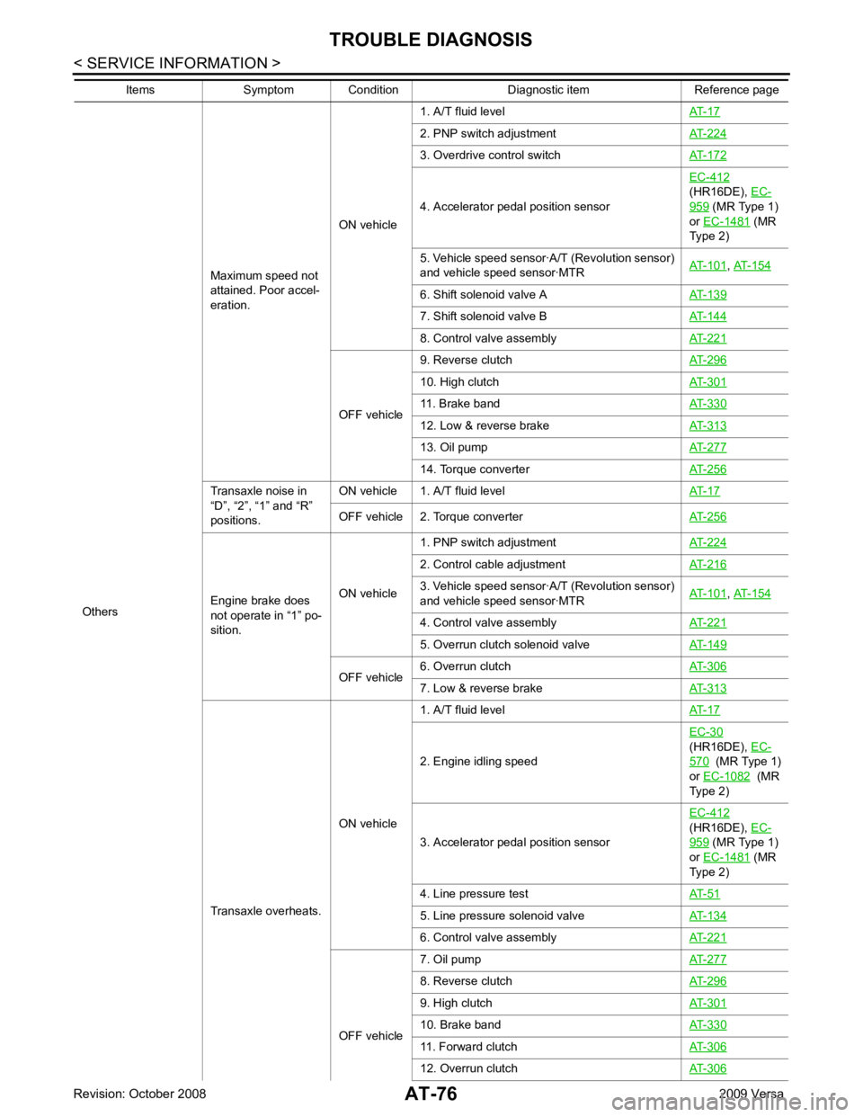
2. PNP switch adjustment
AT-224 3. Overdrive control switch
AT-172 4. Accelerator pedal position sensor
EC-412
(HR16DE), EC- 959 (MR Type 1)
or EC-1481 (MR
Type 2)
5. Vehicle speed sensor·A/T (Revolution sensor)
and vehicle speed sensor·MTR AT-101 ,
AT-154 6. Shift solenoid valve A
AT-139 7. Shift solenoid valve B
AT-144 8. Control valve assembly
AT-221 OFF vehicle
9. Reverse clutch
AT-296 10. High clutch
AT-301 11. Brake band
AT-330 12. Low & reverse brake
AT-313 13. Oil pump
AT-277 14. Torque converter
AT-256Transaxle noise in
“D”, “2”, “1” and “R”
positions. ON vehicle 1. A/T fluid level
AT-17OFF vehicle 2. Torque converter
AT-256Engine brake does
not operate in “1” po-
sition. ON vehicle1. PNP switch adjustment
AT-224 2. Control cable adjustment
AT-216 3. Vehicle speed sensor·A/T (Revolution sensor)
and vehicle speed sensor·MTR AT-101 ,
AT-154 4. Control valve assembly
AT-221 5. Overrun clutch solenoid valve
AT-149 OFF vehicle
6. Overrun clutch
AT-306 7. Low & reverse brake
AT-313Transaxle overheats.
ON vehicle1. A/T fluid level
AT-17 2. Engine idling speed
EC-30
(HR16DE), EC- 570 (MR Type 1)
or EC-1082 (MR
Type 2)
3. Accelerator pedal position sensor EC-412
(HR16DE), EC- 959 (MR Type 1)
or EC-1481 (MR
Type 2)
4. Line pressure test AT-51 5. Line pressure solenoid valve
AT-134 6. Control valve assembly
AT-221 OFF vehicle
7. Oil pump
AT-277 8. Reverse clutch
AT-296 9. High clutch
AT-301 10. Brake band
AT-330 11. Forward clutch
AT-306 12. Overrun clutch
AT-306Items Symptom Condition Diagnostic item Reference page
Page 124 of 4331

AT
N
O P
DTC P0734 A/T 4TH GEAR FUNCTION
Description INFOID:0000000004305383
• This malfunction will not be detected while the OD OFF indicator lamp is indicating another self-diagnosis malfunction.
• This malfunction is detected when the A/T does not shif t into fourth gear position or the torque converter
clutch does not lock up as instructed by the TCM. This is not caused by electrical malfunction (circuits open
or shorted) but by mechanical malfunction such as c ontrol valve sticking, improper solenoid valve operation,
malfunctioning oil pump or torque converter clutch, etc.
CONSULT-III Reference Val ue in Data Monitor Mode INFOID:0000000004305384
Remarks: Specification data are reference values.
On Board Diagnosis Logic INFOID:0000000004305385
• This is an OBD-II self-diagnostic item.
• Diagnostic trouble code “P0734 A/T 4TH GR FNCTN” with CONSULT-III is detected when A/T cannot be
shifted to the 4th gear position even if electrical circuit is good.
• This diagnosis monitors actual gear position by checki ng the torque converter slip ratio calculated by TCM
as follows:
Torque converter slip ratio = A x C/B
A: Output shaft revolution signal from revolution sensor
B: Engine speed signal from ECM
C: Gear ratio determined as gear position which TCM supposes
If the actual gear position is much lower than the pos ition (4th) supposed by TCM, the slip ratio will be much
less than normal. In case the ratio does not reach t he specified value, TCM judges this diagnosis malfunc-
tion.
This malfunction will be caused when shift solenoid valve A is stuck open or shift solenoid valve B is stuck
closed.
• Gear positions supposed by TCM are as follows.
In case of gear position with no malfunctions: 1, 2, 3 and 4 positions
In case of gear position with shift solenoid valve A stuck open: 2, 2, 3 and 3* positions
In case of gear position with shift solenoid valve B stuck closed: 1, 2, 2 and 1* positions to each gear position
above
*: “P0734 A/T 4TH GR FNCTN” is detected.
Possible Cause INFOID:0000000004305386
• Shift solenoid valve A
• Shift solenoid valve B
• Line pressure solenoid valve
• Each clutch
• Hydraulic control circuit
DTC Confirmation Procedure INFOID:0000000004305387
CAUTION:
• Always drive vehicle at a safe speed.
• If performing this “DTC Confirmation Procedure” again, always turn ignition switch OFF and wait at
least 10 seconds before continuing.
After the repair, perform the following procedure to confirm the malfunction is eliminated. Gear position 1 2 3 4
Shift solenoid valve A ON (Closed) OFF (Open) OFF (Open) ON (Closed)
Shift solenoid valve B ON (Closed) ON (Closed) OFF (Open) OFF (Open) Item name Condition Display value (Approx.)
LINE PRES DTY Small throttle opening (Low line pressure)
⇔ Large
throttle opening (High line pressure) 0%
⇔ 94%
Page 134 of 4331

AT
N
O P
DTC P0744 A/T TCC S/V FUNCTION (LOCK-UP)
Description INFOID:0000000004305397
• This malfunction will not be detected while the OD OFF indicator lamp is indicating another self-diagnosis malfunction.
• This malfunction is detected when the A/T does not shif t into fourth gear position or the torque converter
clutch does not lock-up as instructed by the TCM. This is not caused by electrical malfunction (circuits open
or shorted) but by mechanical malfunction such as c ontrol valve sticking, improper solenoid valve operation,
malfunctioning oil pump or torque converter clutch, etc.
CONSULT-III Reference Val ue in Data Monitor Mode INFOID:0000000004305398
Remarks: Specification data are reference values.
On Board Diagnosis Logic INFOID:0000000004305399
• This is an OBD-II self-diagnostic item.
• Diagnostic trouble code “P0744 A/T TCC S/V FNCTN” wi th CONSULT-III is detected when A/T cannot per-
form lock-up even if electrical circuit is good.
• This diagnosis monitors actual gear position by checki ng the torque converter slip ratio calculated by TCM
as follows:
Torque converter slip ratio = A x C/B
A: Output shaft revolution signal from revolution sensor
B: Engine speed signal from ECM
C: Gear ratio determined as gear position which TCM supposes
If the actual gear position is much lower than the pos ition (4th) supposed by TCM, the slip ratio will be much
less than normal. In case the ratio does not reach t he specified value, TCM judges this diagnosis malfunc-
tion.
This malfunction will be caused when shift solenoid valve B is stuck closed.
• Gear positions supposed by TCM are as follows.
In case of gear position with no malfunctions: 1, 2, 3 and 4 positions
In case of gear position with shift solenoid valve B stu ck closed: 1, 2, 2 and 1* positions to each gear position
above
*: “P0744 A/T TCC S/V FNCTN” is detected.
Possible Cause INFOID:0000000004305400
• Line pressure solenoid valve
• Torque converter clutch solenoid valve
• Each clutch
• Hydraulic control circuit
DTC Confirmation Procedure INFOID:0000000004305401
CAUTION:
• Always drive vehicle at a safe speed.
• If performing this “DTC Confirmation Procedure” again, always turn ignition switch OFF and wait at
least 10 seconds before continuing.
After the repair, perform the following procedure to confirm the malfunction is eliminated.
WITH CONSULT-III
1. Start engine and select “DATA MONITOR” m ode for “TRANSMISSION” with CONSULT-III.
2. Touch “START”.
3. Make sure that output voltage of A/T fluid temperature sensor is within the range below. FLUID TEMP SE: 0.4 - 1.5 V
If out of range, drive vehicle to decrease voltage (warm up the fluid) or stop engine to increase voltage
(cool down the fluid).
4. Select “TCC S/V FNCTN P0744” of “DTC & SR T CONFIRMATION” mode for “TRANSMISSION” with
CONSULT-III and touch “START”.
Item name Condition Display value (Approx)
TCC S/V DUTY Lock-up OFF ⇔ Lock-up ON 4% ⇔ 94%
Page 190 of 4331
AT
N
O P
OK or NG OK >> GO TO 5.
NG >> GO TO 4. Disassembly " .
2. Check the following items:
- Forward clutch assembly. Refer to AT-306, " Forward and Overrun Clutches " .
- Overrun clutch assembly. Refer to AT-306, " Forward and Overrun Clutches " .
- Reverse clutch assembly. Refer to AT-296, " Reverse Clutch " .
OK or NG OK >> GO TO 5.
NG >> Repair or replace damaged parts. Check at Idle " .
OK or NG OK >>
INSPECTION END
NG >> GO TO 6. TCM Terminal and Reference Value " .
2. If NG, recheck TCM pin terminals for dam age or loose connection with harness connector.
OK or NG OK >>
INSPECTION END
NG >> Repair or replace damaged parts.
Large Shock "N" → "R" Position INFOID:0000000004305476
SYMPTOM: There is a large shock when changing from “N” to “R” position.
DIAGNOSTIC PROCEDURE CONSULT-III Functi
on (TRANSMISSION) " or
AT-83, " Diagnosis Pro-
cedure without CONSULT-III " .
Is any malfunction detected by self-diagnostic results? YES >> Check the malfuncti
oning system. Refer to AT-79, " CONSULT-III Functi
on (TRANSMISSION) " or
AT-83, " Diagnosis Procedure without CONSULT-III " .
NO >> GO TO 2. Inspections Before Trouble
Diagnosis " .
OK or NG OK >> GO TO 4.
NG >> GO TO 3. Control Valve Assembly and Accumulators " .
2. Check the following items:
- Valves to control line pressure (Pressure regulator valv e, pressure modifier valve, pilot valve and pilot fil-
ter)
- Line pressure solenoid valve
- Oil pump assembly. Refer to AT-277, " Oil Pump " .
OK or NG OK >> GO TO 4.