2009 NISSAN LATIO low oil pressure
[x] Cancel search: low oil pressurePage 1632 of 4331
![NISSAN LATIO 2009 Service Repair Manual EC-276< COMPONENT DIAGNOSIS >
[HR16DE]
P0420 THREE WAY CATALYST FUNCTION
Do the following procedure in the place where ventilation is good without the combustible.
1. Turn ignition switch OFF.
2. Rem NISSAN LATIO 2009 Service Repair Manual EC-276< COMPONENT DIAGNOSIS >
[HR16DE]
P0420 THREE WAY CATALYST FUNCTION
Do the following procedure in the place where ventilation is good without the combustible.
1. Turn ignition switch OFF.
2. Rem](/manual-img/5/57359/w960_57359-1631.png)
EC-276< COMPONENT DIAGNOSIS >
[HR16DE]
P0420 THREE WAY CATALYST FUNCTION
Do the following procedure in the place where ventilation is good without the combustible.
1. Turn ignition switch OFF.
2. Remove fuel pump fuse in IPDM E/R to release fuel pressure.
NOTE:
Do not use CONSULT-III to release fuel pressure, or fuel pressure applies again during the following pro-
cedure.
3. Start engine.
4. After engine stalls, crank it two or three times to release all fuel pressure.
5. Turn ignition switch OFF.
6. Remove all ignition coil harness connectors to avoi d the electrical discharge from the ignition coils.
7. Remove ignition coil and spark plug of the cylinder to be checked.
8. Crank engine for 5 seconds or more to remove combustion gas in the cylinder.
9. Connect spark plug and harness connector to ignition coil.
10. Fix ignition coil using a rope etc. with gap of 13 - 17 mm (0.52 - 0.66 in) between the edge of the spark plug and grounded metal
portion as shown in the figure.
11. Crank engine for about 3 seconds, and check whether spark is
generated between the spark plug and the grounded metal por-
tion.
CAUTION:
• During the operation, always stay 0.5 m (19.7 in) away from the spark plug and the ig nition coil. Be careful not to
get an electrical shock wh ile checking, because the elec-
trical discharge voltage becomes 20 kV or more.
• It might cause to damage the igni tion coil if the gap of more than 17 mm (0.66 in) is taken.
NOTE:
When the gap is less than 13 mm (0.52 in), the sp ark might be generated even if the coil is mal-
functioning.
Is the inspection result normal? YES >> GO TO 10.
NO >> GO TO 7. 7.
CHECK FUNCTION OF IGNITION COIL-II
1. Turn ignition switch OFF.
2. Disconnect spark plug and connect a known-good spark plug.
3. Crank engine for about 3 seconds, and recheck whether spark is generated between the spark plug and
the grounded metal portion.
Is the inspection result normal? YES >> GO TO 8.
NO >> Check ignition coil, power transistor and their circuits. Refer to EC-441, " Diagnosis Procedure " .
8.
CHECK SPARK PLUG
Check the initial spark plug for fouling, etc.
Is the inspection result normal? YES >> Replace spark plug(s) with standard type one(s). For
spark plug type, refer to EM-117, " Spark Plug " .
NO >> Repair or clean spark plug. Then GO TO 9. 9.
CHECK FUNCTION OF IGNITION COIL-III Spark should be generated. JMBIA0066GB
Spark should be generated.
SEF156I
Page 1662 of 4331
![NISSAN LATIO 2009 Service Repair Manual EC-306< COMPONENT DIAGNOSIS >
[HR16DE]
P0448 EVAP CANISTER VENT CONTROL VALVE
P0448 EVAP CANISTER VENT CONTROL VALVE
Description INFOID:0000000004780187
The EVAP canister vent control valve is locate NISSAN LATIO 2009 Service Repair Manual EC-306< COMPONENT DIAGNOSIS >
[HR16DE]
P0448 EVAP CANISTER VENT CONTROL VALVE
P0448 EVAP CANISTER VENT CONTROL VALVE
Description INFOID:0000000004780187
The EVAP canister vent control valve is locate](/manual-img/5/57359/w960_57359-1661.png)
EC-306< COMPONENT DIAGNOSIS >
[HR16DE]
P0448 EVAP CANISTER VENT CONTROL VALVE
P0448 EVAP CANISTER VENT CONTROL VALVE
Description INFOID:0000000004780187
The EVAP canister vent control valve is located on the EVAP canis-
ter and is used to seal the canister vent.
This solenoid valve responds to signals from the ECM. When the
ECM sends an ON signal, the coil in the solenoid valve is energized.
A plunger will then move to seal the canister vent. The ability to seal
the vent is necessary for the on board diagnosis of other evaporative
emission control system components.
This solenoid valve is used only for diagnosis, and usually remains
opened.
When the vent is closed, under normal purge conditions, the evapo-
rative emission control system is depressurized and allows “EVAP
Control System” diagnosis.
DTC Logic INFOID:0000000004780188
DTC DETECTION LOGIC
DTC CONFIRMATION PROCEDURE 1.
PRECONDITIONING
If DTC Confirmation Procedure has been previously conduc ted, always turn ignition switch OFF and wait at
least 10 seconds before conducting the next test.
>> GO TO 2. 2.
PERFORM DTC CONFIRMATION PROCEDURE
With CONSULT-III
1. Turn ignition switch ON and wait at least 5 seconds.
2. Turn ignition switch OFF and wait at least 10 seconds.
3. Turn ignition switch ON and select “DATA MONITOR” mode with CONSULT-III.
4. Start engine and let it idle for at least 1 minute.
5. Repeat next procedures three times.
- Increase the engine speed up to 3,000 to 3,500 rpm and keep it for 2 minutes and 50 seconds to 3 min-
utes.
Never exceed 3 minutes.
- Fully released accelerator pedal and keep engine idle for about 5 seconds.
6. Repeat next procedure 20 times.
- Quickly increase the engine speed up to 4,000 to 4, 500 rpm or more and keep it for 25 to 30 seconds. PBIB1263E
DTC No. Trouble diagnosis name DTC detecting condition Possible cause
P0448 EVAP canister vent control
valve close EVAP canister vent control valve remains
closed under specified driving conditions. • EVAP canister vent control valve
• EVAP control system pressure sensor and the circuit
• Blocked rubber tube to EVAP canister
vent control valve
• EVAP canister is saturated with water
Page 1843 of 4331

EC
NP
O
SYMPTOM DIAGNOSIS
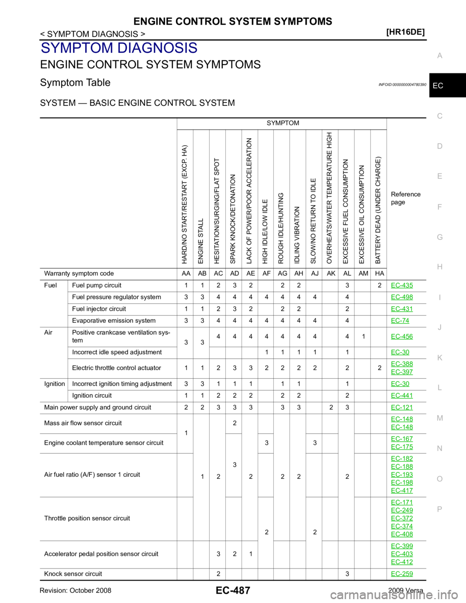
ENGINE CONTROL SYSTEM SYMPTOMS
Symptom Table INFOID:0000000004780390
SYSTEM — BASIC ENGINE CONTROL SYSTEM SYMPTOM
Reference
pageHARD/NO START/RESTART (EXCP. HA)
ENGINE STALL
HESITATION/SURGING/FLAT SPOT
SPARK KNOCK/DETONATION
LACK OF POWER/POOR ACCELERATION
HIGH IDLE/LOW IDLE
ROUGH IDLE/HUNTING
IDLING VIBRATION
SLOW/NO RETURN TO IDLE
OVERHEATS/WATER TEMPERATURE HIGH
EXCESSIVE FUEL CONSUMPTION
EXCESSIVE OIL CONSUMPTION
BATTERY DEAD (UNDER CHARGE)
Warranty symptom code AA AB AC AD AE AF AG AH AJ AK AL AM HA
Fuel Fuel pump circuit 1 1 2 3 2 2 2 3 2 EC-435Fuel pressure regulator system 3 3 4 4 4 4 4 4 4 4
EC-498Fuel injector circuit 1 1 2 3 2 2 2 2
EC-431Evaporative emission system 3 3 4 4 4 4 4 4 4 4
EC-74Air Positive crankcase ventilation sys-
tem 3 34 4 4 4 4 4 4 4 1
EC-456Incorrect idle speed adjustment 1 1 1 1 1
EC-30Electric throttle control actuator 1 1 2 3 3 2 2 2 2 2 2
EC-388 EC-397
Ignition Incorrect ignition timing adjustment 3 3 1 1 1 1 1 1
EC-30Ignition circuit 1 1 2 2 2 2 2 2
EC-441Main power supply and ground circuit 2 2 3 3 3 3 3 2 3
EC-121Mass air flow sensor circuit
1
1 2 2
2 2 2 2 EC-148 EC-148
Engine coolant temperature sensor circuit
33 3
EC-167 EC-175
Air fuel ratio (A/F) sensor 1 circuit
EC-182 EC-188
EC-193
EC-198
EC-417
Throttle position sensor circuit
2 2EC-171 EC-249
EC-372
EC-374
EC-408
Accelerator pedal position sensor circuit 3 2 1
EC-399 EC-403
EC-412
Knock sensor circuit 2 3
EC-259
Page 1844 of 4331

Camshaft position sensor (PHASE) circuit 3 2
EC-268Vehicle speed signal circuit 2 3 3 3
EC-347ECM 2 2 3 3 3 3 3 3 3 3 3
EC-353 EC-355
Intake valve timing control solenoid valve cir-
cuit 3 2 1 3 2 2 3 3
EC-144PNP switch circuit 3 3 3 3 3
EC-362Refrigerant pressure sensor circuit 2 3 3 4
EC-457Electrical load signal circuit 3
EC-428Air conditioner circuit 2 2 3 3 3 3 3 3 3 3 2
MTC-22ABS actuator and electric unit (control unit) 4
BRC-8SYMPTOM
Reference
pageHARD/NO START/RESTART (EXCP. HA)
ENGINE STALL
HESITATION/SURGING/FLAT SPOT
SPARK KNOCK/DETONATION
LACK OF POWER/POOR ACCELERATION
HIGH IDLE/LOW IDLE
ROUGH IDLE/HUNTING
IDLING VIBRATION
SLOW/NO RETURN TO IDLE
OVERHEATS/WATER TEMPERATURE HIGH
EXCESSIVE FUEL CONSUMPTION
EXCESSIVE OIL CONSUMPTION
BATTERY DEAD (UNDER CHARGE)
Warranty symptom code AA AB AC AD AE AF AG AH AJ AK AL AM HA
Page 1855 of 4331

EC
NP
O
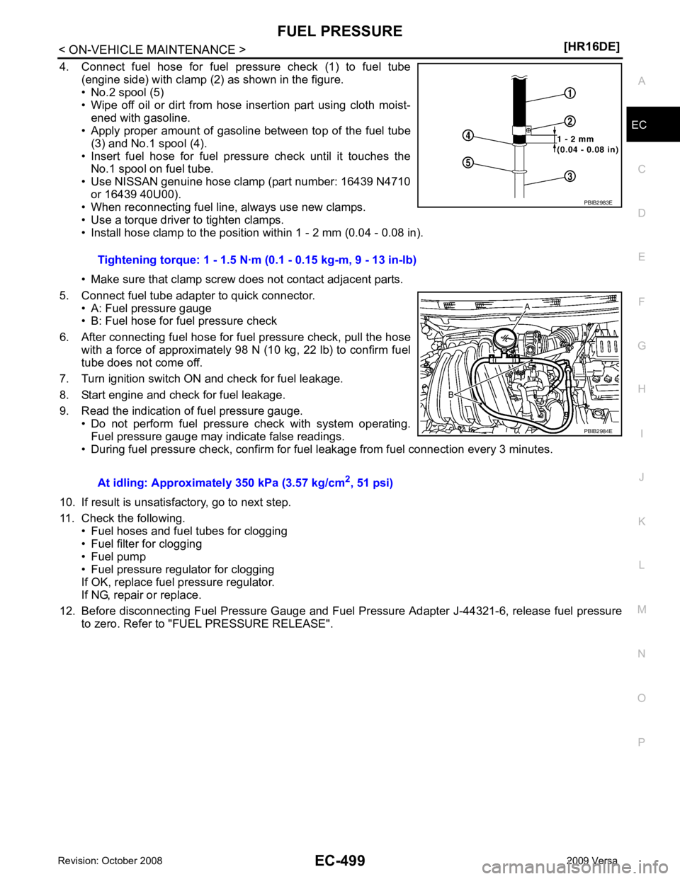
4. Connect fuel hose for fuel pressure check (1) to fuel tube
(engine side) with clamp (2) as shown in the figure.
• No.2 spool (5)
• Wipe off oil or dirt from hose insertion part using cloth moist-
ened with gasoline.
• Apply proper amount of gasoline between top of the fuel tube
(3) and No.1 spool (4).
• Insert fuel hose for fuel pressure check until it touches the No.1 spool on fuel tube.
• Use NISSAN genuine hose clamp (part number: 16439 N4710 or 16439 40U00).
• When reconnecting fuel line, always use new clamps.
• Use a torque driver to tighten clamps.
• Install hose clamp to the positi on within 1 - 2 mm (0.04 - 0.08 in).
• Make sure that clamp screw does not contact adjacent parts.
5. Connect fuel tube adapter to quick connector. • A: Fuel pressure gauge
• B: Fuel hose for fuel pressure check
6. After connecting fuel hose for fuel pressure check, pull the hose with a force of approximately 98 N (10 kg, 22 lb) to confirm fuel
tube does not come off.
7. Turn ignition switch ON and check for fuel leakage.
8. Start engine and check for fuel leakage.
9. Read the indication of fuel pressure gauge. • Do not perform fuel pressure check with system operating.
Fuel pressure gauge may indicate false readings.
• During fuel pressure check, confirm for f uel leakage from fuel connection every 3 minutes.
10. If result is unsatisfactory, go to next step.
11. Check the following. • Fuel hoses and fuel tubes for clogging
• Fuel filter for clogging
• Fuel pump
• Fuel pressure regulator for clogging
If OK, replace fuel pressure regulator.
If NG, repair or replace.
12. Before disconnecting Fuel Pressure Gauge and Fuel Pressure Adapter J-44321-6, release fuel pressure
to zero. Refer to "FUEL PRESSURE RELEASE". Tightening torque: 1 - 1.5 N·m
(0.1 - 0.15 kg-m, 9 - 13 in-lb)
At idling: Approximately 350 kPa (3.57 kg/cm 2
, 51 psi) PBIB2984E
Page 1941 of 4331

EC
NP
O
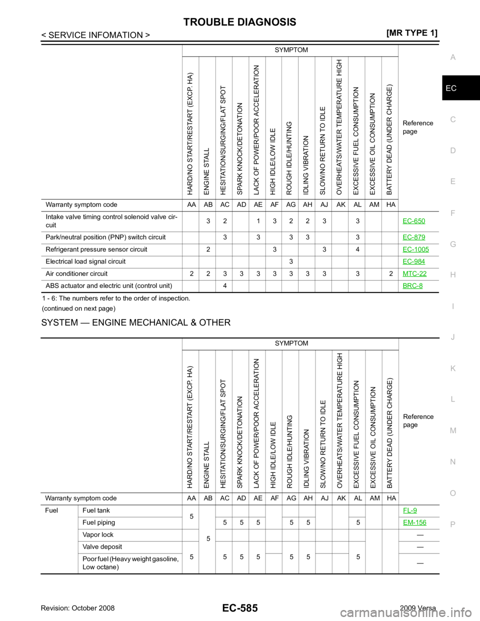
1 - 6: The numbers refer to the order of inspection.
(continued on next page)
SYSTEM — ENGINE MECHANICAL & OTHER Intake valve timing control solenoid valve cir-
cuit 3 2 1 3 2 2 3 3
EC-650Park/neutral position (P
NP) switch circuit 3 3 3 3 3 EC-879Refrigerant pressure sensor circuit 2 3 3 4
EC-1005Electrical load signal circuit 3
EC-984Air conditioner circuit 2 2 3 3 3 3 3 3 3 3 2
MTC-22ABS actuator and electric unit (control unit) 4
BRC-8SYMPTOM
Reference
pageHARD/NO START/RESTART (EXCP. HA)
ENGINE STALL
HESITATION/SURGING/FLAT SPOT
SPARK KNOCK/DETONATION
LACK OF POWER/POOR ACCELERATION
HIGH IDLE/LOW IDLE
ROUGH IDLE/HUNTING
IDLING VIBRATION
SLOW/NO RETURN TO IDLE
OVERHEATS/WATER TEMPERATURE HIGH
EXCESSIVE FUEL CONSUMPTION
EXCESSIVE OIL CONSUMPTION
BATTERY DEAD (UNDER CHARGE)
Warranty symptom code AA AB AC AD AE AF AG AH AJ AK AL AM HA SYMPTOM
Reference
page
HARD/NO START/RESTART (EXCP. HA)
ENGINE STALL
HESITATION/SURGING/FLAT SPOT
SPARK KNOCK/DETONATION
LACK OF POWER/POOR ACCELERATION
HIGH IDLE/LOW IDLE
ROUGH IDLE/HUNTING
IDLING VIBRATION
SLOW/NO RETURN TO IDLE
OVERHEATS/WATER TEMPERATURE HIGH
EXCESSIVE FUEL CONSUMPTION
EXCESSIVE OIL CONSUMPTION
BATTERY DEAD (UNDER CHARGE)
Warranty symptom code AA AB AC AD AE AF AG AH AJ AK AL AM HA
Fuel Fuel tank 5
5 FL-9Fuel piping 5 5 5 5 5 5
EM-156Vapor lock
—
Valve deposit 5 5 5 5 5 5 5 —
Poor fuel (Heavy weight gasoline,
Low octane) —
Page 1977 of 4331

EC
NP
O
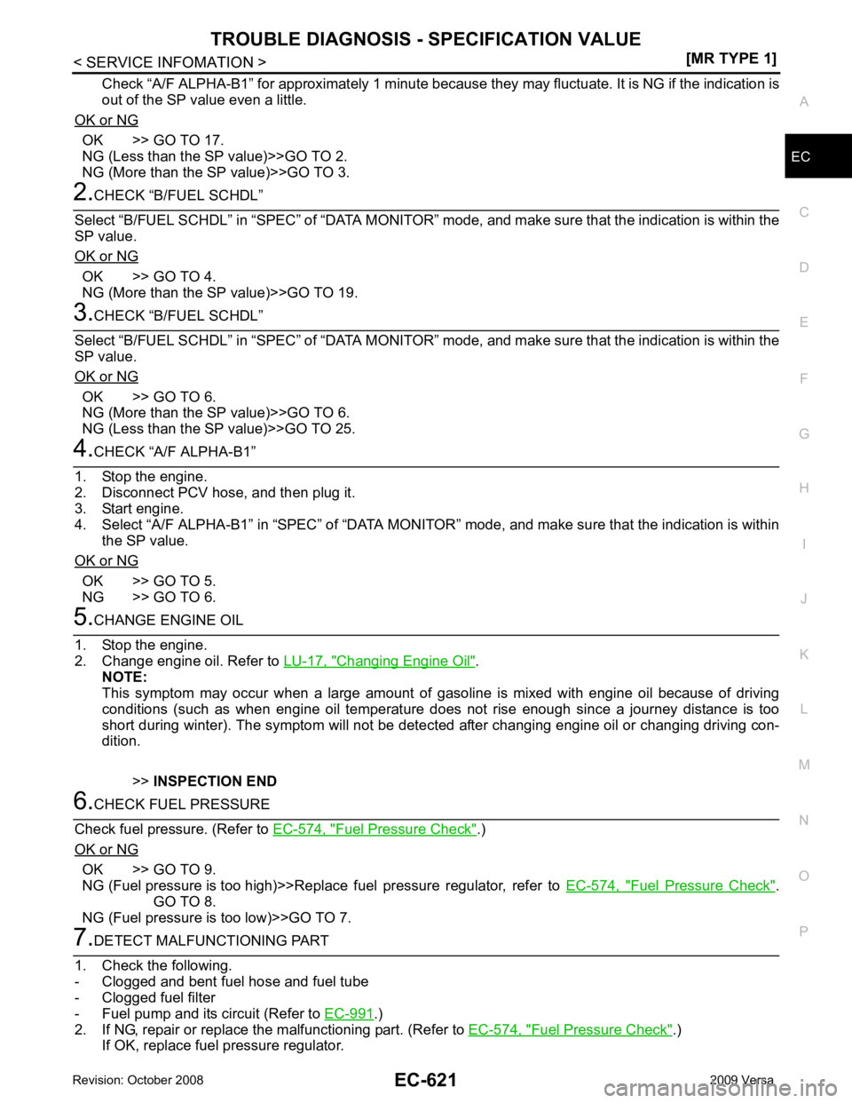
Check “A/F ALPHA-B1” for approximately 1 minute because t
hey may fluctuate. It is NG if the indication is
out of the SP value even a little.
OK or NG OK >> GO TO 17.
NG (Less than the SP value)>>GO TO 2.
NG (More than the SP value)>>GO TO 3. OK >> GO TO 4.
NG (More than the SP value)>>GO TO 19. OK >> GO TO 6.
NG (More than the SP value)>>GO TO 6.
NG (Less than the SP value)>>GO TO 25. OK >> GO TO 5.
NG >> GO TO 6. Changing Engine Oil " .
NOTE:
This symptom may occur when a large amount of gas oline is mixed with engine oil because of driving
conditions (such as when engine oil temperature does not rise enough since a journey distance is too
short during winter). The symptom will not be detect ed after changing engine oil or changing driving con-
dition.
>>INSPECTION END Fuel Pressure Check " .)
OK or NG OK >> GO TO 9.
NG (Fuel pressure is too high)>>Replace fuel pressure regulator, refer to EC-574, " Fuel Pressure Check " .
GO TO 8.
NG (Fuel pressure is too low)>>GO TO 7. .)
2. If NG, repair or replace the malfunctioning part. (Refer to EC-574, " Fuel Pressure Check " .)
If OK, replace fuel pressure regulator.
Page 1994 of 4331
![NISSAN LATIO 2009 Service Repair Manual EC-638< SERVICE INFOMATION >
[MR TYPE 1]
DTC P0011 IVT CONTROL
If 1st trip DTC is detected, go to EC-638, " Diagnosis Procedure " .
WITH GST
Follow the procedure “WITH CONSULT-III” above.
Diagno NISSAN LATIO 2009 Service Repair Manual EC-638< SERVICE INFOMATION >
[MR TYPE 1]
DTC P0011 IVT CONTROL
If 1st trip DTC is detected, go to EC-638, " Diagnosis Procedure " .
WITH GST
Follow the procedure “WITH CONSULT-III” above.
Diagno](/manual-img/5/57359/w960_57359-1993.png)
EC-638< SERVICE INFOMATION >
[MR TYPE 1]
DTC P0011 IVT CONTROL
If 1st trip DTC is detected, go to EC-638, " Diagnosis Procedure " .
WITH GST
Follow the procedure “WITH CONSULT-III” above.
Diagnosis Procedure INFOID:00000000045370851.
CHECK OIL PRESSURE WARNING LAMP
1. Start engine.
2. Check oil pressure warning lamp and confirm it is not illumi-
nated.
OK or NG OK >> GO TO 2.
NG >> Go to LU-16, " Inspection " .
2.
CHECK INTAKE VALVE TIMING CONTROL SOLENOID VALVE
Refer to EC-639, " Component Inspection " .
OK or NG OK >> GO TO 3.
NG >> Replace intake valve timing control solenoid valve. 3.
CHECK CRANKSHAFT POSI TION SENSOR (POS)
Refer to EC-780, " Component Inspection " .
OK or NG OK >> GO TO 4.
NG >> Replace crankshaft position sensor (POS). 4.
CHECK CAMSHAFT POSITION SENSOR (PHASE)
Refer to EC-785, " Component Inspection " .
OK or NG OK >> GO TO 5.
NG >> Replace camshaft position sensor (PHASE). 5.
CHECK CAMSHAFT (INTAKE)
Check the following.
• Accumulation of debris to the si gnal plate of camshaft (1) rear end
• Chipping signal plate of camshaft rear end
OK or NG OK >> GO TO 6.
NG >> Remove debris and clean the signal plate of camshaft rear end or replace camshaft. 6.
CHECK TIMING CHAIN INSTALLATION
Check service records for any recent repairs that may cause timing chain misaligned.
Are there any service records that may cause timing chain misaligned?
Yes or No Yes >> Check timing chain installation. Refer to
EM-160 .
No >> GO TO 7. PBIA8559J
PBIA9557J