2009 NISSAN LATIO low oil pressure
[x] Cancel search: low oil pressurePage 2882 of 4331
![NISSAN LATIO 2009 Service Repair Manual EC-1526< SERVICE INFOMATION >
[MR TYPE 2]
IGNITION SIGNAL
7. Remove fuel pump fuse (1) in IPDM E/R (2) to release fuel pres- sure.
NOTE:
Do not use CONSULT-III to releas e fuel pressure, or f NISSAN LATIO 2009 Service Repair Manual EC-1526< SERVICE INFOMATION >
[MR TYPE 2]
IGNITION SIGNAL
7. Remove fuel pump fuse (1) in IPDM E/R (2) to release fuel pres- sure.
NOTE:
Do not use CONSULT-III to releas e fuel pressure, or f](/manual-img/5/57359/w960_57359-2881.png)
EC-1526< SERVICE INFOMATION >
[MR TYPE 2]
IGNITION SIGNAL
7. Remove fuel pump fuse (1) in IPDM E/R (2) to release fuel pres- sure.
NOTE:
Do not use CONSULT-III to releas e fuel pressure, or fuel pres-
sure applies again during the following procedure.
- : Vehicle front
8. Start engine.
9. After engine stalls, crank it two or three times to release all fuel
pressure.
10. Turn ignition switch OFF.
11. Remove all ignition coil harness connectors to avoid the electri-
cal discharge from the ignition coils.
12. Remove ignition coil and spark plug of the cylinder to be checked.
13. Crank engine for 5 seconds or more to remove combustion gas in the cylinder.
14. Connect spark plug and harness connector to ignition coil.
15. Fix ignition coil using a rope etc. with gap of 13 - 17 mm (0.52 - 0.66 in) between the edge of the spark plug and grounded metal
portion as shown in the figure.
16. Crank engine for about 3 seconds, and check whether spark is generated between the spark plug and the grounded metal por-
tion.
CAUTION:
• Do not approach to the spar k plug and the ignition coil
within 50cm. Be careful not to get an electrical shock
while checking, because the el ectrical discharge voltage
becomes 20kV or more.
• It might cause to damage the igni tion coil if the gap of more than 17 mm (0.66 in) is taken.
NOTE:
When the gap is less than 13 mm (0.52 in), the sp ark might be generated even if the coil is mal-
functioning.
17. If NG, replace ignition coil with power transistor.
CONDENSER-2
1. Turn ignition switch OFF.
2. Disconnect condenser-2 harness connector.
3. Check resistance between condenser-2 terminals 1 and 2.
4. If NG, replace condenser-2.
Removal and Installation INFOID:0000000004500425
IGNITION COIL WITH POWER TRANSISTOR
Refer to EM-153 .
Spark should be generated. PBIB2958E
PBIB2325E
Resistance: Above 1 M
Ω [at 25 °C (77 °F)] PBIB0794E
Page 2948 of 4331
EM
N
O P
CONTENTS
ENGINE MECHANICAL
HR16DE
PRECAUTION ....... ........................................
4
PRECAUTIONS .............................................. .....4
Precaution for Supplemental Restraint System
(SRS) "AIR BAG" and "SEAT BELT PRE-TEN-
SIONER" ............................................................. ......
4
Precaution Necessary fo r Steering Wheel Rota-
tion After Battery Disconnect ............................... ......
4
Precaution for Procedure without Cowl Top Cover ......5
Precaution for Drain Cool ant .....................................5
Precaution for Disconnecting Fuel Piping ........... ......5
Precaution for Removal and Disassembly ................5
Precaution for Inspection, Repair and Replace-
ment .................................................................... ......
5
Precaution for Assembly and Installation ..................5
Parts Requiring Angular Tightening ..........................6
Precaution for Liquid Gasket ............................... ......6
PREPARATION .... ........................................8
PREPARATION .............................................. .....8
Special Service Tools .......................................... ......8
Commercial Service Tools .................................. ......9
SYMPTOM DIAGNOSIS ..... .........................12
NOISE, VIBRATION AND HARSHNESS
(NVH) TROUBLESHOOTING ........................ ....
12
NVH Troubleshooting - Engine Noise ................. ....12
Use the Chart Below to Help You Find the Cause
of the Symptom ................................................... ....
13
ON-VEHICLE MAINTENA NCE ....................14
DRIVE BELTS ................................................ ....14
Checking ............................................................. ....14
Tension Adjustment ............................................ ....14
Removal and Installation .........................................15
AIR CLEANER FILTER .................................. ....17 Removal and Installation .....................................
....17
SPARK PLUG ................................................... 18
Exploded View ..................................................... ....18
Removal and Installation ..................................... ....18
CAMSHAFT VALVE CLEARANCE .................. 20
Inspection and Adjustment .................................. ....20
COMPRESSION PRESSURE ........................... 23
Inspection ............................................................ ....23
ON-VEHICLE REPAIR ..... ............................24
DRIVE BELT IDLER PULLEY .......................... 24
Exploded View ..................................................... ....24
Removal and Installation ..................................... ....24
AIR CLEANER AND AIR DUCT ....................... 26
Exploded View ..................................................... ....26
Removal and Installation ..................................... ....26
Inspection ............................................................ ....27
INTAKE MANIFOLD ......................................... 28
Exploded View ..................................................... ....28
Removal and Installation ..................................... ....28
EXHAUST MANIFOLD ...................................... 31
Exploded View ..................................................... ....31
Removal and Installation ..................................... ....31
FUEL INJECTOR AND FUEL TUBE ................ 34
Exploded View ..................................................... ....34
Removal and Installation ..................................... ....34
Inspection ............................................................ ....38
OIL PAN (LOWER) ........................................... 39
Exploded View ..................................................... ....39
Removal and Installation ..................................... ....39
Inspection ............................................................ ....41
OIL PAN (UPPER) AND OIL STRAINER ......... 42
Component .......................................................... ....42
Page 2952 of 4331
![NISSAN LATIO 2009 Service Repair Manual PRECAUTIONS
EM-5
< PRECAUTION >
[HR16DE] C
D E
F
G H
I
J
K L
M A EM
NP
O
5. When the repair work is completed, return the ignition switch to the
″LOCK ″ position before connecting
t NISSAN LATIO 2009 Service Repair Manual PRECAUTIONS
EM-5
< PRECAUTION >
[HR16DE] C
D E
F
G H
I
J
K L
M A EM
NP
O
5. When the repair work is completed, return the ignition switch to the
″LOCK ″ position before connecting
t](/manual-img/5/57359/w960_57359-2951.png)
PRECAUTIONS
EM-5
< PRECAUTION >
[HR16DE] C
D E
F
G H
I
J
K L
M A EM
NP
O
5. When the repair work is completed, return the ignition switch to the
″LOCK ″ position before connecting
the battery cables. (At this time, the steering lock mechanism will engage.)
6. Perform a self-diagnosis check of al l control units using CONSULT-III.
Precaution for Procedur e without Cowl Top Cover INFOID:0000000004784258
When performing the procedure after removing cowl top cover, cover
the lower end of windshield.
Precaution for Drain Coolant INFOID:0000000004784260
• Drain coolant when engine is cooled.
Precaution for Disco nnecting Fuel Piping INFOID:0000000004784261
• Before starting work, make sure no fire or spark producing items are in the work area.
• Release fuel pressure before disassembly.
• After disconnecting pipes, plug openings to stop fuel leakage.
Precaution for Removal and Disassembly INFOID:0000000004784262
• When instructed to use special service tools, use the spec ified tools. Always be careful to work safely, avoid
forceful or uninstructed operations.
• Exercise maximum care to avoid damage to mating or sliding surfaces.
• Cover openings of engine system with tape or the equiva lent, if necessary, to seal out foreign materials.
• Mark and arrange disassembly parts in an organized way for easy troubleshooting and assembly.
• When loosening nuts and bolts, as a basic rule, start with the one furthest outside, then the one diagonally opposite, and so on. If the order of loosening is specif ied, do exactly as specified. Power tools may be used
where noted in the step.
Precaution for Inspection, Repair and Replacement INFOID:0000000004784263
• Before repairing or replacing, thoroughly inspect parts. Inspect new replacement parts in the same way, and
replace if necessary.
Precaution for Assembly and Installation INFOID:0000000004784264
• Use torque wrench to tighten bolts or nuts to specification.
• When tightening nuts and bolts, as a basic rule, equally tighten in several different steps starting with the ones in center, then ones on inside and outside diagonally in this order. If the order of tightening is specified,
do exactly as specified.
• Replace with new gasket, packing, oil seal or O-ring.
• Thoroughly wash, clean, and air-blow each part. Carefully check oil or coolant passages for any restriction
and blockage.
• Avoid damaging sliding or mating surfaces. Completely remove foreign materials such as cloth lint or dust. Before assembly, oil sliding surfaces well.
• Release air within route after draining coolant.
• Before starting engine, apply fuel pressure to fuel lines with turning ignition switch ON (with engine stopped). Then make sure that there are no leaks at fuel line connections.
• After repairing, start engine and increase engine speed to check coolant, fuel, oil, and exhaust systems for leakage. PIIB3706J
Page 2970 of 4331
EM
NP
O
COMPRESSION PRESSURE
Inspection INFOID:0000000004784276
1. Warm up engine thoroughly. Then, stop it.
2. Release fuel pressure. Refer to EC-498, " Inspection " .
3. Remove ignition coil and spark plug from each cylinder. Refer to EM-46, " Exploded View " .
4. Connect an engine tachometer (not required in use of CONSULT-III).
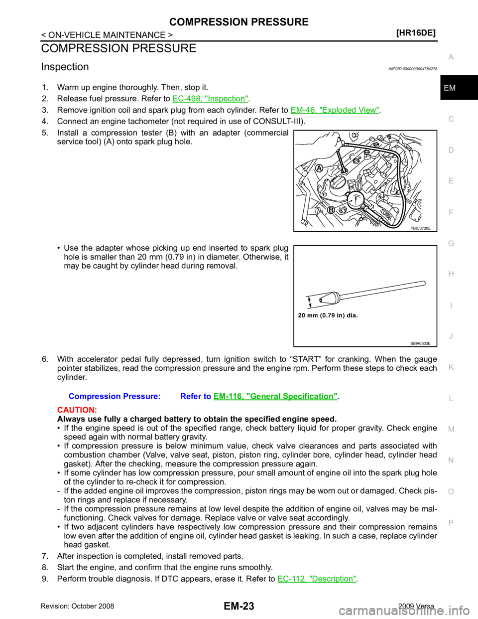
5. Install a compression tester (B) with an adapter (commercial service tool) (A) onto spark plug hole.
• Use the adapter whose picking up end inserted to spark plug hole is smaller than 20 mm (0.79 in) in diameter. Otherwise, it
may be caught by cylinder head during removal.
6. With accelerator pedal fully depressed, turn ignition switch to “START” for cranking. When the gauge pointer stabilizes, read the compression pressure and the engine rpm. Perform these steps to check each
cylinder.
CAUTION:
Always use fully a charged battery to obtain the specified engine speed.
• If the engine speed is out of the specified range, c heck battery liquid for proper gravity. Check engine
speed again with normal battery gravity.
• If compression pressure is below minimum value, check valve clearances and parts associated with combustion chamber (Valve, valve seat, piston, pi ston ring, cylinder bore, cylinder head, cylinder head
gasket). After the checking, measure the compression pressure again.
• If some cylinder has low compression pressure, pour small amount of engine oil into the spark plug hole
of the cylinder to re-check it for compression.
- If the added engine oil improves the compression, piston rings may be worn out or damaged. Check pis-
ton rings and replace if necessary.
- If the compression pressure remains at low level despite the addition of engine oil, valves may be mal- functioning. Check valves for damage. Replace valve or valve seat accordingly.
• If two adjacent cylinders have respectively low compression pressure and their compression remains low even after the addition of engine oil, cylinder head gasket is leaking. In such a case, replace cylinder
head gasket.
7. After inspection is completed, install removed parts.
8. Start the engine, and confirm that the engine runs smoothly.
9. Perform trouble diagnosis. If DTC appears, erase it. Refer to EC-112, " Description " . SBIA0533E
General Specification " .
Page 3004 of 4331
EM
NP
O
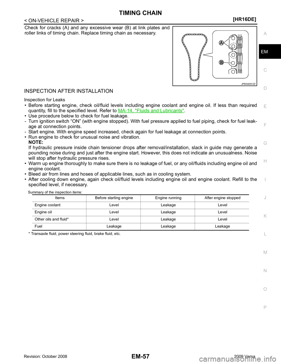
Check for cracks (A) and any excessive wear (B) at link plates and
roller links of timing chain. Replace timing chain as necessary.
INSPECTION AFTER INSTALLATION
Inspection for Leaks • Before starting engine, check oil/fluid levels incl uding engine coolant and engine oil. If less than required
quantity, fill to the specified level. Refer to MA-14, " Fluids and Lubricants " .
• Use procedure below to check for fuel leakage.
- Turn ignition switch “ON” (with engine stopped). With fuel pressure applied to fuel piping, check for fuel leak-
age at connection points.
- Start engine. With engine speed increased, check again for fuel leakage at connection points.
• Run engine to check for unusual noise and vibration. NOTE:
If hydraulic pressure inside chain tensioner drops after removal/installation, slack in guide may generate a
pounding noise during and just after the engine start. However, this does not indicate an unusualness. Noise
will stop after hydraulic pressure rises.
• Warm up engine thoroughly to make sure there is no leak age of fuel, or any oil/fluids including engine oil and
engine coolant.
• Bleed air from lines and hoses of applicable lines, such as in cooling system.
• After cooling down engine, again check oil/fluid levels including engine oil and engine coolant. Refill to the specified level, if necessary.
Summary of the inspection items:
* Transaxle fluid, power steering fluid, brake fluid, etc.
Page 3008 of 4331
EM
NP
O
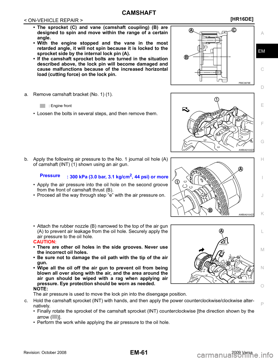
• The sprocket (C) and vane (camshaft coupling) (B) are
designed to spin and move wi thin the range of a certain
angle.
• With the engine stopped and the vane in the most
retarded angle, it will not sp in because it is locked to the
sprocket side by the internal lock pin (A).
• If the camshaft sprocket bolts are turned in the situation
described above, the lock pi n will become damaged and
cause malfunctions because of the increased horizontal
load (cutting force) on the lock pin.
a. Remove camshaft bracket (No. 1) (1). • Loosen the bolts in several steps, and then remove them.
b. Apply the following air pressure to the No. 1 journal oil hole (A) of camshaft (INT) (1) shown using an air gun.
• Apply the air pressure into the oil hole on the second groove from the front of camshaft thrust (B).
• Proceed all the way through step “e” with the air pressure on.
• Attach the rubber nozzle (B) narrowed to the top of the air gun (A) to prevent air leakage from the oil hole. Securely apply the
air pressure to the oil hole.
CAUTION:
• There are other oil holes in the side grooves. Never use
the incorrect oil holes.
• Be sure not to damage the oil path with the tip of the air
gun.
• Wipe all the oil off the air gun to prevent oil from being blown all over along with the air, and the area around the
air gun should be wiped wi th a rag when applying air
pressure. Eye protection should be worn as needed.
NOTE:
The air pressure is used to move the lock pin into the disengage position.
c. Hold the camshaft sprocket (INT) with hands, and then apply the power counterclockwise/clockwise alter-
natively.
• Finally rotate the sprocket of the camshaft sprocke t (INT) counterclockwise [the direction shown by the
arrow ( )].
• Perform the work while applying the air pressure to the oil hole. AWBIA0105ZZ
Page 3021 of 4331
Fluids and Lubricants " .
• Use procedure below to check for fuel leakage.
- Turn ignition switch “ON” (with engine stopped). With fuel pressure applied to fuel piping, check for fuel leak-
age at connection points.
- Start engine. With engine speed increased, che ck again for fuel leakage at connection points.
• Run engine to check for unusual noise and vibration. NOTE:
If hydraulic pressure inside timing chain tensioner drops after removal/installation, slack in the guide may
generate a pounding noise during and just after engine start. However, this is normal. Noise will stop after
hydraulic pressure rises.
• Warm up engine thoroughly to make sure there is no leakage of fuel, or any oil/fluids including engine oil and
engine coolant.
• Bleed air from lines and hoses of applicable lines, such as in cooling system.
• After cooling down engine, again check oil/fluid levels including engine oil and engine coolant. Refill to the
specified level, if necessary.
Summary of the inspection items:
*: Transmission/transaxle/CVT fluid, power steering fluid, brake fluid, etc.
Inspection of Camshaft Sprocket (INT) Oil Groove
CAUTION:
• Perform this inspection only when DTC P0011 is de tected in self-diagnostic results of CONSULT-III
and it is directed according to inspect ion procedure of EC section. Refer to EC-133, " Diagnosis Pro-
cedure " .
• Check when engine is cold so as to pr event burns from the splashing engine oil.
1. Check engine oil level. Refer to LU-7, " Inspection " .
2. Perform the following procedure so as to prevent the engine from being unintentionally started while
checking.
a. Release the fuel pressure. Refer to EC-498, " Inspection " .
b. Remove intake manifold. Refer to EM-28, " Exploded View " .
c. Disconnect ignition coil and injector harness connectors. Refer to EM-46, " Exploded View " .
3. Remove intake valve timing control solenoid valve. Refer to EM-49, " Exploded View " .
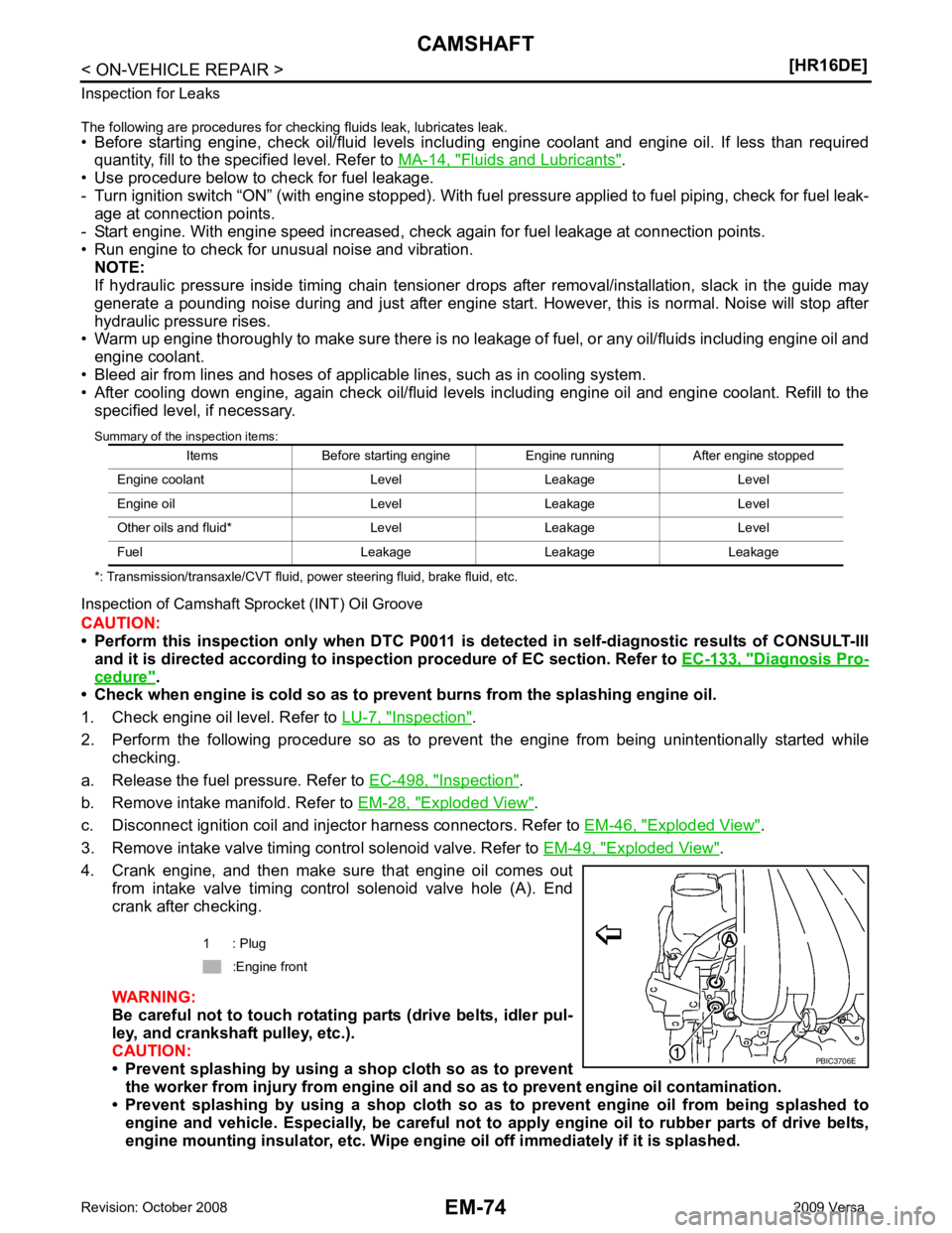
4. Crank engine, and then make sure that engine oil comes out from intake valve timing control solenoid valve hole (A). End
crank after checking.
WARNING:
Be careful not to touch rotating parts (drive belts, idler pul-
ley, and crankshaft pulley, etc.).
CAUTION:
• Prevent splashing by using a shop cloth so as to prevent
the worker from injury from engine oil an d so as to prevent engine oil contamination.
• Prevent splashing by using a shop cloth so as to prevent engine oil from being splashed to
engine and vehicle. Especially, be careful not to apply engine oil to rubber parts of drive belts,
engine mounting insulator, etc. Wipe engi ne oil off immediately if it is splashed.
Items Before starting engine Engine running After engine stopped
Engine coolant Level Leakage Level
Engine oil Level Leakage Level
Other oils and fluid* Level Leakage Level
Fuel Leakage Leakage Leakage 1 : Plug
:Engine front
Page 3026 of 4331
EM
NP
O
CYLINDER HEAD
Removal and Installation INFOID:0000000004784305
REMOVAL WARNING:
• Put a “CAUTION: FLAMMABLE” sign in the workshop.
• Be sure to work in a well ventila ted area and furnish workshop with a CO
2 fire extinguisher.
• Do not smoke while servicing fuel system. Keep open flames and sparks away from the work area.
1. Release fuel pressure. Refer to EC-498, " Inspection " .
2. Drain engine coolant and engine oil. Refer to CO-11, " Changing Engine Coolant " and
LU-8, " Draining " .
CAUTION:
• Perform this step when the engine is cold.
• Never spill engine coolant an d engine oil on drive belt.
3. Remove the following components and related parts. • Front fender protector (RH): Refer to EI-24, " Removal and Installation " .
• Generator: Refer to SC-25, " Removal and Installation " .
• Exhaust front tube: Refer to EX-5, " Component " .
• Exhaust manifold: Refer to EM-31, " Exploded View " .
• Intake manifold: Refer to EM-28, " Exploded View " .
• Fuel tube and fuel injector: Refer to EM-34, " Exploded View " .
• Water outlet: Refer to CO-24, " Removal and Installation " .
• Drive belt: Refer to EM-15, " Removal and Installation " .
• Front cover: Refer to EM-49, " Exploded View " .
• Camshaft: Refer to EM-58, " Exploded View " .
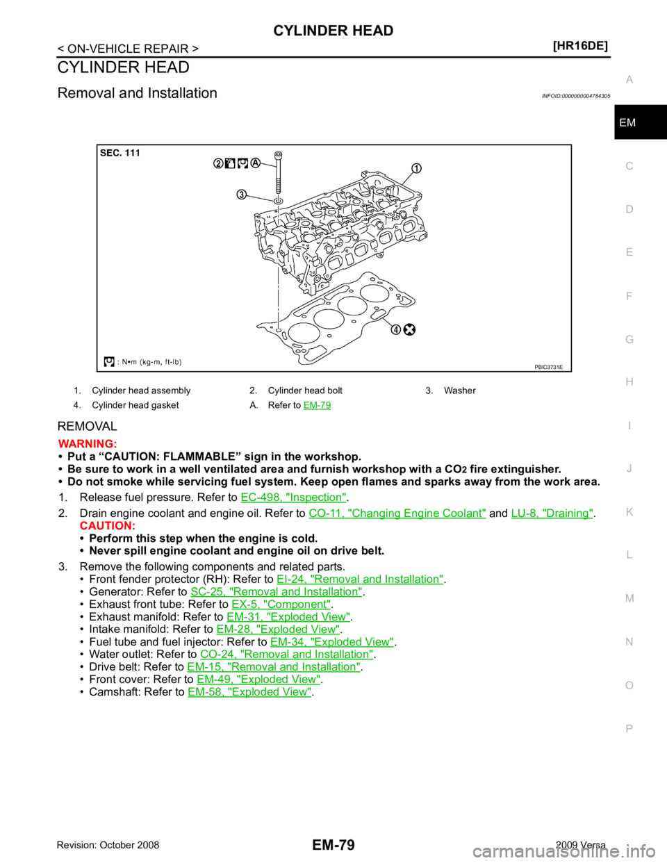
1. Cylinder head assembly 2. Cylinder head bolt 3. Washer
4. Cylinder head gasket A. Refer to EM-79