2009 NISSAN LATIO low oil pressure
[x] Cancel search: low oil pressurePage 3038 of 4331

EM
NP
O
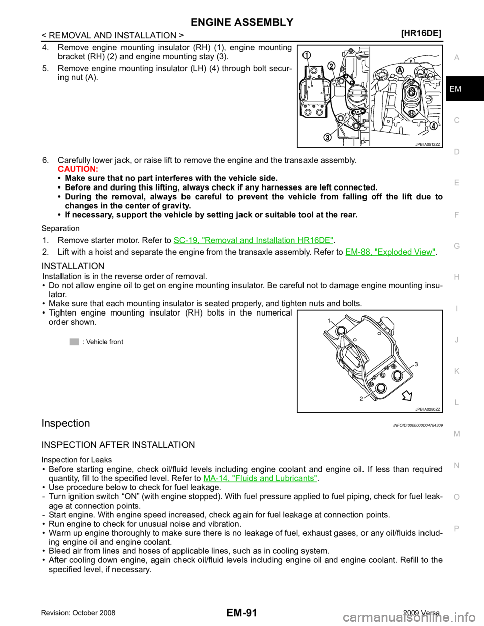
4. Remove engine mounting insulator (RH) (1), engine mounting
bracket (RH) (2) and engine mounting stay (3).
5. Remove engine mounting insulator (LH) (4) through bolt secur- ing nut (A).
6. Carefully lower jack, or raise lift to remove the engine and the transaxle assembly. CAUTION:
• Make sure that no part interferes with the vehicle side.
• Before and during this lifting, alw ays check if any harnesses are left connected.
• During the removal, always be careful to prevent the vehicle from falling off the lift due to
changes in the center of gravity.
• If necessary, support the vehicle by setting jack or suitable tool at the rear.
Separation 1. Remove starter motor. Refer to SC-19, " Removal and Installation HR16DE " .
2. Lift with a hoist and separate the engine from the transaxle assembly. Refer to EM-88, " Exploded View " .
INSTALLATION Installation is in the reverse order of removal.
• Do not allow engine oil to get on engine mounting insulator. Be careful not to damage engine mounting insu- lator.
• Make sure that each mounting insulator is seated properly, and tighten nuts and bolts.
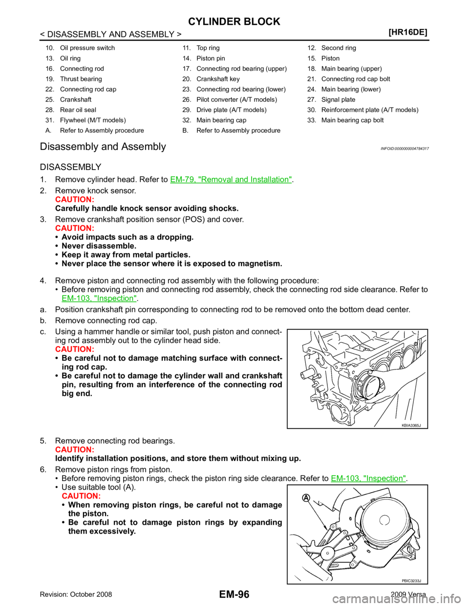
• Tighten engine mounting insulator (RH) bolts in the numerical
order shown.
Inspection INFOID:0000000004784309
INSPECTION AFTER INSTALLATION
Inspection for Leaks • Before starting engine, check oil/fluid levels incl uding engine coolant and engine oil. If less than required
quantity, fill to the specified level. Refer to MA-14, " Fluids and Lubricants " .
• Use procedure below to check for fuel leakage.
- Turn ignition switch “ON” (with engine stopped). With fuel pressure applied to fuel piping, check for fuel leak-
age at connection points.
- Start engine. With engine speed increased, check again for fuel leakage at connection points.
• Run engine to check for unusual noise and vibration.
• Warm up engine thoroughly to make sure there is no leak age of fuel, exhaust gases, or any oil/fluids includ-
ing engine oil and engine coolant.
• Bleed air from lines and hoses of applicable lines, such as in cooling system.
• After cooling down engine, again check oil/fluid levels including engine oil and engine coolant. Refill to the specified level, if necessary.
Page 3043 of 4331

Removal and Installation " .
2. Remove knock sensor. CAUTION:
Carefully handle knock sensor avoiding shocks.
3. Remove crankshaft position sensor (POS) and cover. CAUTION:
• Avoid impacts such as a dropping.
• Never disassemble.
• Keep it away from metal particles.
• Never place the sensor where it is exposed to magnetism.
4. Remove piston and connecting rod assembly with the following procedure: • Before removing piston and connecting rod assembly, check the connecting rod side clearance. Refer to
EM-103, " Inspection " .
a. Position crankshaft pin corresponding to connecting rod to be removed onto the bottom dead center.
b. Remove connecting rod cap.
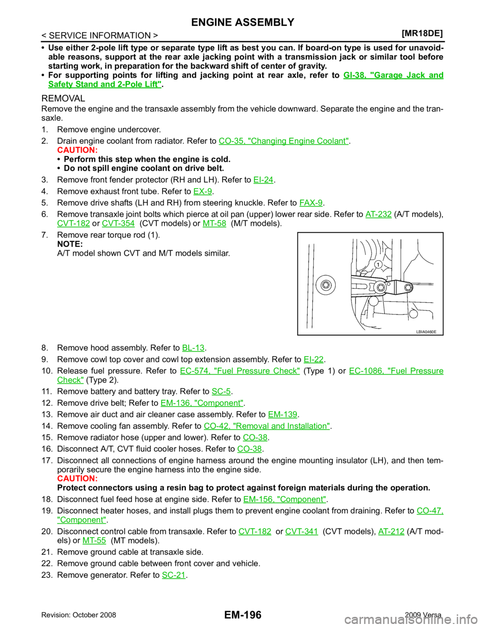
c. Using a hammer handle or similar tool, push piston and connect- ing rod assembly out to the cylinder head side.
CAUTION:
• Be careful not to damage matching surface with connect-
ing rod cap.
• Be careful not to damage the cylinder wall and crankshaft pin, resulting from an inte rference of the connecting rod
big end.
5. Remove connecting rod bearings. CAUTION:
Identify installation positions, and store them without mixing up.
6. Remove piston rings from piston. • Before removing piston rings, check the piston ring side clearance. Refer to EM-103, " Inspection " .
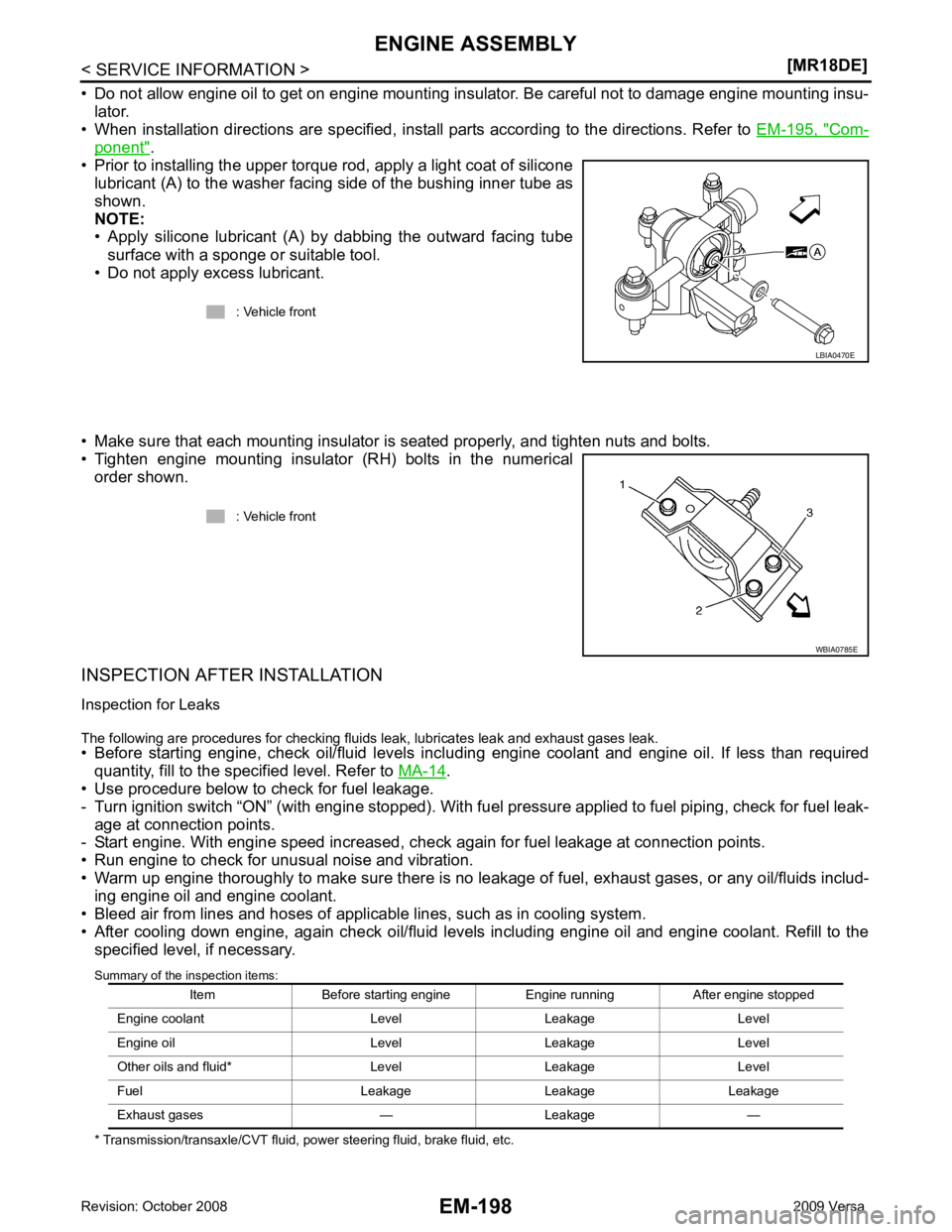
• Use suitable tool (A).
CAUTION:
• When removing piston rings, be careful not to damage the piston.
• Be careful not to damage piston rings by expanding
them excessively.
10. Oil pressure switch 11. Top ring 12. Second ring
13. Oil ring 14. Piston pin 15. Piston
16. Connecting rod 17. Connecting rod bearing (upper) 18. Main bearing (upper)
19. Thrust bearing 20. Crankshaft key 21. Connecting rod cap bolt
22. Connecting rod cap 23. Connecting rod bearing (lower) 24. Main bearing (lower)
25. Crankshaft 26. Pilot converter (A/T models) 27. Signal plate
28. Rear oil seal 29. Drive plate (A/T models) 30. Reinforcement plate (A/T models)
31. Flywheel (M/T models) 32. Main bearing cap 33. Main bearing cap bolt
A. Refer to Assembly procedure B. Refer to Assembly procedure PBIC3233J
Page 3074 of 4331
![NISSAN LATIO 2009 Service Repair Manual PRECAUTIONS
EM-127
< SERVICE INFORMATION >
[MR18DE] C
D E
F
G H
I
J
K L
M A EM
NP
O
5. When the repair work is completed, return the ignition switch to the
″LOCK ″ position before c NISSAN LATIO 2009 Service Repair Manual PRECAUTIONS
EM-127
< SERVICE INFORMATION >
[MR18DE] C
D E
F
G H
I
J
K L
M A EM
NP
O
5. When the repair work is completed, return the ignition switch to the
″LOCK ″ position before c](/manual-img/5/57359/w960_57359-3073.png)
PRECAUTIONS
EM-127
< SERVICE INFORMATION >
[MR18DE] C
D E
F
G H
I
J
K L
M A EM
NP
O
5. When the repair work is completed, return the ignition switch to the
″LOCK ″ position before connecting
the battery cables. (At this time, the steering lock mechanism will engage.)
6. Perform a self-diagnosis check of al l control units using CONSULT-III.
Precaution for Procedur e without Cowl Top Cover INFOID:0000000004307110
When performing the procedure after removing cowl top cover, cover
the lower end of windshield.
Precaution for Drain Coolant INFOID:0000000004307112
• Drain coolant when engine is cooled.
Precaution for Disco nnecting Fuel Piping INFOID:0000000004307113
• Before starting work, make sure no fire or spark producing items are in the work area.
• Release fuel pressure before disassembly.
• After disconnecting pipes, plug openings to stop fuel leakage.
Precaution for Removal and Disassembly INFOID:0000000004307114
• When instructed to use special service tools, use the spec ified tools. Always be careful to work safely, avoid
forceful or uninstructed operations.
• Exercise maximum care to avoid damage to mating or sliding surfaces.
• Cover openings of engine system with tape or the equiva lent, if necessary, to seal out foreign materials.
• Mark and arrange disassembly parts in an organized way for easy troubleshooting and assembly.
• When loosening nuts and bolts, as a basic rule, start with the one furthest outside, then the one diagonally opposite, and so on. If the order of loosening is specif ied, do exactly as specified. Power tools may be used
where noted in the step.
Precaution for Inspection, Repair and Replacement INFOID:0000000004307115
• Before repairing or replacing, thoroughly inspect parts. Inspect new replacement parts in the same way, and
replace if necessary.
Precaution for Assembly and Installation INFOID:0000000004307116
• Use torque wrench to tighten bolts or nuts to specification.
• When tightening nuts and bolts, as a basic rule, equally tighten in several different steps starting with the ones in center, then ones on inside and outside diagonally in this order. If the order of tightening is specified,
do exactly as specified.
• Replace with new gasket, packing, oil seal or O-ring.
• Thoroughly wash, clean, and air-blow each part. Carefully check oil or coolant passages for any restriction
and blockage.
• Avoid damaging sliding or mating surfaces. Completely remove foreign materials such as cloth lint or dust. Before assembly, oil sliding surfaces well.
• Release air within route after draining coolant.
• Before starting engine, apply fuel pressure to fuel lines with turning ignition switch ON (with engine stopped). Then make sure that there are no leaks at fuel line connections.
• After repairing, start engine and increase engine speed to check coolant, fuel, oil, and exhaust systems for leakage. PIIB3706J
Page 3124 of 4331
![NISSAN LATIO 2009 Service Repair Manual CAMSHAFT
EM-177
< SERVICE INFORMATION >
[MR18DE] C
D E
F
G H
I
J
K L
M A EM
NP
O
10. Install camshaft sprocket (EXH) (2).
NOTE:
Secure the hexagonal part (A) of camshaft (EXH) using wrench
to tighten NISSAN LATIO 2009 Service Repair Manual CAMSHAFT
EM-177
< SERVICE INFORMATION >
[MR18DE] C
D E
F
G H
I
J
K L
M A EM
NP
O
10. Install camshaft sprocket (EXH) (2).
NOTE:
Secure the hexagonal part (A) of camshaft (EXH) using wrench
to tighten](/manual-img/5/57359/w960_57359-3123.png)
CAMSHAFT
EM-177
< SERVICE INFORMATION >
[MR18DE] C
D E
F
G H
I
J
K L
M A EM
NP
O
10. Install camshaft sprocket (EXH) (2).
NOTE:
Secure the hexagonal part (A) of camshaft (EXH) using wrench
to tighten bolt.
11. Install timing chain and related parts. Refer to EM-160 .
12. Inspect and adjust valve clearance. Refer to EM-178, " Valve Clearance " .
13. Installation of the remaining components is in the reverse order of removal.
INSPECTION AFTER INSTALLATION The following are procedures for chec king fluids leak, lubricates leak.
• Before starting engine, check oil/fluid levels incl uding engine coolant and engine oil. If less than required
quantity, fill to the specified level. Refer to GI-42, " Recommended Chemical Product and Sealant " .
• Use procedure below to check for fuel leakage.
- Turn ignition switch “ON” (with engine stopped). With fuel pressure applied to fuel piping, check for fuel leak-
age at connection points.
- Start engine. With engine speed increased, check again for fuel leakage at connection points.
• Run engine to check for unusual noise and vibration. NOTE:
If hydraulic pressure inside timing chain tensioner drops after removal/installation, slack in the guide may
generate a pounding noise during and just after engine start. However, this is normal. Noise will stop after
hydraulic pressure rises.
• Warm up engine thoroughly to make sure there is no leak age of fuel, or any oil/fluids including engine oil and
engine coolant.
• Bleed air from lines and hoses of applicable lines, such as in cooling system.
• After cooling down engine, again check oil/fluid levels including engine oil and engine coolant. Refill to the
specified level, if necessary.
Summary of the inspection items:
* Transmission/transaxle/CVT fluid, power steering fluid, brake fluid, etc.
Inspection of Camshaft Sprocket (INT) Oil Groove
CAUTION:
• Perform this inspection only when DTC P0011 is detected in self-diagnostic results of CONSULT-III
and it is directed according to inspect ion procedure of EC section. Refer to EC-638, " Diagnosis Pro-
cedure " (Type 1) or
EC-1153, " Diagnosis Procedure " (Type 2).
• Check when engine is cold so as to pr event burns from the splashing engine oil.
1. Check engine oil level. Refer to LU-16, " Inspection " .
2. Perform the following procedure so as to prevent the engine from being unintentionally started while checking.
a. Remove intake manifold. Refer to EM-141, " Component " .
b. Disconnect ignition coil and in jector harness connectors.
3. Remove intake valve timing control solenoid valve. Refer to EM-160, " Component " .
1 : Camshaft sprocket (INT)
Camshaft sprocket
bolt (EXH) : 88.2 N·m (9.0 kg-m, 65 ft-lb) PBIC3454J
Item Before starting engine Engine running After engine stopped
Engine coolant Level Leakage Level
Engine oil Level Leakage Level
Other oils and fluid* Level Leakage Level
Fuel Leakage Leakage Leakage
Exhaust gases — Leakage —
Page 3143 of 4331

Garage Jack and
Safety Stand and 2-Pole Lift " .
REMOVAL
Remove the engine and the transaxle assembly from t he vehicle downward. Separate the engine and the tran-
saxle.
1. Remove engine undercover.
2. Drain engine coolant from radiator. Refer to CO-35, " Changing Engine Coolant " .
CAUTION:
• Perform this step when the engine is cold.
• Do not spill engine coolant on drive belt.
3. Remove front fender protector (RH and LH). Refer to EI-24 .
4. Remove exhaust front tube. Refer to EX-9 .
5. Remove drive shafts (LH and RH) from steering knuckle. Refer to FAX-9 .
6. Remove transaxle joint bolts which pierce at oil pan (upper) lower rear side. Refer to AT-232 (A/T models),
CVT-182 or
CVT-354 (CVT models) or
MT-58 (M/T models).
7. Remove rear torque rod (1). NOTE:
A/T model shown CVT and M/T models similar.
8. Remove hood assembly. Refer to BL-13 .
9. Remove cowl top cover and cowl top extension assembly. Refer to EI-22 .
10. Release fuel pressure. Refer to EC-574, " Fuel Pressure Check " (Type 1) or
EC-1086, " Fuel Pressure
Check " (Type 2).
11. Remove battery and battery tray. Refer to SC-5 .
12. Remove drive belt; Refer to EM-136, " Component " .
13. Remove air duct and air cleaner case assembly. Refer to EM-139 .
14. Remove cooling fan assembly. Refer to CO-42, " Removal and Installation " .
15. Remove radiator hose (upper and lower). Refer to CO-38 .
16. Disconnect A/T, CVT fluid cooler hoses. Refer to CO-38 .
17. Disconnect all connections of engine harness around the engine mounting insulator (LH), and then tem- porarily secure the engine harness into the engine side.
CAUTION:
Protect connectors using a resin bag to protect against foreign materials during the operation.
18. Disconnect fuel feed hose at engine side. Refer to EM-156, " Component " .
19. Disconnect heater hoses, and install plugs them to prevent engine coolant from draining. Refer to CO-47," Component " .
20. Disconnect control cable from transaxle. Refer to CVT-182 or
CVT-341 (CVT models),
AT-212 (A/T mod-
els) or MT-55 (MT models).
21. Remove ground cable at transaxle side.
22. Remove ground cable between front cover and vehicle.
23. Remove generator. Refer to SC-21 .
Page 3145 of 4331

Com-
ponent " .
• Prior to installing the upper torque rod, apply a light coat of silicone lubricant (A) to the washer facing side of the bushing inner tube as
shown.
NOTE:
• Apply silicone lubricant (A) by dabbing the outward facing tube
surface with a sponge or suitable tool.
• Do not apply excess lubricant.
• Make sure that each mounting insulator is seated properly, and tighten nuts and bolts.
• Tighten engine mounting insulator (RH) bolts in the numerical order shown.
INSPECTION AFTER INSTALLATION
Inspection for Leaks
The following are procedures for checking fluids leak, lubricates leak and exhaust gases leak.
• Before starting engine, check oil/fluid levels incl uding engine coolant and engine oil. If less than required
quantity, fill to the specified level. Refer to MA-14 .
• Use procedure below to check for fuel leakage.
- Turn ignition switch “ON” (with engine stopped). With fuel pressure applied to fuel piping, check for fuel leak-
age at connection points.
- Start engine. With engine speed increased, che ck again for fuel leakage at connection points.
• Run engine to check for unusual noise and vibration.
• Warm up engine thoroughly to make sure there is no leak age of fuel, exhaust gases, or any oil/fluids includ-
ing engine oil and engine coolant.
• Bleed air from lines and hoses of applicable lines, such as in cooling system.
• After cooling down engine, again check oil/fluid levels including engine oil and engine coolant. Refill to the specified level, if necessary.
Summary of the inspection items:
* Transmission/transaxle/CVT fluid, power steering fluid, brake fluid, etc. : Vehicle front
Page 3147 of 4331

.
2. Install engine to engine stand as follows;
a. Remove flywheel (M/T models) or drive plate (1) (A/T or CVT models).
• Secure flywheel (M/T models) or drive plate (A/T or CVT mod-
els) using Tool (A), and remove bolts.
CAUTION:
Be careful not to damage or scratch drive plate (A/T or CVT
models) and contact surface for clutch disc of flywheel (M/T
models).
NOTE:
Figure shows drive plate (1) (A/T or CVT models)
b. Lift the engine with a hoist to install it onto widely use engine stand. CAUTION:
• Use the engine stand that has a load capacity [approximately 135 kg (298 lb) or more] large
enough for supporting the engine weight.
• If the load capacity of stand is not adequate, remo ve the following parts beforehand to reduce the poten-
tial risk of overturning stand.
- Exhaust manifold; Refer to EM-144 .
- Rocker cover; Refer to EM-153 .
NOTE:
The figure shows an example of widely used engine stand (A)
that can support mating surface of transaxle with flywheel (M/T
models) or drive plate (A/T or CVT models) removed.
CAUTION:
Before removing the hanging chains, make sure the engine
stand is stable and there is no risk of overturning.
3. Remove oil pan (upper and lower). Refer to EM-147 .
4. Remove cylinder head. Refer to EM-185 .
5. Remove thermostat housing. Refer to CO-45 .
6. Remove knock sensor. CAUTION:
Carefully handle knock sensor avoiding shocks.
7. Remove crankshaft position sensor (POS) cover and crankshaft position sensor (POS).
7. Oil pressure switch 8. Top ring 9. Second ring
10. Oil ring 11. Snap ring 12. Piston
13. Piston pin 14. Connecting rod 15. Thrust bearing
16. Connecting rod bearing upper 17. Main bearing upper 18. Crankshaft key
19. Main bearing lower 20. Connecting rod bearing lower 21. Connecting rod bearing cap
22. Connecting rod bolt 23. Main bearing cap 24. Main bearing cap bolt
25. Crankshaft 26. Pilot converter (A/T or CVT models) 27. Signal plate
28. Rear oil seal 29. Drive plate (A/T or CVT models) 30. Reinforcement plate (A/T or CVT models)
31. Flywheel (M/T models) 32. Block heater (Canada only) A. Refer to EM-200 PBIC3227J
Page 3241 of 4331

FSU
N
O P
FRONT SUSPENSION ASSEMBLY
On-Vehicle Inspection and Service INFOID:0000000004305863
Make sure the mounting conditions (looseness, back lash) of each component and component conditions
(wear, damage) are normal.
INSPECTION OF LOWER BALL JOINT END PLAY 1. Set front wheels in a straight-ahead position. Do not depress brake pedal.
2. Place an iron bar or similar tool bet ween transverse link and steering knuckle.
3. Measure axial end play by prying it up and down.
CAUTION:
Be careful not to damage ball joint boot. Do not damage the installation position by applying
excessive force.
STRUT INSPECTION Check for oil leakage, damage and replace as necessary.
Wheel Alignment Inspection INFOID:0000000004305864
PRELIMINARY INSPECTION WARNING:
Always adjust the alignment with the vehicle on a flat surface.
NOTE:
If alignment is out of specification, inspect and r eplace any damaged or worn rear suspension parts before
making any adjustments.
1. Check and adjust the wheel alignment with the vehicle under unladen conditions. “Unladen conditions”
means that the fuel, coolant, and lubricant are full; and that the spare tire, jack, hand tools and mats are in
their designated positions.
2. Check the tires for incorrect air pressure and excessive wear.
3. Check the wheels for run out and damage. Refer to WT-6, " Inspection " .
4. Check the wheel bearing axial end play. Refer to FAX-6, " On-Vehicle Inspection and Service " .
5. Check the shock absorbers for leaks or damage.
6. Check each mounting point of the suspension components for any excessive looseness or damage.
7. Check each link, arm, and the suspension member for any damage.
8. Check the vehicle height. Refer to FSU-19, " Wheelarch Height (Unladen*) " .
GENERAL INFORMATION AND RECOMMENDATIONS 1. A Four-Wheel Thrust Alignment should be performed. • This type of alignment is re commended for any NISSAN vehicle.
• The four-wheel “thrust” process helps ensure that the vehicle is properly aligned and the steering wheel
is centered.
• The alignment machine itself should be ca pable of accepting any NISSAN vehicle.
• The alignment machine should be checked to ensure that it is level.
2. Make sure the alignment machine is properly calibrated. • Your alignment machine should be regularly calib rated in order to give correct information.
• Check with the manufacturer of your specific a lignment machine for their recommended Service/Cali-
bration Schedule.
THE ALIGNMENT PROCESS IMPORTANT: Use only the alignment specifications listed in this Service Manual. Refer to FSU-17, " Wheel
Alignment (Unladen*) " .
1. When displaying the alignment settings, many alignm ent machines use “indicators”: (Green/red, plus or
minus, Go/No Go). Do NOT use these indicators.
• The alignment specifications programmed into your alignment machine that operate these indicators
may not be correct. Axial end play : 0 mm (0 in)