2009 NISSAN LATIO roof
[x] Cancel search: roofPage 385 of 4331

AV
N
O P
CONTENTS
AUDIO, VISUAL, NAVIGATION & TELEPHONE SYS-
TEM
SERVICE INFORMATION .. ..........................2
PRECAUTIONS .............................................. .....2
Precaution for Supplemental Restraint System
(SRS) "AIR BAG" and "SEAT BELT PRE-TEN-
SIONER" ............................................................. ......
2
PREPARATION .............................................. .....3
Commercial Service Tool .................................... ......3
AUDIO ............................................................ .....4
Component Parts Location .................................. ......4
System Description ............................................. ......4
Schematic ........................................................... ......6
Wiring Diagram - AUDIO - ................................... ......8
Audio Unit (Base System) Harness Connector
Terminal Layout .................................................. ....
16
Terminal and Reference Value for Audio Unit
(Base System) ..................................................... ....
16
Audio Unit (Mid Level and Premium System) Har-
ness Connector Terminal Layout ........................ ....
17
Terminal and Reference Value for Audio Unit (Mid
Level and Premium System) ............................... ....
17
Subwoofer Harness Connector Terminal Layout
(Premium Audio System) .................................... ....
20
Terminal and Reference Value for Subwoofer
(Premium Audio System) .................................... ....
20
Satellite Radio Tuner Ha rness Connector Termi-
nal Layout ............................................................ ....
20
Terminal and Reference Value for Satellite Radio
Tuner ................................................................... ....
21
Trouble Diagnosis ............................................... ....21
Noise Inspection .................................................. ....22
Power Supply Circuit Inspection ......................... ....23
Satellite Radio Tuner (Fac tory Installed) Power
and Ground Supply Circuit Inspection ................. ....
24
Satellite Radio Tuner (Fac tory Installed) Commu-
nication Circuit Inspection ................................... ....
25
Satellite Radio Tuner (Fac tory Installed) Left
Channel Audio Signal Circuit Inspection ............. ....
27 Satellite Radio Tuner (Fac
tory Installed) Right
Channel Audio Signal Circuit Inspection ............. ....
27
Steering Switch Check (With Bluetooth) .............. ....28
Sound Is Not Heard from Front Door Speaker
(Base System) ..................................................... ....
30
Sound Is Not Heard from Rear Door Speaker
(Base System) ..................................................... ....
31
Sound Is Not Heard from Front Door Speaker or
Tweeter (Mid Level and Premium System) .............
32
Sound Is Not Heard from Rear Door Speaker (Mid
Level and Premium System) ............................... ....
33
Sound Is Not Heard from Subwoofer (Premium
System) ............................................................... ....
35
Removal and Installation ..................................... ....37
AUDIO ANTENNA ............................................. 42
Location of Antenna ............................................. ....42
Removal and Installation of Roof Antenna ..............42
TELEPHONE ..................................................... 44
Component Parts and Harness Connector Loca-
tion ....................................................................... ....
44
System Description .............................................. ....44
Wiring Diagram - H/PHON - ................................ ....46
Bluetooth Control Unit Harness Connector Termi-
nal Layout ............................................................ ....
48
Terminal and Reference Value for Bluetooth Con-
trol Unit ................................................................ ....
48
Bluetooth Control Unit Se lf-Diagnosis Function ......49
Workflow .............................................................. ....50
Power Supply and Ground Circuit Inspection for
Bluetooth Control Unit .. ...........................................
50
Basic Inspection of Hands-Free Phone ............... ....51
Steering Wheel Audio Co ntrol Switch Does Not
Operate ................................................................ ....
52
Voice Activated Control Fu nction Does Not Oper-
ate ........................................................................ ....
53
Removal and Installation ..................................... ....55
Page 426 of 4331
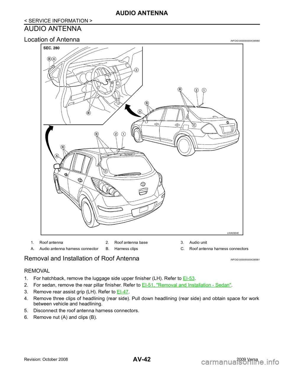
.
2. For sedan, remove the rear pillar finisher. Refer to EI-51, " Removal and Installation - Sedan " .
3. Remove rear assist grip (LH). Refer to EI-47 .
4. Remove three clips of headlining (rear side). Pull down headlining (rear side) and obtain space for work between vehicle and headlining.
5. Disconnect the roof antenna harness connectors.
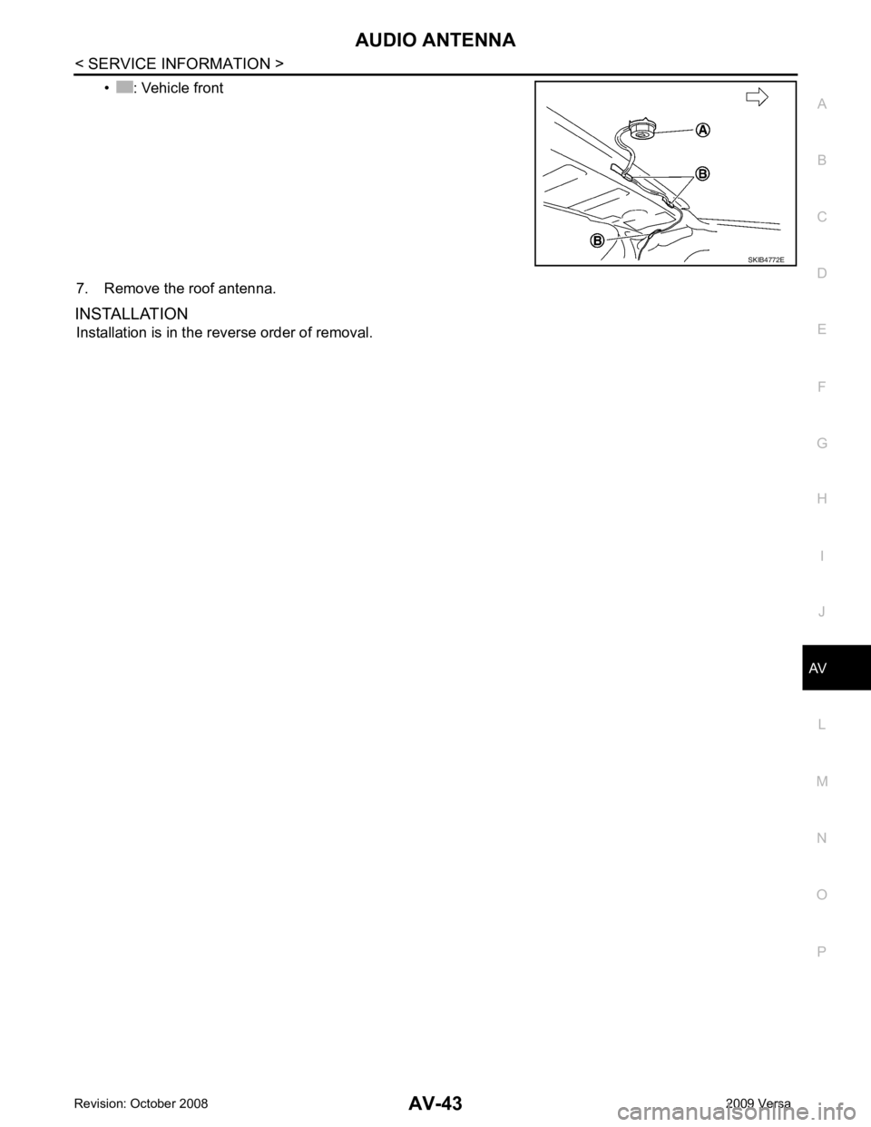
6. Remove nut (A) and clips (B).
Page 427 of 4331
AV
N
O P
• : Vehicle front
7. Remove the roof antenna.
INSTALLATION Installation is in the reverse order of removal.
Page 429 of 4331
AV
N
O P
tooth cellular telephones may not be recognized by t
he Bluetooth control unit. When a cellular telephone or
the Bluetooth control unit is replaced, the telephone must be paired with the Bluetooth control unit. Different
cellular telephones may have different pairing procedures. Refer to the cellular telephone operating manual.
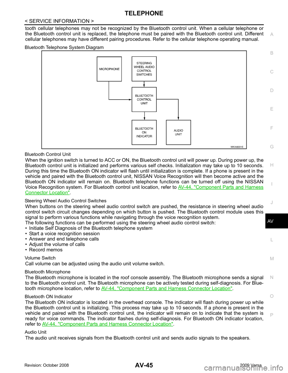
Bluetooth Telephone System Diagram
Bluetooth Control Unit When the ignition switch is turned to ACC or ON, the Bluetooth control unit will power up. During power up, the
Bluetooth control unit is initialized and performs various self checks. Initialization may take up to 10 seconds.
During this time the Bluetooth ON indicator will flash until initialization is complete. If a phone is present in the
vehicle and paired with the Bluetooth control unit, NIS SAN Voice Recognition will then become active and the
Bluetooth ON indicator will remain on. Bluetooth te lephone functions can be turned off using the NISSAN
Voice Recognition system. For Bluetooth control unit location, refer to AV-44, " Component Parts and Harness
Connector Location " .
Steering Wheel Audio Control Switches When buttons on the steering wheel audio control switch are pushed, the resistance in steering wheel audio
control switch circuit changes depending on which button is pushed. The Bluetooth control module uses this
signal to perform various functions while navigating through the voice recognition system.
The following functions can be performed usi ng the steering wheel audio control switch:
• Initiate Self Diagnosis of the Bluetooth telephone system
• Start a voice recognition session
• Answer and end telephone calls
• Adjust the volume of calls
• Record memos
Volume Switch Call volume can be adjusted using the audio unit volume switch.
Bluetooth Microphone The Bluetooth microphone is located in the roof c onsole assembly. The Bluetooth microphone sends a signal
to the Bluetooth control unit. The Bluetooth microphone can be actively tested during self-diagnosis. For Blue-
tooth microphone location, refer to AV-44, " Component Parts and Harness Connector Location " .
Bluetooth ON Indicator The Bluetooth ON indicator is located in the overhead console. The indicator will flash during power up while
the Bluetooth control unit is initializing. This process may take up to 10 seconds. If a phone is present in the
vehicle and paired with the Bluetooth control unit, the indi cator will remain on to indicate that the system is
ready for voice commands. The indicator flashes duri ng self-diagnosis. For Bluetooth ON indicator location,
refer to AV-44, " Component Parts and Harness Connector Location " .
Audio Unit The audio unit receives signals from the Bluetooth control unit and sends audio signals to the speakers.
Page 442 of 4331
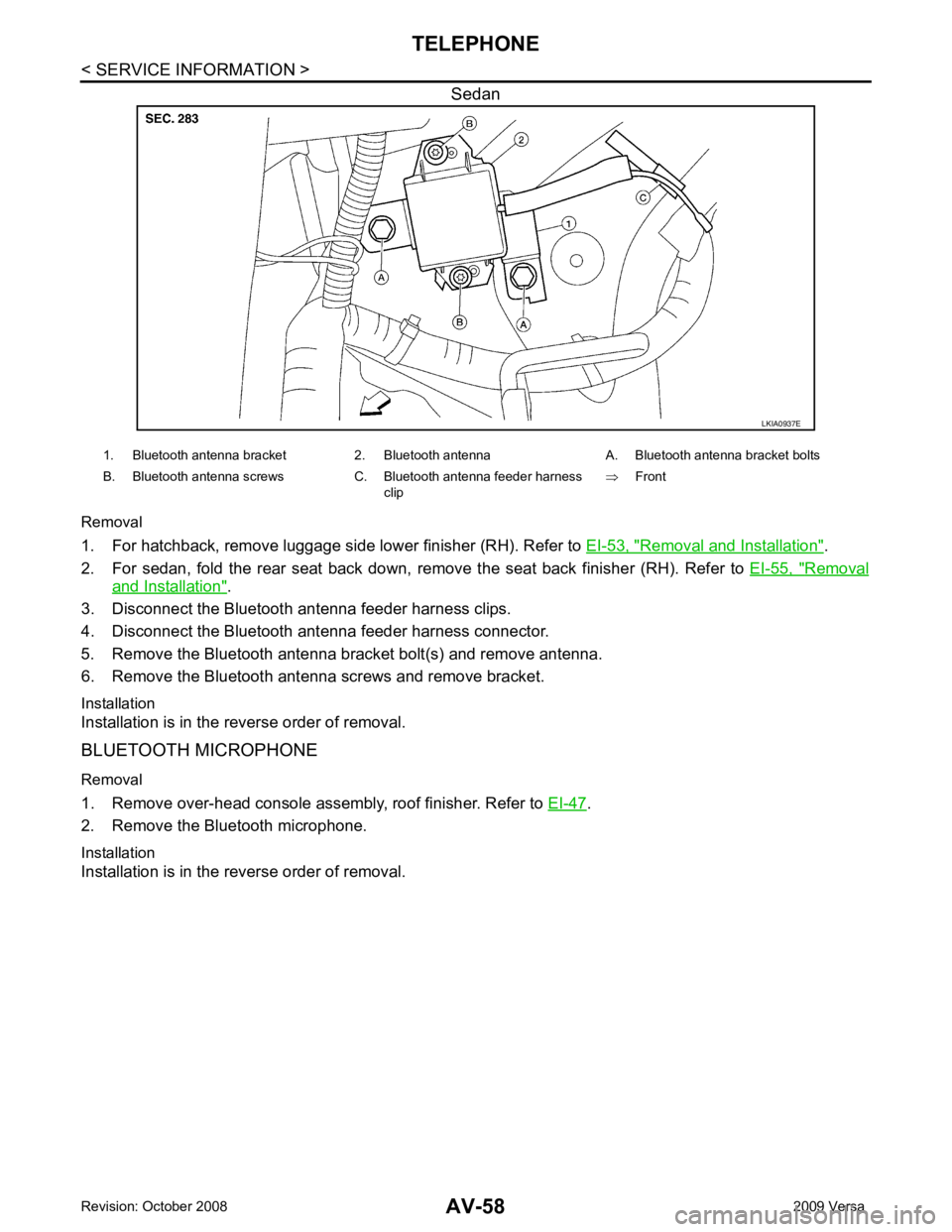
Removal and Installation " .
2. For sedan, fold the rear seat back down, re move the seat back finisher (RH). Refer to EI-55, " Removal
and Installation " .
3. Disconnect the Bluetooth antenna feeder harness clips.
4. Disconnect the Bluetooth ant enna feeder harness connector.
5. Remove the Bluetooth antenna bracket bolt(s) and remove antenna.
6. Remove the Bluetooth antenna screws and remove bracket.
Installation
Installation is in the reverse order of removal.
BLUETOOTH MICROPHONE
Removal
1. Remove over-head console assembly, roof finisher. Refer to EI-47 .
2. Remove the Bluetooth microphone.
Installation
Installation is in the reverse order of removal.
Page 448 of 4331

System Description " .
• Remote keyless entry system. Refer to BL-58, " System Description " .
• Power window system (with power windows). Refer to GW-19, " System Description " .
NOTE
• Sunroof system (with sunroof). Refer to RF-11, " System Description " .
NOTE
• Room lamp timer. Refer to LT-91, " System Description " .
• Rear wiper and washer system (Hatchback). Refer to WW-25, " System Description " .
NOTE:
Power supply only. No system control.
SYSTEMS CONTROLLED BY BCM AND IPDM E/R
• Panic system. Refer to BL-58, " System Description " .
• Vehicle security (theft warning) system. Refer to BL-219, " System Description " .
• NVIS(NATS) system. Refer to BL-248, " System Description " .
• Headlamp, tail lamp and battery saver control systems. Refer to LT-73, " System Description " ,
LT-4, " System
Description " or
LT-25, " System Description " .
• Front fog lamp (with front fog lamps). Refer to LT-39, " System Description " .
• Front wiper and washer system. Refer to WW-3, " System Description " .
• Rear window defogger system. Refer to GW-51, " System Description " .
SYSTEMS CONTROLLED BY BCM AND COMBINATION METER
• Warning chime. Refer to DI-42, " System Description " .
• Turn signal and hazard warning lamps. Refer to LT-48, " System Description " .
SYSTEMS CONTROLLED BY BCM AND INTELLIGENT KEY UNIT (WITH INTELLIGENT KEY)
• Intelligent Key system. Refer to BL-88, " System Description " .
MAJOR COMPONENTS AND CONTROL SYSTEM
System Input Output
Remote keyless entry system (with
power door locks) Remote keyless entry receiver
(keyfob) • All door locking actuators
• Turn signal lamp (LH, RH)
• Combination meter (turn signal lamp)
Intelligent Key system (with Intelligent
Key) Intelligent Key unit• All door locking actuators
• Turn signal lamp (LH, RH)
• Combination meter (turn signal lamp)
Power door lock system (with power
door locks) Front power door lock/unlock
switch (LH, RH) All door locking actuators
Power supply (IGN/RAP) to power
window (with power windows) Ignition retained power supply Power supply to power window and sunroof system
Power supply (BAT) to power window
(with power windows) Battery power supply Power supply to power window and sunroof system
Page 732 of 4331
BL
N
O P
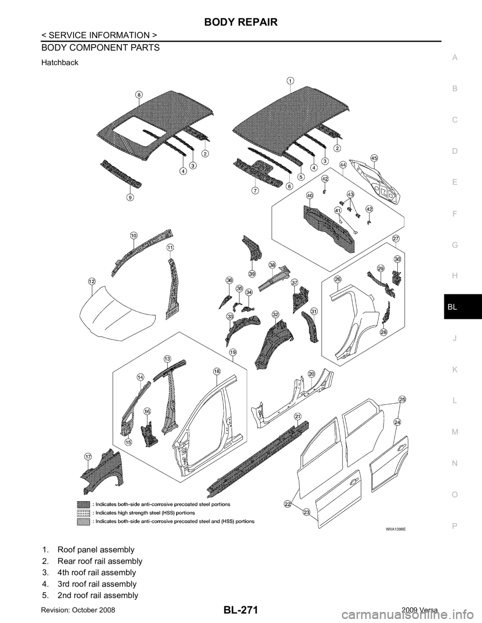
BODY COMPONENT PARTS
Hatchback
1. Roof panel assembly
2. Rear roof rail assembly
3. 4th roof rail assembly
4. 3rd roof rail assembly
5. 2nd roof rail assembly
Page 734 of 4331
BL
N
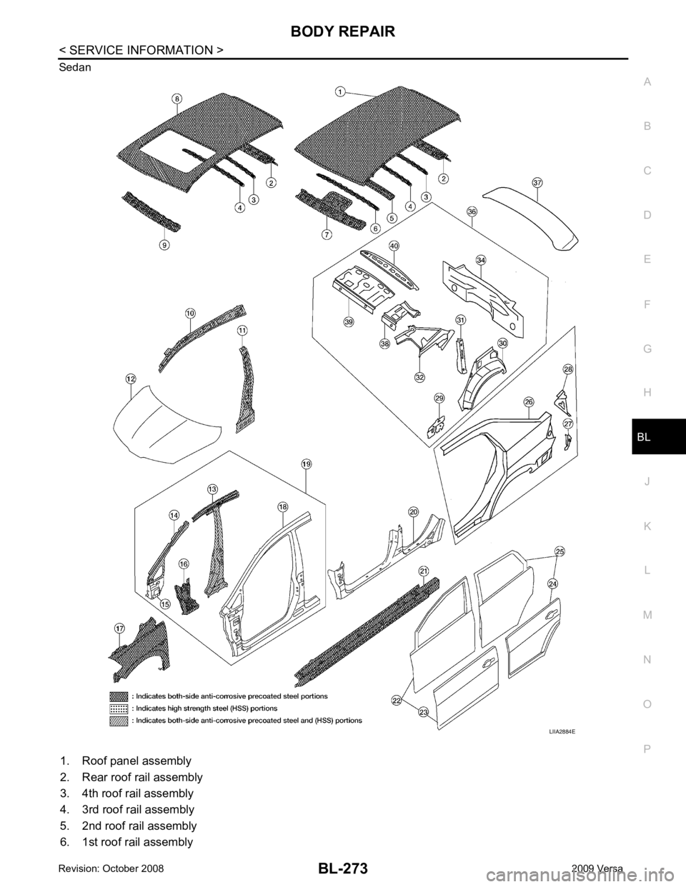
O P
Sedan
1. Roof panel assembly
2. Rear roof rail assembly
3. 4th roof rail assembly
4. 3rd roof rail assembly
5. 2nd roof rail assembly
6. 1st roof rail assembly