2009 NISSAN LATIO roof
[x] Cancel search: roofPage 2943 of 4331
EI-52< ON-VEHICLE REPAIR >
HEADLINING
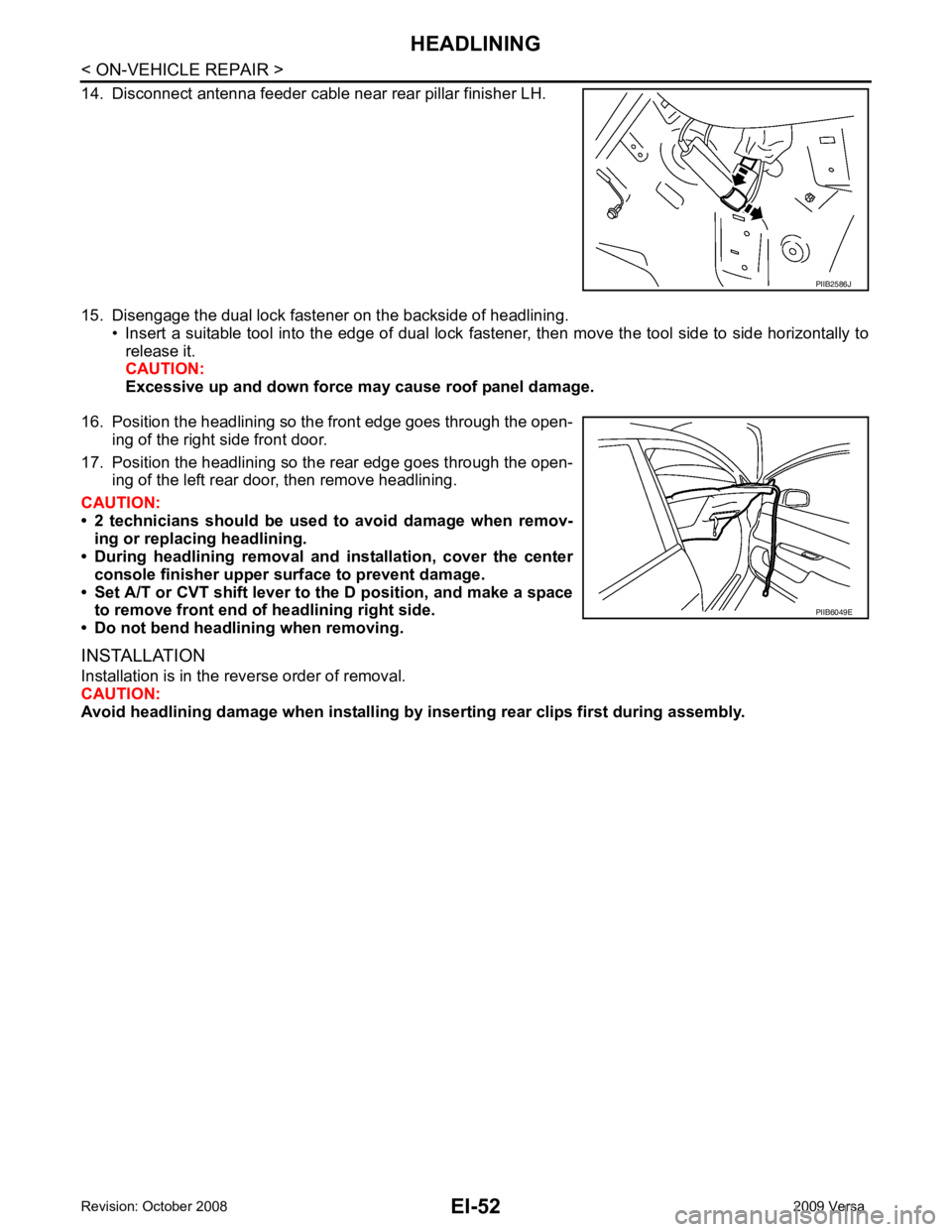
14. Disconnect antenna feeder cable near rear pillar finisher LH.
15. Disengage the dual lock fastener on the backside of headlining. • Insert a suitable tool into the edge of dual lock fastener, then move the tool side to side horizontally to
release it.
CAUTION:
Excessive up and down force may cause roof panel damage.
16. Position the headlining so the front edge goes through the open- ing of the right side front door.
17. Position the headlining so the rear edge goes through the open- ing of the left rear door, then remove headlining.
CAUTION:
• 2 technicians should be used to avoid damage when remov-
ing or replacing headlining.
• During headlining removal and installation, cover the center
console finisher upper surface to prevent damage.
• Set A/T or CVT shift lever to the D position, and make a space to remove front end of headlining right side.
• Do not bend headlining when removing.
INSTALLATION
Installation is in the reverse order of removal.
CAUTION:
Avoid headlining damage when installing by inserting rear clips first during assembly. PIIB2586J
PIIB6049E
Page 3312 of 4331

GW
N
O P
Most of these incidents can be repaired by adjusting, se
curing or insulating the item(s) or component(s) caus-
ing the noise.
SUNROOF/HEADLINING Noises in the sunroof/headlining area can often be traced to one of the following:
1. Sunroof lid, rail, linkage or seals making a rattle or light knocking noise
2. Sun visor shaft shaking in the holder
3. Front or rear windshield touching headliner and squeaking
Again, pressing on the components to stop the noise while duplicating the conditions can isolate most of these
incidents. Repairs usually consist of insulating with felt cloth tape.
OVERHEAD CONSOLE (FRONT AND REAR) Overhead console noises are often caused by the cons ole panel clips not being engaged correctly. Most of
these incidents are repaired by pushing up on the c onsole at the clip locations until the clips engage.
In addition look for:
1. Loose harness or harness connectors.
2. Front console map/reading lamp lense loose.
3. Loose screws at console attachment points.
SEATS When isolating seat noise it's important to note the pos ition the seat is in and the load placed on the seat when
the noise is present. These conditions should be duplic ated when verifying and isolating the cause of the
noise.
Cause of seat noise include:
1. Headrest rods and holder
2. A squeak between the seat pad cushion and frame
3. The rear seatback lock and bracket
These noises can be isolated by moving or pressing on the suspected components while duplicating the con-
ditions under which the noise occurs. Most of thes e incidents can be repaired by repositioning the component
or applying urethane tape to the contact area.
UNDERHOOD Some interior noise may be caused by components under the hood or on the engine wall. The noise is then
transmitted into the passenger compartment.
Causes of transmitted underhood noise include:
1. Any component mounted to the engine wall
2. Components that pass through the engine wall
3. Engine wall mounts and connectors
4. Loose radiator mounting pins
5. Hood bumpers out of adjustment
6. Hood striker out of adjustment
These noises can be difficult to isolate since they cannot be reached from the interior of the vehicle. The best
method is to secure, move or insulate one component at a time and test drive the vehicle. Also, engine RPM
or load can be changed to isolate the noise. Repairs c an usually be made by moving, adjusting, securing, or
insulating the component causing the noise.
Page 3333 of 4331
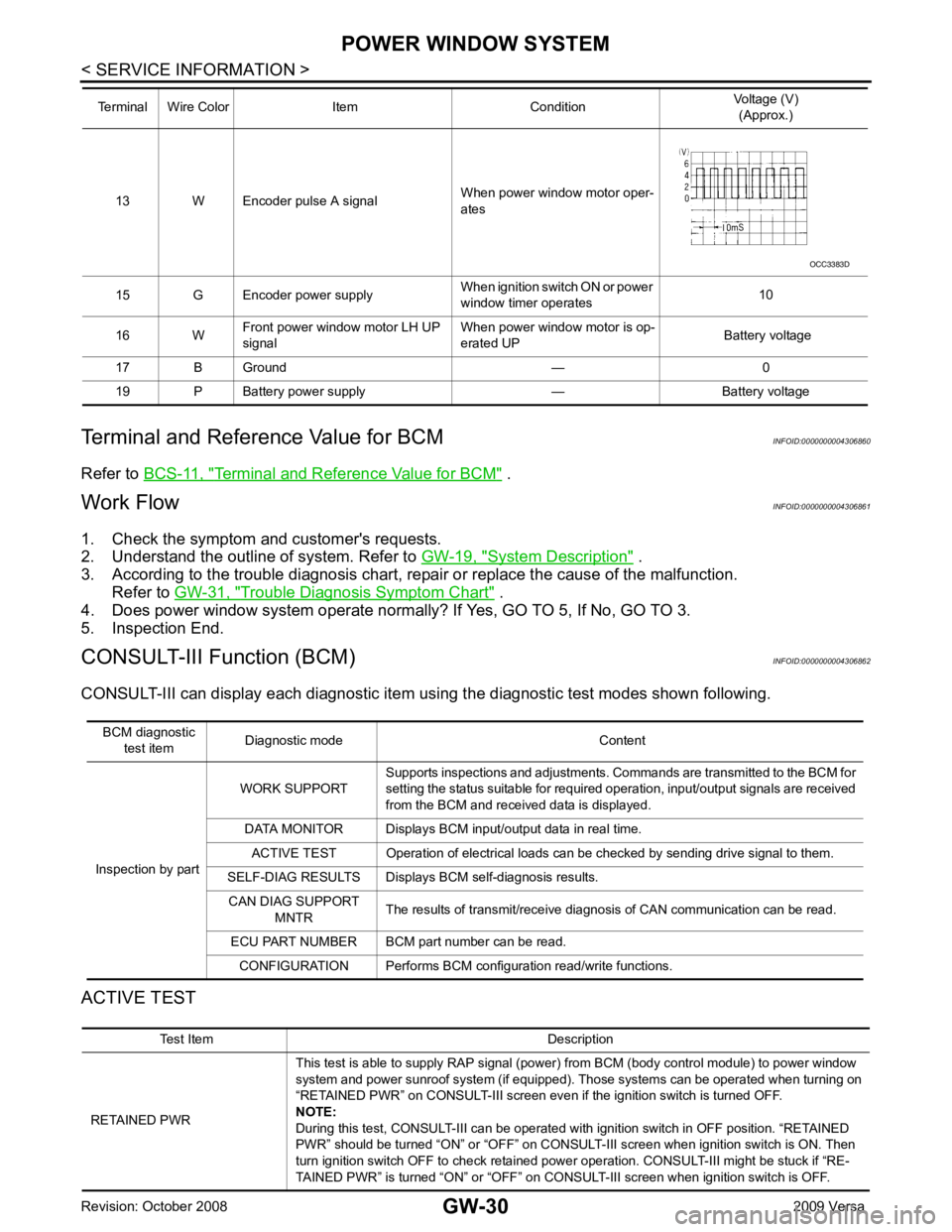
Terminal and Reference Value for BCM " .
Work Flow INFOID:0000000004306861
1. Check the symptom and customer's requests.
2. Understand the outline of system. Refer to GW-19, " System Description " .
3. According to the trouble diagnosis chart, repa ir or replace the cause of the malfunction.
Refer to GW-31, " Trouble Diagnosis Symptom Chart " .
4. Does power window system operate normally? If Yes, GO TO 5, If No, GO TO 3.
5. Inspection End.
CONSULT-III Function (BCM) INFOID:0000000004306862
CONSULT-III can display each diagnostic item us ing the diagnostic test modes shown following.
ACTIVE TEST 13 W Encoder pulse A signal
When power window motor oper-
ates
15 G Encoder power supply When ignition switch ON or power
window timer operates 10
16 W Front power window motor LH UP
signal When power window motor is op-
erated UP Battery voltage
17 B Ground — 0
19 P Battery power supply — Battery voltage
Terminal Wire Color Item Condition
Voltage (V)
(Approx.) Test Item Description
RETAINED PWR This test is able to supply RAP signal (powe
r) from BCM (body control module) to power window
system and power sunroof system (if equipped). Those systems can be operated when turning on
“RETAINED PWR” on CONSULT-III screen even if the ignition switch is turned OFF.
NOTE:
During this test, CONSULT-III can be operated with ignition switch in OFF position. “RETAINED
PWR” should be turned “ON” or “OFF” on CONSULT-III screen when ignition switch is ON. Then
turn ignition switch OFF to check retained power operation. CONSULT-III might be stuck if “RE-
TAINED PWR” is turned “ON” or “OFF” on CO NSULT-III screen when ignition switch is OFF.
Page 3998 of 4331
PG
N
O P
Fuse
INFOID:0000000004306651
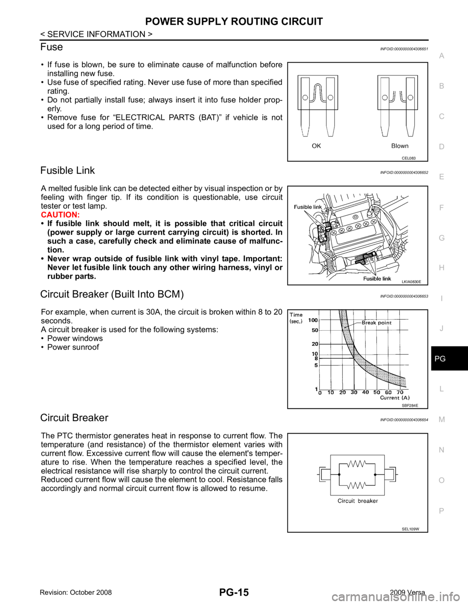
• If fuse is blown, be sure to eliminate cause of malfunction before installing new fuse.
• Use fuse of specified rating. Never use fuse of more than specified
rating.
• Do not partially install fuse; always insert it into fuse holder prop- erly.
• Remove fuse for “ELECTRICAL PARTS (BAT)” if vehicle is not
used for a long period of time.
Fusible Link INFOID:0000000004306652
A melted fusible link can be detected either by visual inspection or by
feeling with finger tip. If its condition is questionable, use circuit
tester or test lamp.
CAUTION:
• If fusible link should melt, it is possible that critical circuit
(power supply or large current carrying circuit) is shorted. In
such a case, carefully check and eliminate cause of malfunc-
tion.
• Never wrap outside of fusible li nk with vinyl tape. Important:
Never let fusible link touch any other wiring harness, vinyl or
rubber parts.
Circuit Breaker (B uilt Into BCM) INFOID:0000000004306653
For example, when current is 30A, the circuit is broken within 8 to 20
seconds.
A circuit breaker is used for the following systems:
• Power windows
• Power sunroof
Circuit Breaker INFOID:0000000004306654
The PTC thermistor generates heat in response to current flow. The
temperature (and resistance) of t he thermistor element varies with
current flow. Excessive current flow will cause the element's temper-
ature to rise. When the temperature reaches a specified level, the
electrical resistance will rise shar ply to control the circuit current.
Reduced current flow will cause the element to cool. Resistance falls
accordingly and normal circuit current flow is allowed to resume. LKIA0830E
SEL109W
Page 4082 of 4331

RF
N
O P
CONTENTS
ROOF
PRECAUTION ....... ........................................2
PRECAUTIONS .............................................. .....2
Precaution for Supplemental Restraint System
(SRS) "AIR BAG" and "SEAT BELT PRE-TEN-
SIONER" ............................................................. ......
2
Precaution Necessary fo r Steering Wheel Rota-
tion After Battery Disconnect ............................... ......
2
Precaution ........................................................... ......2
PREPARATION .... ........................................4
PREPARATION .............................................. .....4
Commercial Service Tool .................................... ......4
SYMPTOM DIAGNOSIS ..... ..........................5
SQUEAK AND RATTLE TROUBLE DIAG-
NOSES ........................ ........................................5
Work Flow ........................................................... ......5
Generic Squeak and Rattle Troubleshooting ...... ......7
Diagnostic Worksheet ......................................... ......9
FUNCTION DIAGNOSIS .. ............................11
TROUBLE DIAGNOSIS ................................. ....11 Component Parts and Harness Connector Loca-
tion ....................................................................... ....
11
System Description .............................................. ....11
CAN Communication System Description ........... ....13
Wiring Diagram - SROOF - .................................. ....14
Terminal and Reference Value for BCM ..................15
Terminal and Reference Value for Sunroof Motor
Assembly ............................................................. ....
16
Work Flow ............................................................ ....16
CONSULT-III Function (B CM) .................................16
Work Support ....................................................... ....17
Active Test ........................................................... ....17
Data Monitor ........................................................ ....17
Trouble Diagnosis Chart by Symptom ................. ....17
BCM Power Supply and Ground Circuit Inspection ....17
Sunroof Switch System Inspection ...................... ....17
Sunroof Motor Assembly Power Supply and
Ground Circuit Inspection .................................... ....
19
Door Switch Check .............................................. ....20
ON-VEHICLE REPAIR ..... ............................22
SUNROOF ......................................................... 22
Removal and Installation ..................................... ....22
Fitting Adjustment ................................................ ....27
Inspection ............................................................ ....28
Page 4092 of 4331
RF
N
O P
FUNCTION DIAGNOSIS
TROUBLE DIAGNOSIS
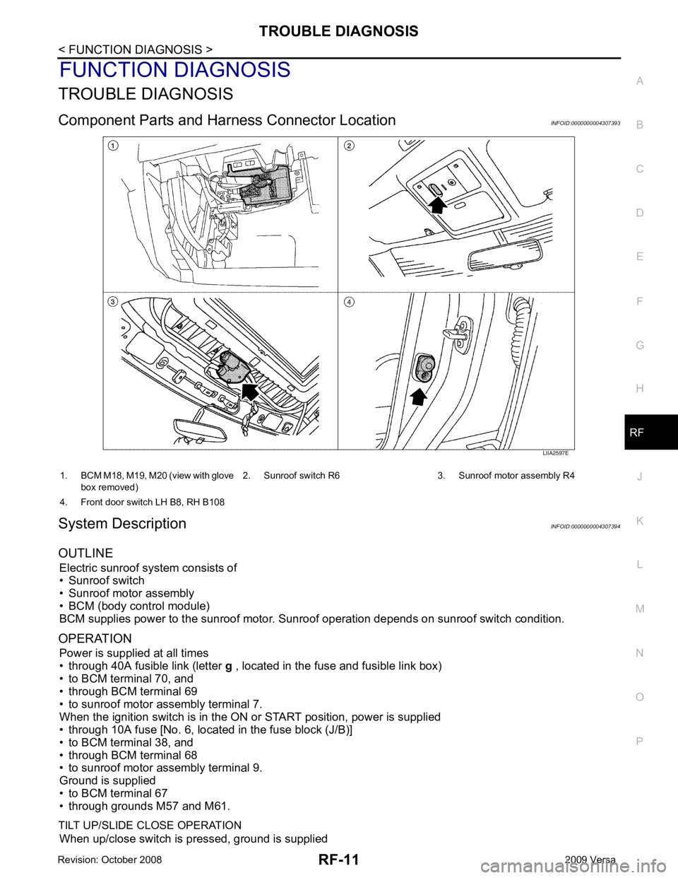
Component Parts and Har ness Connector Location INFOID:0000000004307393
System Description INFOID:0000000004307394
OUTLINE Electric sunroof system consists of
• Sunroof switch
• Sunroof motor assembly
• BCM (body control module)
BCM supplies power to the sunroof motor. S unroof operation depends on sunroof switch condition.
OPERATION Power is supplied at all times
• through 40A fusible link (letter g , located in the fuse and fusible link box)
• to BCM terminal 70, and
• through BCM terminal 69
• to sunroof motor assembly terminal 7.
When the ignition switch is in the ON or START position, power is supplied
• through 10A fuse [No. 6, located in the fuse block (J/B)]
• to BCM terminal 38, and
• through BCM terminal 68
• to sunroof motor assembly terminal 9.
Ground is supplied
• to BCM terminal 67
• through grounds M57 and M61.
TILT UP/SLIDE CLOSE OPERATION When up/close switch is pressed, ground is supplied
Page 4093 of 4331
Work Support " .
ANTI-PINCH FUNCTION
The CPU (central processing unit) of sunroof motor as sembly monitors the sunroof motor operation and the
sunroof position (fully-closed or other ) by the signals from sunroof motor.
When sunroof motor detects an interruption during the following slide close and tilt down operation, sunroof
switch controls the motor for open and the sunroof will oper ate until it reaches full up position (during tilt down
operation) or 125 mm (4.92 in) or more in an open direction (during slide close operation).
• close operation and tilt down when igniti on switch is in the ON position.
• close operation and tilt down during retained power operation.
INITIALIZATION FAILURE CONDITIONS
Initialization and teaching of system should be conducted if the following conditions exist:
• sunroof will only move in the UP/CLOSE direction, having a step by step motion
• sunroof does not have any auto operation.
INITIALIZATION PROCEDURE
If the sunroof does not close or open automatically, use the following procedure to return sunroof operation to
normal.
1. Press the switch to the UP/CLOSE position to tilt t he sunroof up fully. When the sunroof reaches the full tilt
up position it will back up a few millimeters and stop.
2. Release the UP/CLOSE switch.
3. Within 5 seconds of releasing the UP/CLOSE sw itch, press and hold the UP/CLOSE switch again. The
sunroof will move to the full open position and back to the closed position.
NOTE:
If the UP/CLOSE switch is released anytime during th is teaching process, all learned profile data will be dis-
carded and the procedure will have to be started over.
4. Release the UP/CLOSE switch. Do not disconnect power for at least two seconds. The sunroof is now ini-
tialized and taught.
Initializing procedure is complete. Confirm proper operation of the sunroof (slide open, slide closed, tilt up, tilt
down).
RE-TEACHING CONDITIONS
Re-teaching of system should be conducted if any of the following conditions exist:
• the sunroof is manually operated using the sunroof wrench with the battery discharged or disconnected.
• the sunroof is manually operated using the sunroof wrench with the key switch in the OFF position and
retained power timed out (after approximat ely 45 seconds or with a front door open).
• the sunroof motor assembly is replaced with a new one.
• the sunroof motor is removed from the sunroof assembly and operated before it is reinstalled.
Page 4094 of 4331
RF
N
O P
• the sunroof motor is removed from the sunroof
assembly and the glass panel position is changed.
RE-TEACHING PROCEDURE 1. Using the UP/CLOSE switch, move the sunroo f toward the tilt position until it stops.
2. Release the UP/CLOSE switch.
3. Press the UP/CLOSE switch again and continuously hold. The sunroof will begin to move in about 10 sec- onds.
4. Continue to hold the UP/CLOSE switch while the sunroof moves in a jogging motion to the full tilt position.
When the sunroof reaches the full tilt positi on, it will back up a few millimeters and stop.
5. Release the UP/CLOSE switch.
6. Within 5 seconds of releasing the UP/CLOSE s witch, press and hold the UP/CLOSE switch again. The
sunroof will move to the full open pos ition and back to the closed position.
NOTE:
If the UP/CLOSE switch is released anytime during th is teaching process, all learned profile data will be dis-
carded and the procedure will have to be started over.
7. Release the UP/CLOSE switch. Do not disconnect power for at least two seconds. The sunroof is now re-
taught.
CAN Communication System Description INFOID:0000000004307395
Refer to LAN-8 .