2009 NISSAN LATIO timing belt
[x] Cancel search: timing beltPage 841 of 4331
BRC
N
O P
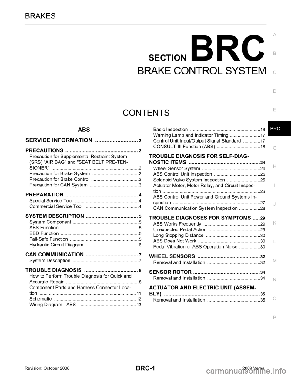
CONTENTS
BRAKE CONTROL SYSTEM
ABS
SERVICE INFORMATION .. ..........................
2
PRECAUTIONS .............................................. .....2
Precaution for Supplemental Restraint System
(SRS) "AIR BAG" and "SEAT BELT PRE-TEN-
SIONER" ............................................................. ......
2
Precaution for Brake System .............................. ......2
Precaution for Brake Cont rol .....................................3
Precaution for CAN System ................................ ......3
PREPARATION .............................................. .....4
Special Service Tool ........................................... ......4
Commercial Service Tool .................................... ......4
SYSTEM DESCRIPTION ................................ .....5
System Component ............................................. ......5
ABS Function ...................................................... ......5
EBD Function ...................................................... ......5
Fail-Safe Function ............................................... ......5
Hydraulic Circuit Diagram .........................................6
CAN COMMUNICATION ................................ .....7
System Description ............................................. ......7
TROUBLE DIAGNOSIS ................................. .....8
How to Perform Trouble Diagnosis for Quick and
Accurate Repair ........... .............................................
8
Component Parts and Harness Connector Loca-
tion ...................................................................... ....
11
Schematic ........................................................... ....12
Wiring Diagram - ABS - ... ........................................13 Basic Inspection ..................................................
....16
Warning Lamp and Indicator Timing .................... ....17
Control Unit Input/Output Signal Standard .......... ....17
CONSULT-III Function ( ABS) ..................................18
TROUBLE DIAGNOSIS FOR SELF-DIAG-
NOSTIC ITEMS ................................................. 24
Wheel Sensor System ......................................... ....24
ABS Control Unit Inspection ................................ ....25
Solenoid Valve System Inspection ...................... ....25
Actuator Motor, Motor Re lay, and Circuit Inspec-
tion ....................................................................... ....
26
ABS Control Unit Power and Ground Systems In-
spection ............................................................... ....
27
CAN Communication System Inspection ............. ....28
TROUBLE DIAGNOSES FOR SYMPTOMS ..... 29
ABS Works Frequently ........................................ ....29
Unexpected Pedal Action .................................... ....29
Long Stopping Distance ...................................... ....30
ABS Does Not Work ............................................ ....30
Pedal Vibration or ABS Op eration Noise .................30
WHEEL SENSORS ........................................... 32
Removal and Installation ..................................... ....32
SENSOR ROTOR .............................................. 34
Removal and Installation ..................................... ....34
ACTUATOR AND ELECTRIC UNIT (ASSEM-
BLY) .................................................................. 35
Removal and Installation ..................................... ....35
Page 1363 of 4331
EC
A
N
O P
Inspection ............................................................
..
500
ON-VEHICLE REPAIR .... ...........................502
EVAP CANISTER ........................................... ..502
Exploded View .................................................... ..502
Removal and Installation .......................................502
Inspection ............................................................ ..503
SERVICE DATA AND SPECIFICATIONS
(SDS) ......... ................................. ................504
SERVICE DATA AND SPECIFICATIONS
(SDS) .............................................................. ..504
Idle Speed ........................................................... ..504
Ignition Timing ..................................................... ..504
Calculated Load Value ........................................ ..504
Mass Air Flow Sensor ......................................... ..504
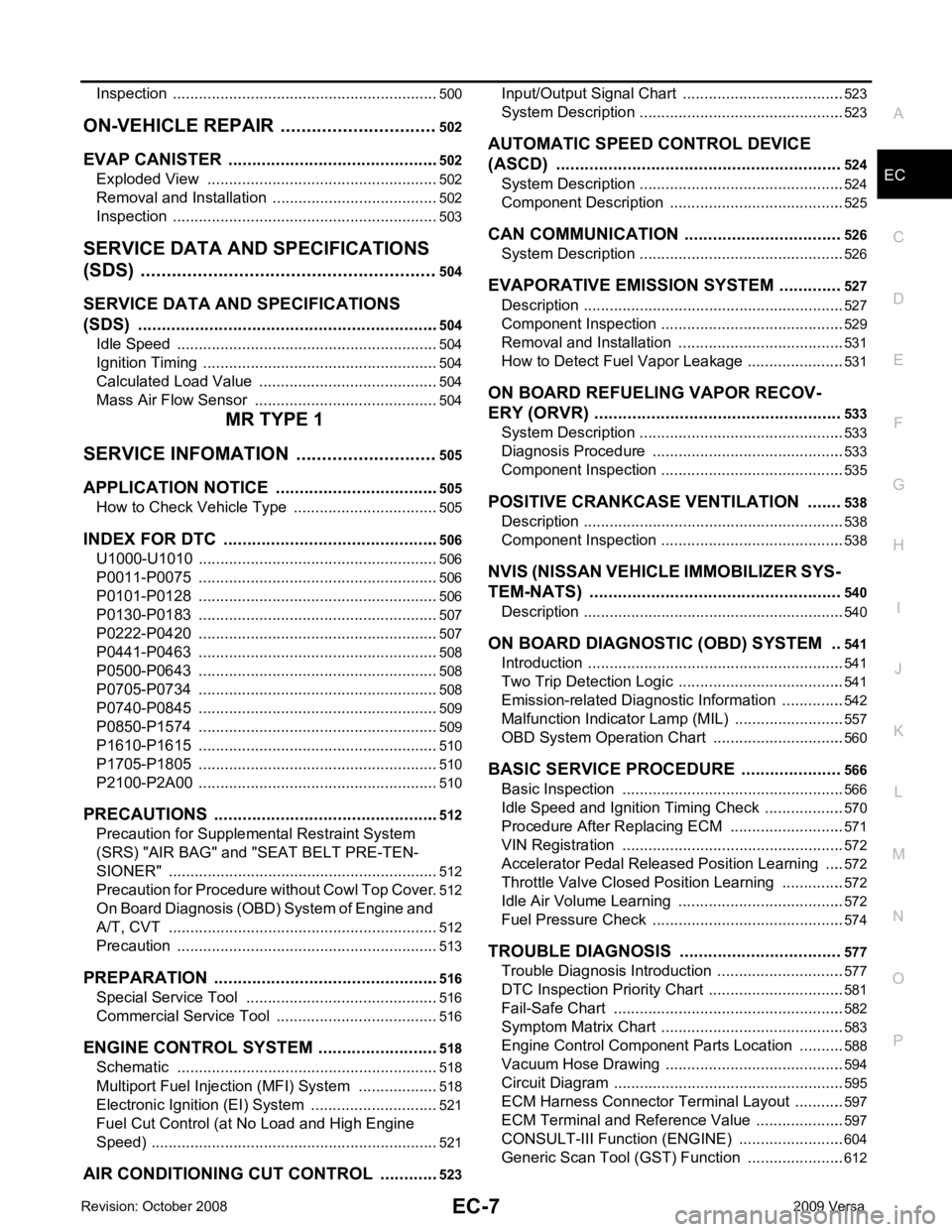
MR TYPE 1
SERVICE INFOMATION .. ..........................505
APPLICATION NOTICE ................................. ..505
How to Check Vehicle Type ................................ ..505
INDEX FOR DTC ............................................ ..506
U1000-U1010 ...................................................... ..506
P0011-P0075 ...................................................... ..506
P0101-P0128 ...................................................... ..506
P0130-P0183 ...................................................... ..507
P0222-P0420 ...................................................... ..507
P0441-P0463 ...................................................... ..508
P0500-P0643 ...................................................... ..508
P0705-P0734 ...................................................... ..508
P0740-P0845 ...................................................... ..509
P0850-P1574 ...................................................... ..509
P1610-P1615 ...................................................... ..510
P1705-P1805 ...................................................... ..510
P2100-P2A00 ...................................................... ..510
PRECAUTIONS .............................................. ..512
Precaution for Supplemental Restraint System
(SRS) "AIR BAG" and "SEAT BELT PRE-TEN-
SIONER" ............................................................. ..
512
Precaution for Procedure without Cowl Top Cover ..512
On Board Diagnosis (OBD) System of Engine and
A/T, CVT ............................................................. ..
512
Precaution ........................................................... ..513
PREPARATION .............................................. ..516
Special Service Tool ........................................... ..516
Commercial Service Tool .................................... ..516
ENGINE CONTROL SYSTEM ........................ ..518
Schematic ........................................................... ..518
Multiport Fuel Injection (MFI) System ................. ..518
Electronic Ignition (EI) System ............................ ..521
Fuel Cut Control (at No Load and High Engine
Speed) ................................................................. ..
521
AIR CONDITIONING CUT CONTROL ........... ..523 Input/Output Signal Chart ....................................
..523
System Description .............................................. ..523
AUTOMATIC SPEED CONTROL DEVICE
(ASCD) ............................................................ 524
System Description .............................................. ..524
Component Description ....................................... ..525
CAN COMMUNICATION ................................. 526
System Description .............................................. ..526
EVAPORATIVE EMISSION SYSTEM ............. 527
Description ........................................................... ..527
Component Inspection ......................................... ..529
Removal and Installation ..................................... ..531
How to Detect Fuel Vapor Leakage ..................... ..531
ON BOARD REFUELING VAPOR RECOV-
ERY (ORVR) .................................................... 533
System Description .............................................. ..533
Diagnosis Procedure ........................................... ..533
Component Inspection ......................................... ..535
POSITIVE CRANKCASE VENTILATION ....... 538
Description ........................................................... ..538
Component Inspection ......................................... ..538
NVIS (NISSAN VEHICLE IMMOBILIZER SYS-
TEM-NATS) ..................................................... 540
Description ........................................................... ..540
ON BOARD DIAGNOSTIC (OBD) SYSTEM .. 541
Introduction .......................................................... ..541
Two Trip Detection Logic ..................................... ..541
Emission-related Diagnostic Information ............. ..542
Malfunction Indicator Lamp (MIL) ..........................557
OBD System Operation Chart ............................. ..560
BASIC SERVICE PROCEDURE ..................... 566
Basic Inspection .................................................. ..566
Idle Speed and Ignition Timing Check ................. ..570
Procedure After Replacing ECM ......................... ..571
VIN Registration .................................................. ..572
Accelerator Pedal Released Position Learning ... ..572
Throttle Valve Closed Position Learning ............. ..572
Idle Air Volume Learning ..................................... ..572
Fuel Pressure Check ........................................... ..574
TROUBLE DIAGNOSIS .................................. 577
Trouble Diagnosis Introduction ............................ ..577
DTC Inspection Priority Chart .............................. ..581
Fail-Safe Chart .................................................... ..582
Symptom Matrix Chart ......................................... ..583
Engine Control Component Parts Location ......... ..588
Vacuum Hose Drawing ........................................ ..594
Circuit Diagram .................................................... ..595
ECM Harness Connector Terminal Layout .......... ..597
ECM Terminal and Reference Value ................... ..597
CONSULT-III Function (ENGINE) ....................... ..604
Generic Scan Tool (GST) Function ..................... ..612
Page 2960 of 4331
EM
NP
O
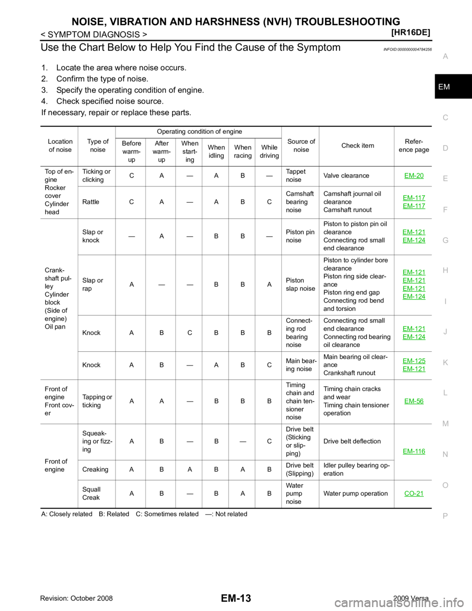
Use the Chart Below to Help You
Find the Cause of the Symptom INFOID:0000000004784256
1. Locate the area where noise occurs.
2. Confirm the type of noise.
3. Specify the operating condition of engine.
4. Check specified noise source.
If necessary, repair or replace these parts.
A: Closely related B: Related C: Sometimes related —: Not related Location
of noise Type of
noise Operating condition of engine
Source of noise Check item Refer-
ence page
Before
warm- up After
warm- up When
start- ing When
idling When
racing While
driving
Top of en-
gine
Rocker
cover
Cylinder
head Ticking or
clicking C A — A B — Tappet
noise Valve clearance
EM-20 Rattle C A — A B C
Camshaft
bearing
noise Camshaft journal oil
clearance
Camshaft runout EM-117 EM-117
Crank-
shaft pul-
ley
Cylinder
block
(Side of
engine)
Oil pan Slap or
knock — A — B B —
Piston pin
noise Piston to piston pin oil
clearance
Connecting rod small
end clearance EM-121 EM-124
Slap or
rap A — — B B A
Piston
slap noise Piston to cylinder bore
clearance
Piston ring side clear-
ance
Piston ring end gap
Connecting rod bend
and torsion EM-121 EM-121
EM-121
EM-124
Knock A B C B B B
Connect-
ing rod
bearing
noise Connecting rod small
end clearance
Connecting rod bearing
oil clearance EM-121 EM-124
Knock A B — A B C
Main bear-
ing noise Main bearing oil clear-
ance
Crankshaft runout EM-125 EM-121
Front of
engine
Front cov-
er Tapping or
ticking A A — B B B Timing
chain and
chain ten-
sioner
noise Timing chain cracks
and wear
Timing chain tensioner
operation EM-56Front of
engine Squeak-
ing or fizz-
ing A B — B — C Drive belt
(Sticking
or slip-
ping) Drive belt deflection
EM-116 Creaking A B A B A B
Drive belt
(Slipping) Idler pulley bearing op-
eration
Squall
Creak A B — B A B Water
pump
noise Water pump operation
CO-21
Page 2997 of 4331
![NISSAN LATIO 2009 Service Repair Manual EM-50< ON-VEHICLE REPAIR >
[HR16DE]
TIMING CHAIN
4. Remove the following parts. • Intake manifold: Refer to EM-28, " Exploded View " .
• Drive belt: Refer to EM-15, " Removal and Installation " NISSAN LATIO 2009 Service Repair Manual EM-50< ON-VEHICLE REPAIR >
[HR16DE]
TIMING CHAIN
4. Remove the following parts. • Intake manifold: Refer to EM-28, " Exploded View " .
• Drive belt: Refer to EM-15, " Removal and Installation "](/manual-img/5/57359/w960_57359-2996.png)
EM-50< ON-VEHICLE REPAIR >
[HR16DE]
TIMING CHAIN
4. Remove the following parts. • Intake manifold: Refer to EM-28, " Exploded View " .
• Drive belt: Refer to EM-15, " Removal and Installation " .
• Water pump pulley: Refer to CO-20, " Exploded View " .
• Ground cable (RH)
5. Support the bottom surface of engine using a tr ansmission jack, and then remove the engine mounting
bracket and insulator (RH). Refer to EM-88, " Exploded View " .
6. Remove rocker cover. Refer to EM-46, " Exploded View " .
7. Set No. 1 cylinder at TDC of its compression stroke with the following procedure:
a. Rotate crankshaft pulley (2) clockwise and align TDC mark (without paint mark) (A) to timing indicator (1) on front cover.
b. Make sure the matching marks on each camshaft sprocket are positioned as shown.
• If not, rotate crankshaft pulley one more turn to align matching marks to the positions.
8. Remove crankshaft pulley with the following procedure:
a. Secure crankshaft pulley (1) using a suitable tool (A).
b. Loosen and pull out crankshaft pulley bolts. CAUTION:
Never remove the bolts as they are used as a supporting
point for the pulley puller.
c. Attach Tool (A) in the M 6 thread hole on crankshaft pulley, and remove crankshaft pulley. B : White paint mark (Not use for service) PBIC3673E
1 : Camshaft sprocket (EXH)
2 : Camshaft sprocket (INT)
A : Matching mark (stamp)
B : Matching mark (peripheral stamp line) PBIC3872E
PBIC3710E
B : M6 bolt
Tool number : KV11103000 ( — ) PBIC3711E
Page 3005 of 4331
Rotation " .
2. Remove front fender protector (RH). Refer to EI-24, " Removal and Installation " .
3. Drain engine oil. Refer to LU-8, " Draining " .
CAUTION:
Be sure to perform this step when engine is cold.
4. Remove the following parts. • Intake manifold: Refer to EM-28, " Exploded View " .
• Drive belt: Refer to EM-15, " Removal and Installation " .
• Water pump pulley: Refer to CO-20, " Exploded View " .
• Ground cable (RH)
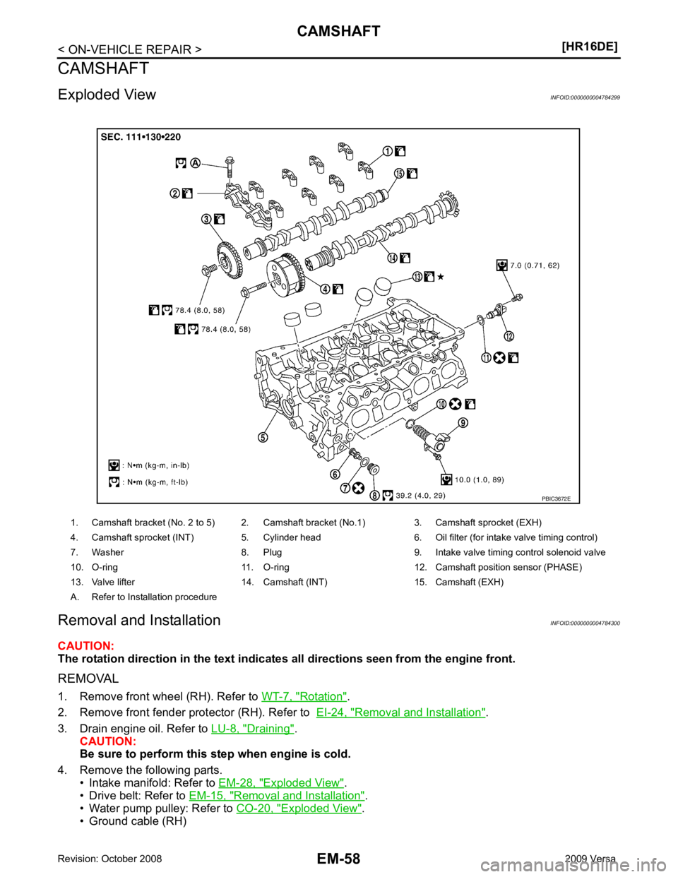
1. Camshaft bracket (No. 2 to 5) 2. Camshaft bracket (No.1) 3. Camshaft sprocket (EXH)
4. Camshaft sprocket (INT) 5. Cylinder head 6. Oil filter (for intake valve timing control)
7. Washer 8. Plug 9. Intake valve timing control solenoid valve
10. O-ring 11. O-ring 12. Camshaf t position sensor (PHASE)
13. Valve lifter 14. Camshaft (INT) 15. Camshaft (EXH)
A. Refer to Installation procedure
Page 3021 of 4331
Fluids and Lubricants " .
• Use procedure below to check for fuel leakage.
- Turn ignition switch “ON” (with engine stopped). With fuel pressure applied to fuel piping, check for fuel leak-
age at connection points.
- Start engine. With engine speed increased, che ck again for fuel leakage at connection points.
• Run engine to check for unusual noise and vibration. NOTE:
If hydraulic pressure inside timing chain tensioner drops after removal/installation, slack in the guide may
generate a pounding noise during and just after engine start. However, this is normal. Noise will stop after
hydraulic pressure rises.
• Warm up engine thoroughly to make sure there is no leakage of fuel, or any oil/fluids including engine oil and
engine coolant.
• Bleed air from lines and hoses of applicable lines, such as in cooling system.
• After cooling down engine, again check oil/fluid levels including engine oil and engine coolant. Refill to the
specified level, if necessary.
Summary of the inspection items:
*: Transmission/transaxle/CVT fluid, power steering fluid, brake fluid, etc.
Inspection of Camshaft Sprocket (INT) Oil Groove
CAUTION:
• Perform this inspection only when DTC P0011 is de tected in self-diagnostic results of CONSULT-III
and it is directed according to inspect ion procedure of EC section. Refer to EC-133, " Diagnosis Pro-
cedure " .
• Check when engine is cold so as to pr event burns from the splashing engine oil.
1. Check engine oil level. Refer to LU-7, " Inspection " .
2. Perform the following procedure so as to prevent the engine from being unintentionally started while
checking.
a. Release the fuel pressure. Refer to EC-498, " Inspection " .
b. Remove intake manifold. Refer to EM-28, " Exploded View " .
c. Disconnect ignition coil and injector harness connectors. Refer to EM-46, " Exploded View " .
3. Remove intake valve timing control solenoid valve. Refer to EM-49, " Exploded View " .
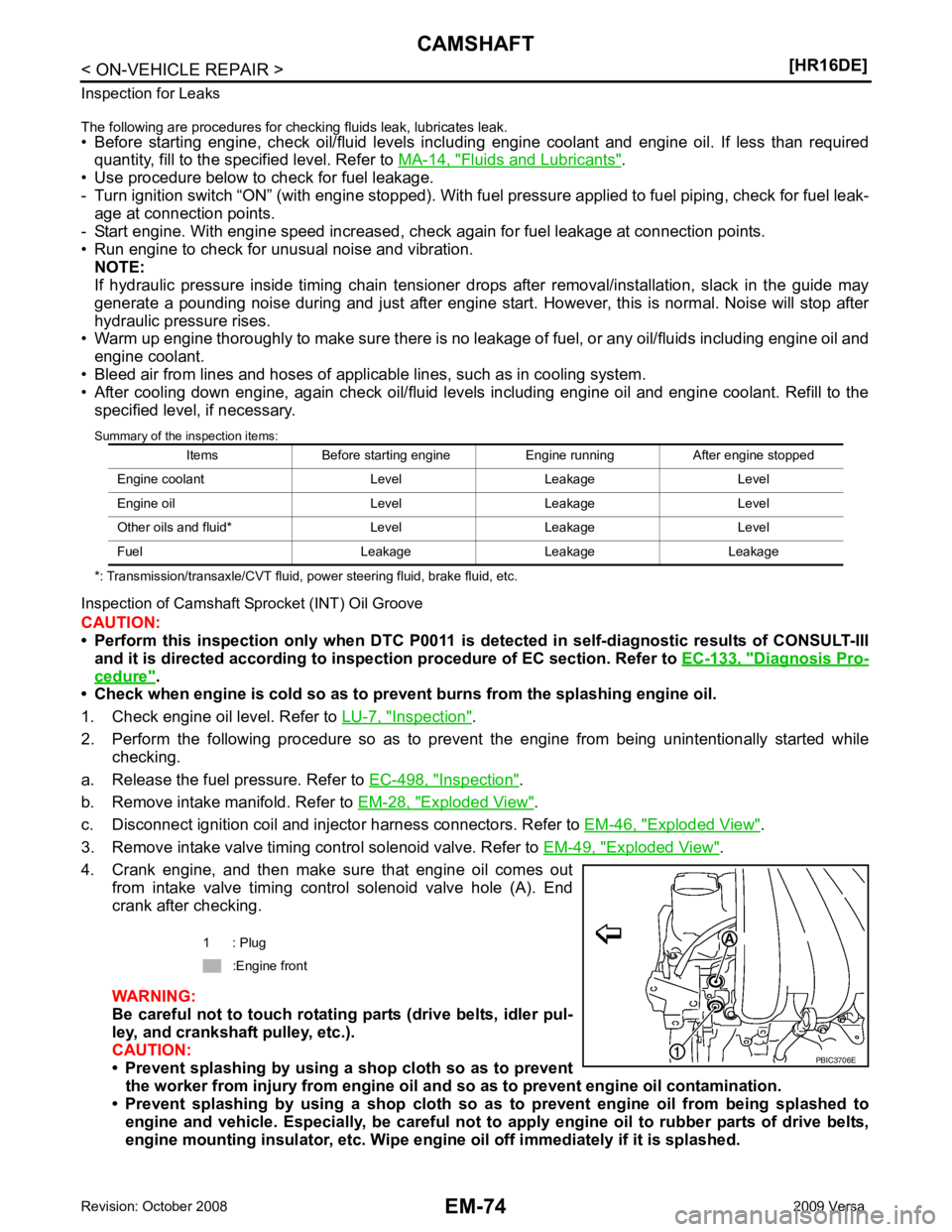
4. Crank engine, and then make sure that engine oil comes out from intake valve timing control solenoid valve hole (A). End
crank after checking.
WARNING:
Be careful not to touch rotating parts (drive belts, idler pul-
ley, and crankshaft pulley, etc.).
CAUTION:
• Prevent splashing by using a shop cloth so as to prevent
the worker from injury from engine oil an d so as to prevent engine oil contamination.
• Prevent splashing by using a shop cloth so as to prevent engine oil from being splashed to
engine and vehicle. Especially, be careful not to apply engine oil to rubber parts of drive belts,
engine mounting insulator, etc. Wipe engi ne oil off immediately if it is splashed.
Items Before starting engine Engine running After engine stopped
Engine coolant Level Leakage Level
Engine oil Level Leakage Level
Other oils and fluid* Level Leakage Level
Fuel Leakage Leakage Leakage 1 : Plug
:Engine front
Page 3024 of 4331
EM
NP
O
FRONT OIL SEAL : Remo
val and Installation INFOID:0000000004784303
REMOVAL 1. Remove the following parts: • Front fender protector (RH): Refer to EI-24, " Removal and Installation " .
• Drive belt: Refer to EM-15, " Removal and Installation " .
• Crankshaft pulley: Refer to EM-49, " Exploded View " .
2. Remove front oil seal using a suitable tool. CAUTION:
Be careful not to damage fron t timing chain case and crankshaft.
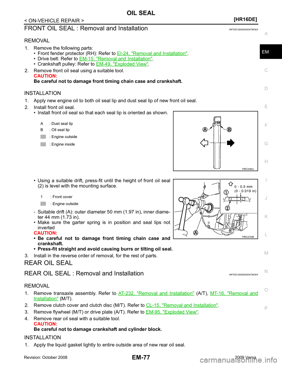
INSTALLATION 1. Apply new engine oil to both oil seal lip and dust seal lip of new front oil seal.
2. Install front oil seal. • Install front oil seal so that each seal lip is oriented as shown.
• Using a suitable drift, press-fit until the height of front oil seal (2) is level with the mounting surface.
- Suitable drift (A): outer diameter 50 mm (1.97 in), inner diame- ter 44 mm (1.73 in).
• Make sure the garter spring is in position and seal lips not
inverted
CAUTION:
• Be careful not to damage front timing chain case and
crankshaft.
• Press-fit straight and avoid cau sing burrs or tilting oil seal.
3. Install in the reverse order of removal, for the rest of parts.
REAR OIL SEAL
REAR OIL SEAL : Removal and Installation INFOID:0000000004784304
REMOVAL 1. Remove transaxle assembly. Refer to AT-232, " Removal and Installation " (A/T),
MT-16, " Removal and
Installation " (M/T).
2. Remove clutch cover and clutch disc (M/T). Refer to CL-15, " Removal and Installation " .
3. Remove flywheel (M/T) or drive plate (A/T). Refer to EM-95, " Exploded View " .
4. Remove rear oil seal with a suitable tool. CAUTION:
Be careful not to damage crankshaft and cylinder block.
INSTALLATION 1. Apply the liquid gasket lightly to entire outside area of new rear oil seal. A : Dust seal lip
B : Oil seal lip
: Engine outside
: Engine inside
Page 3082 of 4331
EM
NP
O
Use the Chart Below to Help You
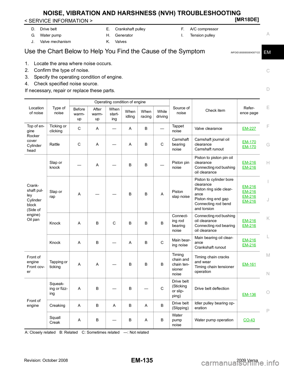
Find the Cause of the Symptom INFOID:0000000004307122
1. Locate the area where noise occurs.
2. Confirm the type of noise.
3. Specify the operating condition of engine.
4. Check specified noise source.
If necessary, repair or replace these parts.
A: Closely related B: Related C: Sometimes related —: Not related D. Drive belt E. Crankshaft pulley F. A/C compressor
G. Water pump H. Generator I. Tension pulley
J. Valve mechanism K. Valves
Location of noise Type of
noise Operating condition of engine
Source of noise Check item
Refer-
ence page
Before
warm-
up After
warm-
up When
start-
ing When
idling When
racing While
driving
Top of en-
gine
Rocker
cover
Cylinder
head Ticking or
clicking C A — A B —
Tappet
noise Valve clearance
EM-227 Rattle C A — A B C
Camshaft
bearing
noise Camshaft journal oil
clearance
Camshaft runout EM-170 EM-170
Crank-
shaft pul-
ley
Cylinder
block
(Side of
engine)
Oil pan Slap or
knock — A — B B —
Piston pin
noise Piston to piston pin oil
clearance
Connecting rod bushing
oil clearance EM-216 EM-216
Slap or
rap A — — B B A
Piston
slap noise Piston to cylinder bore
clearance
Piston ring side clear-
ance
Piston ring end gap
Connecting rod bend
and torsion EM-216 EM-216
EM-216
EM-216
Knock A B C B B B
Connect-
ing rod
bearing
noise Connecting rod bushing
oil clearance
Connecting rod bearing
oil clearance EM-216 EM-216
Knock A B — A B C
Main bear-
ing noise Main bearing oil clear-
ance
Crankshaft runout EM-216 EM-216
Front of
engine
Front cov-
er Tapping or
ticking A A — B B B Timing
chain and
chain ten-
sioner
noise Timing chain cracks
and wear
Timing chain tensioner
operation EM-161Front of
engine Squeak-
ing or fizz-
ing A B — B — C Drive belt
(Sticking
or slip-
ping) Drive belt deflection
EM-136 Creaking A B A B A B
Drive belt
(Slipping) Idler pulley bearing op-
eration
Squall
Creak A B — B A B Water
pump
noise Water pump operation
CO-43