2009 NISSAN LATIO fuel pressure
[x] Cancel search: fuel pressurePage 38 of 4331
AT
N
O P
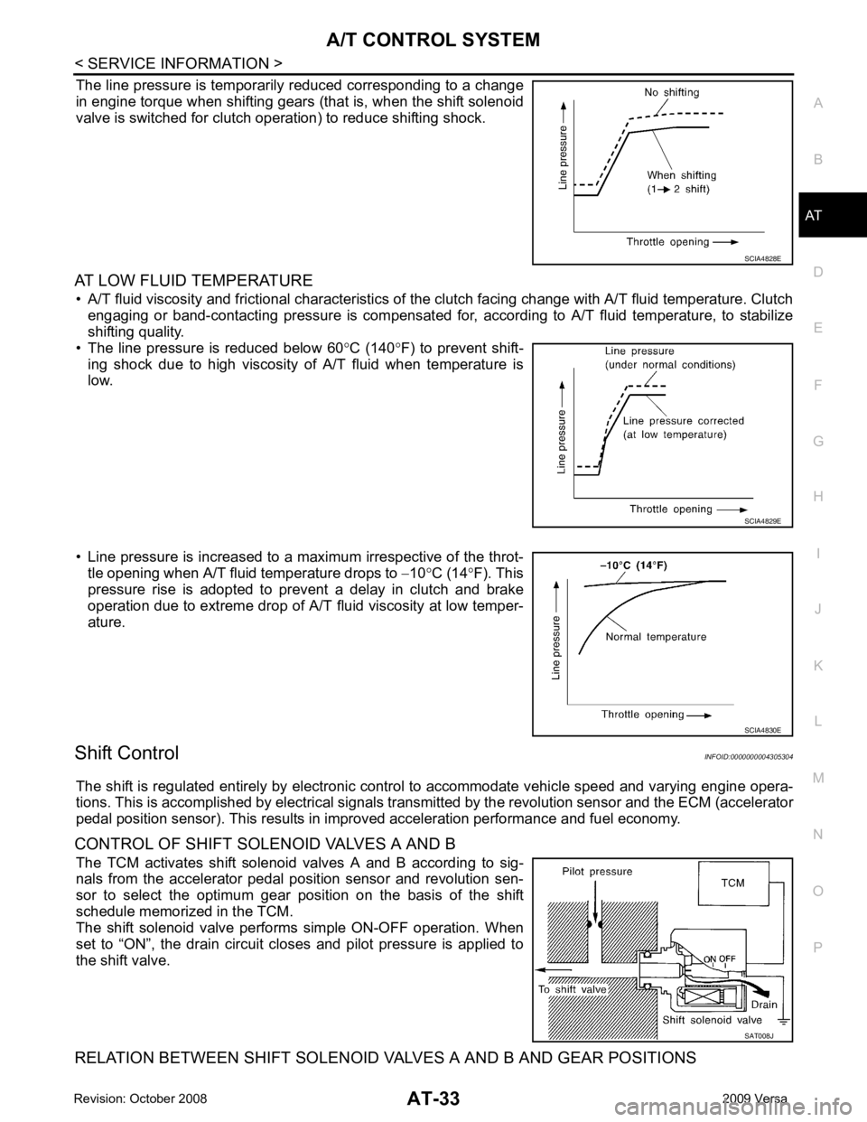
The line pressure is temporarily reduced corresponding to a change
in engine torque when shifting gears (that is, when the shift solenoid
valve is switched for clutch operation) to reduce shifting shock.
AT LOW FLUID TEMPERATURE • A/T fluid viscosity and frictional characteristics of t he clutch facing change with A/T fluid temperature. Clutch
engaging or band-contacting pressure is compensated for, according to A/T fluid temperature, to stabilize
shifting quality.
• The line pressure is reduced below 60 °C (140 °F) to prevent shift-
ing shock due to high viscosity of A/T fluid when temperature is
low.
• Line pressure is increased to a maximum irrespective of the throt- tle opening when A/T fluid temperature drops to −10 °C (14 °F). This
pressure rise is adopted to prevent a delay in clutch and brake
operation due to extreme drop of A/T fluid viscosity at low temper-
ature.
Shift Control INFOID:0000000004305304
The shift is regulated entirely by electronic cont rol to accommodate vehicle speed and varying engine opera-
tions. This is accomplished by electrical signals trans mitted by the revolution sensor and the ECM (accelerator
pedal position sensor). This results in improved acceleration performance and fuel economy.
CONTROL OF SHIFT SOLENOID VALVES A AND B The TCM activates shift solenoid valves A and B according to sig-
nals from the accelerator pedal position sensor and revolution sen-
sor to select the optimum gear pos ition on the basis of the shift
schedule memorized in the TCM.
The shift solenoid valve performs simple ON-OFF operation. When
set to “ON”, the drain circuit closes and pilot pressure is applied to
the shift valve.
RELATION BETWEEN SHIFT SOLENOID VALVES A AND B AND GEAR POSITIONS SAT008J
Page 1303 of 4331
DI
N
O P
CONTENTS
DRIVER INFORMATION SYSTEM
SERVICE INFORMATION .. ..........................2
PRECAUTION ................................................ .....2
Precaution for Supplemental Restraint System
(SRS) "AIR BAG" and "SEAT BELT PRE-TEN-
SIONER" ............................................................. ......
2
COMBINATION METERS .............................. .....3
Component Parts and Harness Connector Loca-
tion ...................................................................... ......
3
System Description ............................................. ......3
Arrangement of Combination Meter .................... ......5
Internal Circuit ..................................................... ......6
Wiring Diagram - METER - ................................. ......7
Combination Meter Harness Connector Terminal
Layout ................................................................. ......
9
Terminal and Reference Value for Combination
Meter ................................................................... ......
9
Self-Diagnosis Mode of Combination Meter ........ ....10
CONSULT-III Function (METER/M&A) ............... ....12
Trouble Diagnosis ............................................... ....13
Symptom Chart ................................................... ....14
Power Supply and Ground Circuit Inspection ..... ....14
Vehicle Speed Signal Inspection ......................... ....15
Engine Speed Signal Inspection ......................... ....16
Fuel Level Sensor Signal Inspection ................... ....16
Fuel Gauge Fluctuates, Indicates Wrong Value, or
Varies .................................................................. ....
18
Fuel Gauge Does Not Move to Full-position ...........18
DTC [U1000] CAN Communication Circuit ......... ....18
Electrical Component Inspection ......................... ....19
Removal and Installation .........................................19
WARNING LAMPS ......................................... ....20
Schematic ........................................................... ....20
Wiring Diagram - WARN - ................................... ....21 Oil Pressure Wa
rning Lamp Stays Off (Ignition
Switch ON) .......................................................... ....
29
Oil Pressure Wa rning Lamp Does Not Turn Off
(Oil Pressure Is Normal) ...................................... ....
31
Component Inspection ......................................... ....31
A/T INDICATOR ................................................ 33
System Description .............................................. ....33
Wiring Diagram - AT/IND - ................................... ....34
A/T Indicator Does Not Illuminate ........................ ....35
CVT INDICATOR ............................................... 37
System Description .............................................. ....37
Schematic ............................................................ ....37
Wiring Diagram - CVTIND - ................................. ....38
CVT Indicator Does Not Illuminate ...................... ....40
WARNING CHIME ............................................. 42
Component Parts and Harness Connector Loca-
tion ....................................................................... ....
42
System Description .............................................. ....42
Wiring Diagram - CHIME - ................................... ....45
Terminal and Reference Value for BCM ..................46
CONSULT-III Function (B CM) .................................46
Trouble Diagnosis ................................................ ....47
Combination Meter Buzzer Cir cuit Inspection .........48
Front Door Switch LH Signal Inspection .............. ....49
Key Switch Signal Inspec tion (Without Intelligent
Key) ..................................................................... ....
50
Key Switch and Ignition Knob Switch Signal In-
spection (With Intelligent Key, When Mechanical
Key Is Used) ........................................................ ....
51
Lighting Switch Signal Inspection ........................ ....53
Parking Brake Switch Signal Inspection .............. ....53
Electrical Component Inspection ......................... ....54
Page 1314 of 4331
![NISSAN LATIO 2009 Service Repair Manual CONSULT-III display Malfunction Reference page
CAN COMM CIRC [U1000] Malfunction is detected in CAN communication lines.
CAUTION:
Even when there is no malfunct ion on CAN communication system, mal-
f NISSAN LATIO 2009 Service Repair Manual CONSULT-III display Malfunction Reference page
CAN COMM CIRC [U1000] Malfunction is detected in CAN communication lines.
CAUTION:
Even when there is no malfunct ion on CAN communication system, mal-
f](/manual-img/5/57359/w960_57359-1313.png)
CONSULT-III display Malfunction Reference page
CAN COMM CIRC [U1000] Malfunction is detected in CAN communication lines.
CAUTION:
Even when there is no malfunct ion on CAN communication system, mal-
function may be misinterpreted when battery has low voltage (when main-
taining 7 - 8 V for about 2 seconds) or 10A fuse [No. 14, located in the fuse
block (J/B)] is removed. DI-18VEHICLE SPEED CIRC [B2205]
Malfunction is detected when an erroneous speed signal is input.
CAUTION:
Even when there is no malfunction on speed signal system, malfunctions
may be misinterpreted when battery has low voltage (when maintaining 7
- 8 V for about 2 seconds). DI-15Display item [Unit]
MAIN
SIGNALS SELECTION
FROM MENU Contents
SPEED METER [km/h] X X The value of vehicle speed sign
al, which is input from ABS ac-
tuator and electric unit (control unit).
SPEED OUTPUT [km/h] X X The value of vehicle speed signal, which is transmitted to each
unit with CAN communication.
TACHO METER [rpm] X X The value of engine speed signal, which is input from ECM.
W TEMP METER [ °C] X X The value of engine coolant temperature signal, which is input
from ECM.
FUEL METER [lit.] X X The value, which processes a resistance signal from fuel
gauge.
DISTANCE [km] X X The value, which is calculated by vehicle speed signal from
ABS actuator and electric unit (con trol unit), fuel gauge and fuel
consumption signal from ECM.
FUEL W/L [ON/OFF] X X Indicates [ON/OFF] condition of low-fuel warning lamp.
C-ENG W/L [ON/OFF] X Indicates [ON/OFF] condition of malfunction indicator lamp
(MIL).
AIR PRES W/L X Indicates [ON/OFF] condition of low tire pressure warning lamp.
SEAT BELT W/L X Indicates [ON/OFF] condition of seat belt warning lamp.
BUZZER [ON/OFF] X X Indicates [ON/ OFF] condition of buzzer.
DOOR W/L [ON/OFF] X Indicates [ON/OFF] condition of door warning lamp.
HI-BEAM IND [ON/OFF] X Indicat es [ON/OFF] condition of high beam indicator lamp.
Page 1363 of 4331
EC
A
N
O P
Inspection ............................................................
..
500
ON-VEHICLE REPAIR .... ...........................502
EVAP CANISTER ........................................... ..502
Exploded View .................................................... ..502
Removal and Installation .......................................502
Inspection ............................................................ ..503
SERVICE DATA AND SPECIFICATIONS
(SDS) ......... ................................. ................504
SERVICE DATA AND SPECIFICATIONS
(SDS) .............................................................. ..504
Idle Speed ........................................................... ..504
Ignition Timing ..................................................... ..504
Calculated Load Value ........................................ ..504
Mass Air Flow Sensor ......................................... ..504
MR TYPE 1
SERVICE INFOMATION .. ..........................505
APPLICATION NOTICE ................................. ..505
How to Check Vehicle Type ................................ ..505
INDEX FOR DTC ............................................ ..506
U1000-U1010 ...................................................... ..506
P0011-P0075 ...................................................... ..506
P0101-P0128 ...................................................... ..506
P0130-P0183 ...................................................... ..507
P0222-P0420 ...................................................... ..507
P0441-P0463 ...................................................... ..508
P0500-P0643 ...................................................... ..508
P0705-P0734 ...................................................... ..508
P0740-P0845 ...................................................... ..509
P0850-P1574 ...................................................... ..509
P1610-P1615 ...................................................... ..510
P1705-P1805 ...................................................... ..510
P2100-P2A00 ...................................................... ..510
PRECAUTIONS .............................................. ..512
Precaution for Supplemental Restraint System
(SRS) "AIR BAG" and "SEAT BELT PRE-TEN-
SIONER" ............................................................. ..
512
Precaution for Procedure without Cowl Top Cover ..512
On Board Diagnosis (OBD) System of Engine and
A/T, CVT ............................................................. ..
512
Precaution ........................................................... ..513
PREPARATION .............................................. ..516
Special Service Tool ........................................... ..516
Commercial Service Tool .................................... ..516
ENGINE CONTROL SYSTEM ........................ ..518
Schematic ........................................................... ..518
Multiport Fuel Injection (MFI) System ................. ..518
Electronic Ignition (EI) System ............................ ..521
Fuel Cut Control (at No Load and High Engine
Speed) ................................................................. ..
521
AIR CONDITIONING CUT CONTROL ........... ..523 Input/Output Signal Chart ....................................
..523
System Description .............................................. ..523
AUTOMATIC SPEED CONTROL DEVICE
(ASCD) ............................................................ 524
System Description .............................................. ..524
Component Description ....................................... ..525
CAN COMMUNICATION ................................. 526
System Description .............................................. ..526
EVAPORATIVE EMISSION SYSTEM ............. 527
Description ........................................................... ..527
Component Inspection ......................................... ..529
Removal and Installation ..................................... ..531
How to Detect Fuel Vapor Leakage ..................... ..531
ON BOARD REFUELING VAPOR RECOV-
ERY (ORVR) .................................................... 533
System Description .............................................. ..533
Diagnosis Procedure ........................................... ..533
Component Inspection ......................................... ..535
POSITIVE CRANKCASE VENTILATION ....... 538
Description ........................................................... ..538
Component Inspection ......................................... ..538
NVIS (NISSAN VEHICLE IMMOBILIZER SYS-
TEM-NATS) ..................................................... 540
Description ........................................................... ..540
ON BOARD DIAGNOSTIC (OBD) SYSTEM .. 541
Introduction .......................................................... ..541
Two Trip Detection Logic ..................................... ..541
Emission-related Diagnostic Information ............. ..542
Malfunction Indicator Lamp (MIL) ..........................557
OBD System Operation Chart ............................. ..560
BASIC SERVICE PROCEDURE ..................... 566
Basic Inspection .................................................. ..566
Idle Speed and Ignition Timing Check ................. ..570
Procedure After Replacing ECM ......................... ..571
VIN Registration .................................................. ..572
Accelerator Pedal Released Position Learning ... ..572
Throttle Valve Closed Position Learning ............. ..572
Idle Air Volume Learning ..................................... ..572
Fuel Pressure Check ........................................... ..574
TROUBLE DIAGNOSIS .................................. 577
Trouble Diagnosis Introduction ............................ ..577
DTC Inspection Priority Chart .............................. ..581
Fail-Safe Chart .................................................... ..582
Symptom Matrix Chart ......................................... ..583
Engine Control Component Parts Location ......... ..588
Vacuum Hose Drawing ........................................ ..594
Circuit Diagram .................................................... ..595
ECM Harness Connector Terminal Layout .......... ..597
ECM Terminal and Reference Value ................... ..597
CONSULT-III Function (ENGINE) ....................... ..604
Generic Scan Tool (GST) Function ..................... ..612
Page 1367 of 4331
EC
A
N
O P
Wiring Diagram ...................................................
..
818
Diagnosis Procedure ........................................... ..819
Component Inspection ........................................ ..821
DTC P0448 EVAP CANISTER VENT CON-
TROL VALVE ................................................. ..823
Component Description ....................................... ..823
CONSULT-III Refe rence Value in Data Monitor
Mode ................................................................... ..
823
On Board Diagnosis Logic .................................. ..823
DTC Confirmation Procedure .............................. ..823
Wiring Diagram ................................................... ..825
Diagnosis Procedure ........................................... ..826
Component Inspection ........................................ ..827
DTC P0451 EVAP CONTROL SYSTEM
PRESSURE SENSO R .................................... ..829
Component Description ....................................... ..829
CONSULT-III Refe rence Value in Data Monitor
Mode ................................................................... ..
829
On Board Diagnosis Logic .................................. ..829
DTC Confirmation Procedure .............................. ..829
Diagnosis Procedure ........................................... ..830
Component Inspection ........................................ ..831
DTC P0452 EVAP CONTROL SYSTEM
PRESSURE SENSO R .................................... ..
832
Component Description ....................................... ..832
CONSULT-III Refe rence Value in Data Monitor
Mode ................................................................... ..
832
On Board Diagnosis Logic .................................. ..832
DTC Confirmation Procedure .............................. ..832
Wiring Diagram ................................................... ..834
Diagnosis Procedure ........................................... ..835
Component Inspection ........................................ ..838
DTC P0453 EVAP CONTROL SYSTEM
PRESSURE SENSO R .................................... ..839
Component Description ....................................... ..839
CONSULT-III Refe rence Value in Data Monitor
Mode ................................................................... ..
839
On Board Diagnosis Logic .................................. ..839
DTC Confirmation Procedure .............................. ..839
Wiring Diagram ................................................... ..841
Diagnosis Procedure ........................................... ..842
Component Inspection ........................................ ..846
DTC P0455 EVAP CONTROL SYSTEM ........ ..847
On Board Diagnosis Logic .................................. ..847
DTC Confirmation Procedure .............................. ..847
Diagnosis Procedure ........................................... ..848
DTC P0456 EVAP CONTROL SYSTEM ........ ..853
On Board Diagnosis Logic .................................. ..853
DTC Confirmation Procedure .............................. ..854
Overall Function Check ....................................... ..854
Diagnosis Procedure ........................................... ..855
DTC P0460 FUEL LEVEL SENSOR .............. ..860
Component Description ....................................... ..860 On Board Diagnosis Logic ...................................
..860
DTC Confirmation Procedure .............................. ..860
Diagnosis Procedure ........................................... ..860
Removal and Installation ..................................... ..861
DTC P0461 FUEL LEVEL SENSOR ............... 862
Component Description ....................................... ..862
On Board Diagnosis Logic ................................... ..862
Overall Function Check ....................................... ..862
Diagnosis Procedure ........................................... ..863
Removal and Installation ..................................... ..863
DTC P0462, P0463 FUEL LEVEL SENSOR .. 864
Component Description ....................................... ..864
On Board Diagnosis Logic ................................... ..864
DTC Confirmation Procedure .............................. ..864
Diagnosis Procedure ........................................... ..864
Removal and Installation ..................................... ..865
DTC P0500 VSS .............................................. 866
Description ........................................................... ..866
On Board Diagnosis Logic ................................... ..866
DTC Confirmation Procedure .............................. ..866
Overall Function Check ....................................... ..867
Diagnosis Procedure ........................................... ..867
DTC P0506 ISC SYSTEM ............................... 868
Description ........................................................... ..868
On Board Diagnosis Logic ................................... ..868
DTC Confirmation Procedure .............................. ..868
Diagnosis Procedure ........................................... ..868
DTC P0507 ISC SYSTEM ............................... 870
Description ........................................................... ..870
On Board Diagnosis Logic ................................... ..870
DTC Confirmation Procedure .............................. ..870
Diagnosis Procedure ........................................... ..870
DTC P0605 ECM ............................................. 872
Component Description ....................................... ..872
On Board Diagnosis Logic ................................... ..872
DTC Confirmation Procedure .............................. ..872
Diagnosis Procedure ........................................... ..873
DTC P0643 SENSOR POWER SUPPLY ........ 874
On Board Diagnosis Logic ................................... ..874
DTC Confirmation Procedure .............................. ..874
Wiring Diagram .................................................... ..875
Diagnosis Procedure ........................................... ..876
DTC P0850 PNP SWITCH .............................. 879
Component Description ....................................... ..879
CONSULT-III Reference Va lue in Data Monitor
Mode .................................................................... ..
879
On Board Diagnosis Logic ................................... ..879
DTC Confirmation Procedure .............................. ..879
Overall Function Check ....................................... ..880
Wiring Diagram .................................................... ..881
Diagnosis Procedure ........................................... ..882
DTC P1148 CLOSED LOOP CONTROL ........ 885
Page 1369 of 4331
EC
A
N
O P
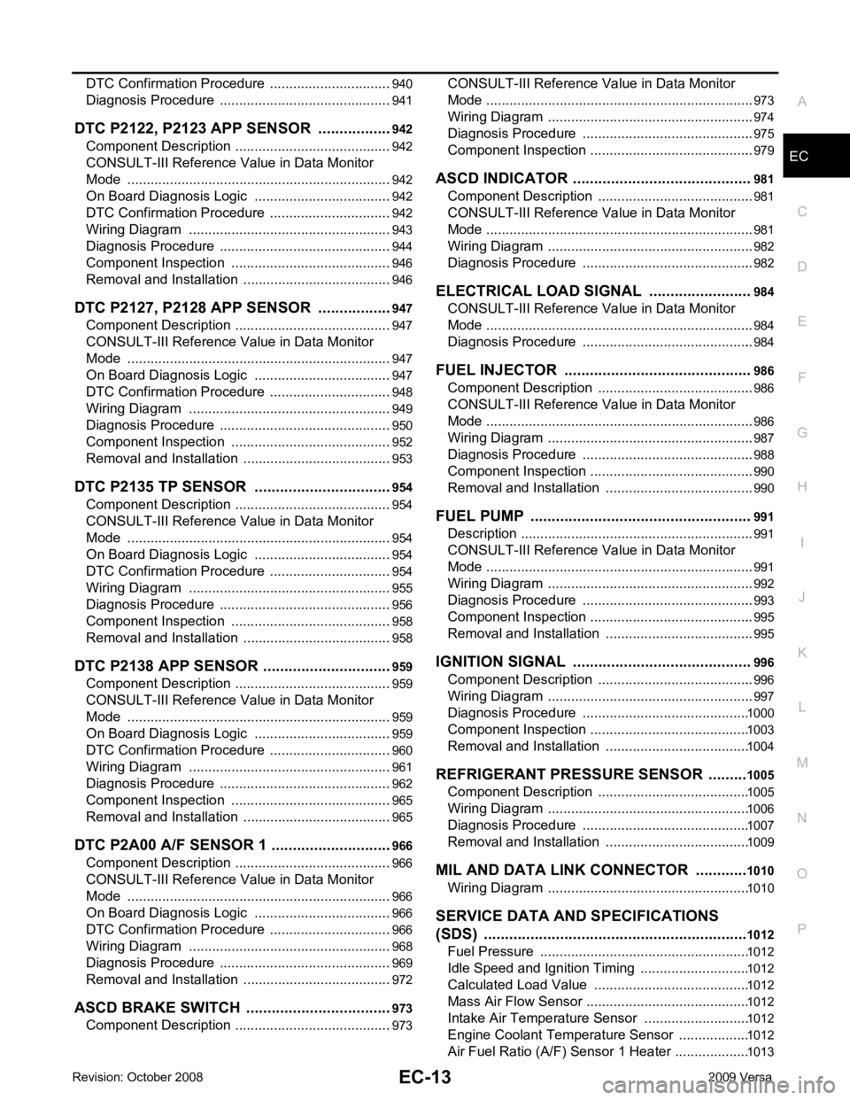
DTC Confirmation Procedure ..............................
..
940
Diagnosis Procedure ........................................... ..941
DTC P2122, P2123 APP SENSOR ................ ..942
Component Description ....................................... ..942
CONSULT-III Refe rence Value in Data Monitor
Mode ................................................................... ..
942
On Board Diagnosis Logic .................................. ..942
DTC Confirmation Procedure .............................. ..942
Wiring Diagram ................................................... ..943
Diagnosis Procedure ........................................... ..944
Component Inspection ........................................ ..946
Removal and Installation .......................................946
DTC P2127, P2128 APP SENSOR ................ ..947
Component Description ....................................... ..947
CONSULT-III Refe rence Value in Data Monitor
Mode ................................................................... ..
947
On Board Diagnosis Logic .................................. ..947
DTC Confirmation Procedure .............................. ..948
Wiring Diagram ................................................... ..949
Diagnosis Procedure ........................................... ..950
Component Inspection ........................................ ..952
Removal and Installation .......................................953
DTC P2135 TP SENSOR ............................... ..954
Component Description ....................................... ..954
CONSULT-III Refe rence Value in Data Monitor
Mode ................................................................... ..
954
On Board Diagnosis Logic .................................. ..954
DTC Confirmation Procedure .............................. ..954
Wiring Diagram ................................................... ..955
Diagnosis Procedure ........................................... ..956
Component Inspection ........................................ ..958
Removal and Installation .......................................958
DTC P2138 APP SENSOR ............................. ..959
Component Description ....................................... ..959
CONSULT-III Refe rence Value in Data Monitor
Mode ................................................................... ..
959
On Board Diagnosis Logic .................................. ..959
DTC Confirmation Procedure .............................. ..960
Wiring Diagram ................................................... ..961
Diagnosis Procedure ........................................... ..962
Component Inspection ........................................ ..965
Removal and Installation .......................................965
DTC P2A00 A/F SENSOR 1 ........................... ..966
Component Description ....................................... ..966
CONSULT-III Refe rence Value in Data Monitor
Mode ................................................................... ..
966
On Board Diagnosis Logic .................................. ..966
DTC Confirmation Procedure .............................. ..966
Wiring Diagram ................................................... ..968
Diagnosis Procedure ........................................... ..969
Removal and Installation .......................................972
ASCD BRAKE SWITCH ................................. ..973
Component Description ....................................... ..973 CONSULT-III Reference Va
lue in Data Monitor
Mode .................................................................... ..
973
Wiring Diagram .................................................... ..974
Diagnosis Procedure ........................................... ..975
Component Inspection ......................................... ..979
ASCD INDICATOR .......................................... 981
Component Description ....................................... ..981
CONSULT-III Reference Va lue in Data Monitor
Mode .................................................................... ..
981
Wiring Diagram .................................................... ..982
Diagnosis Procedure ........................................... ..982
ELECTRICAL LOAD SIGNAL ........................ 984
CONSULT-III Reference Va lue in Data Monitor
Mode .................................................................... ..
984
Diagnosis Procedure ........................................... ..984
FUEL INJECTOR ............................................ 986
Component Description ....................................... ..986
CONSULT-III Reference Va lue in Data Monitor
Mode .................................................................... ..
986
Wiring Diagram .................................................... ..987
Diagnosis Procedure ........................................... ..988
Component Inspection ......................................... ..990
Removal and Installation ..................................... ..990
FUEL PUMP .................................................... 991
Description ........................................................... ..991
CONSULT-III Reference Va lue in Data Monitor
Mode .................................................................... ..
991
Wiring Diagram .................................................... ..992
Diagnosis Procedure ........................................... ..993
Component Inspection ......................................... ..995
Removal and Installation ..................................... ..995
IGNITION SIGNAL .......................................... 996
Component Description ....................................... ..996
Wiring Diagram .................................................... ..997
Diagnosis Procedure ........................................... 1000
Component Inspection ......................................... 1003
Removal and Installation ..................................... 1004
REFRIGERANT PRESSURE SENSOR ......... 1005
Component Description ....................................... 1005
Wiring Diagram .................................................... 1006
Diagnosis Procedure ........................................... 1007
Removal and Installation ..................................... 1009
MIL AND DATA LINK CONNECTOR ............ 1010
Wiring Diagram .................................................... 1010
SERVICE DATA AND SPECIFICATIONS
(SDS) .............................................................. 1012
Fuel Pressure ...................................................... 1012
Idle Speed and Ignition Timing ............................ 1012
Calculated Load Value ........................................ 1012
Mass Air Flow Sensor .......................................... 1012
Intake Air Temperature Sensor ........................... 1012
Engine Coolant Temperature Sensor .................. 1012
Air Fuel Ratio (A/F) Sensor 1 Heater ................... 1013
Page 1377 of 4331
EC
A
N
O P
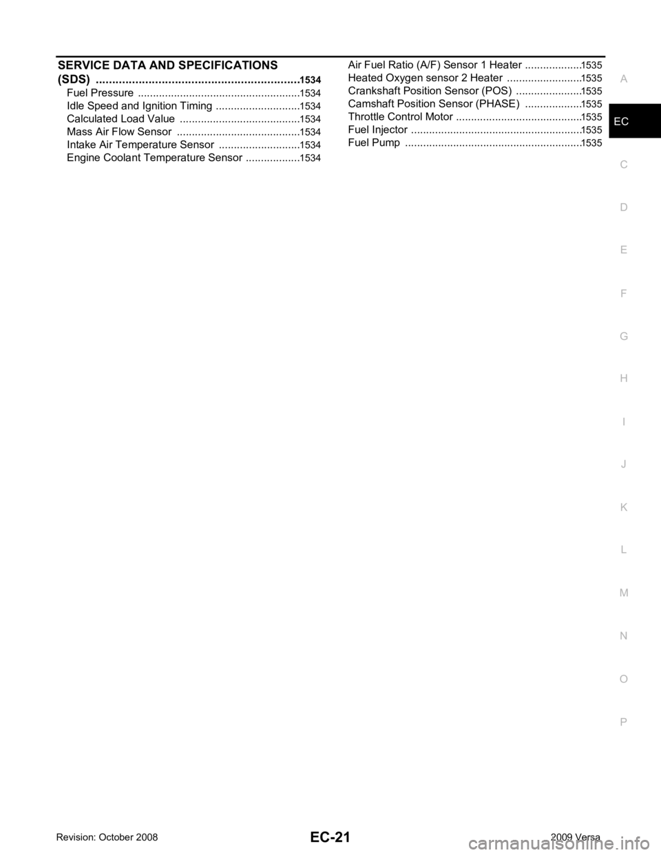
SERVICE DATA AND SPECIFICATIONS
(SDS) .............................................................. 1534
Fuel Pressure ...................................................... 1534
Idle Speed and Ignition Timing ............................ 1534
Calculated Load Value ........................................ 1534
Mass Air Flow Sensor ......................................... 1534
Intake Air Temperature Sensor ........................... 1534
Engine Coolant Temperature Sensor .................. 1534Air Fuel Ratio (A/F) Sensor 1 Heater ...................
1535
Heated Oxygen sensor 2 Heater ......................... 1535
Crankshaft Position Sensor (POS) ...................... 1535
Camshaft Position Sensor (PHASE) ................... 1535
Throttle Control Motor .......................................... 1535
Fuel Injector ......................................................... 1535
Fuel Pump ........................................................... 1535
Page 1397 of 4331
EC
NP
O
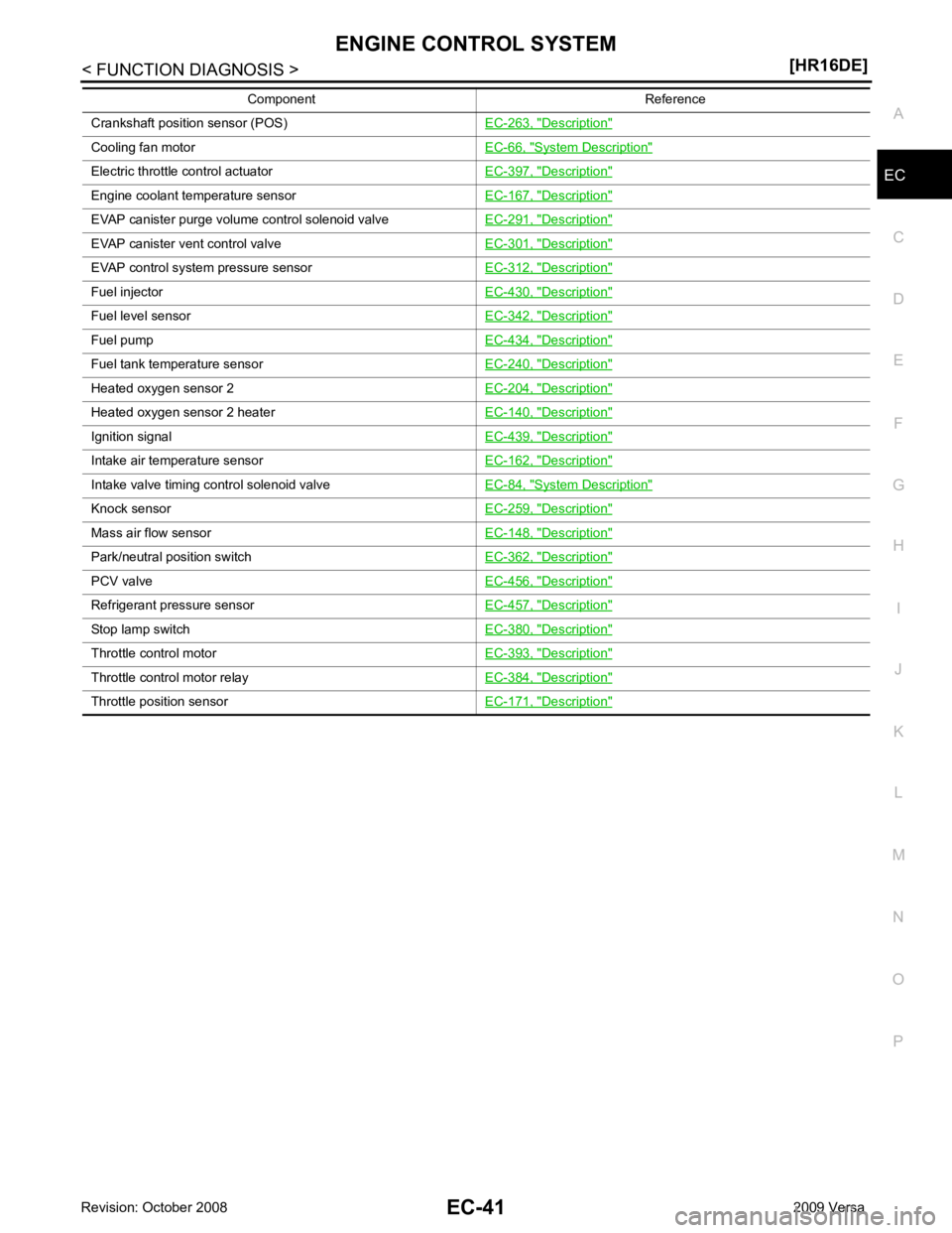
Crankshaft position sensor (POS)
EC-263, " Description "
Cooling fan motor
EC-66, " System Description "
Electric throttle control actuator
EC-397, " Description "
Engine coolant temperature sensor
EC-167, " Description "
EVAP canister purge volume control solenoid valve
EC-291, " Description "
EVAP canister vent control valve
EC-301, " Description "
EVAP control system pressure sensor
EC-312, " Description "
Fuel injector
EC-430, " Description "
Fuel level sensor
EC-342, " Description "
Fuel pump
EC-434, " Description "
Fuel tank temperature sensor
EC-240, " Description "
Heated oxygen sensor 2
EC-204, " Description "
Heated oxygen sensor 2 heater
EC-140, " Description "
Ignition signal
EC-439, " Description "
Intake air temperature sensor
EC-162, " Description "
Intake valve timing control solenoid valve
EC-84, " System Description "
Knock sensor
EC-259, " Description "
Mass air flow sensor
EC-148, " Description "
Park/neutral position switch
EC-362, " Description "
PCV valve
EC-456, " Description "
Refrigerant pressure sensor
EC-457, " Description "
Stop lamp switch
EC-380, " Description "
Throttle control motor
EC-393, " Description "
Throttle control motor relay
EC-384, " Description "
Throttle position sensor
EC-171, " Description "Component Reference