2009 NISSAN LATIO trunk release
[x] Cancel search: trunk releasePage 464 of 4331

BL
N
O P
Check Trunk Lid Opener S
witch Circuit (With Intel-
ligent Key) ........................................................... ..
212
Check Trunk Release Solenoid Circuit ............... ..214
FUEL FILLER LID OPENER .......................... ..217
Removal and Installation of Fuel Filler Lid Opener ..217
VEHICLE SECURITY (THEFT WARNING)
SYSTEM ......................................................... ..
218
Component Parts and Harness Connector Loca-
tion ...................................................................... ..
218
System Description ............................................. ..219
CAN Communication System Description ........... ..221
Schematic ........................................................... ..222
Wiring Diagram - VEHSEC - ............................... ..223
Terminal and Reference Value for BCM ............. ..227
Terminal and Re ference Value for Intelligent Key
Unit ...................................................................... ..
231
CONSULT-III Function (BCM) ............................. ..233
Trouble Diagnosis ............................................... ..235
Preliminary Check ............................................... ..235
Symptom Chart ................................................... ..237
Diagnosis Procedure 1 ........................................ ..238
Diagnosis Procedure 2 ........................................ ..241
Diagnosis Procedure 3 ........................................ ..242
Diagnosis Procedure 4 ........................................ ..242
Diagnosis Procedure 5 ........................................ ..242
Diagnosis Procedure 6 ........................................ ..242
Diagnosis Procedure 7 ........................................ ..242
Diagnosis Procedure 8 ........................................ ..244
Diagnosis Procedure 9 ........................................ ..245 NATS (Nissan Anti-Theft System) ................
248
Component Parts and Harness Connector Loca-
tion ....................................................................... ..
248
System Description .............................................. ..248
System Composition ............................................ ..249
ECM Re-communicating Function ....................... ..249
Wiring Diagram - NATS - ..................................... ..251
Terminal and Reference Value for BCM ................252
CONSULT-III Function ........................................ ..256
Trouble Diagnosis Procedure .............................. ..257
Trouble Diagnosis ................................................ ..259
Diagnosis Procedure 1 ........................................ ..260
Diagnosis Procedure 2 ........................................ ..262
Diagnosis Procedure 3 ........................................ ..263
Diagnosis Procedure 4 ........................................ ..264
Diagnosis Procedure 5 ........................................ ..265
Diagnosis Procedure 6 ........................................ ..266
How to Replace NATS Antenna Amp .................. ..266
BODY REPAIR ................................................ 267
Body Exterior Paint Color .................................... ..267
Body Component Parts ....................................... ..269
Corrosion Protection ............................................ ..274
Body Sealing ....................................................... ..278
Body Construction ............................................... ..284
Body Alignment ................................................... ..286
Handling Precaution for Plastics .......................... ..303
Precaution in Repairing High Strength Steel ....... ..307
Foam Repair ........................................................ ..310
Replacement Operation ....................................... ..313
Page 501 of 4331

BL-40< SERVICE INFORMATION >
POWER DOOR LOCK SYSTEM
43 5
R Back door switch Input OFF ON (open) 0V
OFF (closed) Ba ttery voltage
44 5
LG Rear wiper auto stop Input ON Rear wiper operating 0
Rear wiper stopped Battery
45 7
GR Lock switch Input OFF ON (lock) 0V
OFF Battery voltage
46 7
L Unlock switch Input OFF ON (unlock) 0V
OFF Battery voltage
47 BR Front door switch LH Input OFF ON (open) 0V
OFF (closed) Ba ttery voltage
48 O Rear door switch LH Input OFF ON (open) 0V
OFF (closed) Ba ttery voltage
49 P Luggage room lamp Output OFF Any door open (ON) 0V
All doors closed (OFF) Battery voltage
50 SB A/C indicator Output ON A/C OFF 0
A/C ON Battery voltage
53 5
RBack door lock assem-
bly (actuator) Output OFF Back door (open) Battery voltage
53 6
RTrunk lamp switch and
trunk release solenoid Output OFF Trunk lid (open) Battery voltage
55 5
VRear wiper motor out-
put Output ONOFF 0
ON Battery voltage
56 R Battery saver output Output OFF
30 minutes after ignition
switch is turned OFF 0V
ON — Battery voltage
57 LG Battery power supply Input OFF — Battery voltage
59 7
GFront door lock actua-
tor LH (unlock) Output OFFOFF (neutral) 0V
ON (unlock) Battery voltage
60 V Turn signal (left) Output ON Turn left ON
61 W Turn signal (right) Output ON Turn right ON
63 BR Interior room lamp Output OFF Any door
switch ON (open) 0V
OFF (closed) Battery voltage
Terminal
Wire
color Signal name Signal
input/
output Measuring condition
Reference value or waveform
(Approx.)
Ignition
switch Operation or condition SKIA3009J
SKIA3009J
Page 529 of 4331

BL-68< SERVICE INFORMATION >
REMOTE KEYLESS ENTRY SYSTEM
43 5
R Back door switch Input OFF ON (open) 0V
OFF (closed) Ba ttery voltage
44 5
LG Rear wiper auto stop Input ON Rear wiper operating 0
Rear wiper stopped Battery
45 7
GR Lock switch Input OFF ON (lock) 0V
OFF Battery voltage
46 7
L Unlock switch Input OFF ON (unlock) 0V
OFF Battery voltage
47 BR Front door switch LH Input OFF ON (open) 0V
OFF (closed) Ba ttery voltage
48 O Rear door switch LH Input OFF ON (open) 0V
OFF (closed) Ba ttery voltage
49 P Luggage room lamp Output OFF Any door open (ON) 0V
All doors closed (OFF) Battery voltage
50 SB A/C indicator Output ON A/C OFF 0
A/C ON Battery voltage
53 5
RBack door lock assem-
bly (actuator) Output OFF Back door (open) Battery voltage
53 6
RTrunk lamp switch and
trunk release solenoid Output OFF Trunk lid (open) Battery voltage
55 5
VRear wiper motor out-
put Output ONOFF 0
ON Battery voltage
56 R Battery saver output Output OFF
30 minutes after ignition
switch is turned OFF 0V
ON — Battery voltage
57 LG Battery power supply Input OFF — Battery voltage
59 7
GFront door lock actua-
tor LH (unlock) Output OFFOFF (neutral) 0V
ON (unlock) Battery voltage
60 V Turn signal (left) Output ON Turn left ON
61 W Turn signal (right) Output ON Turn right ON
63 BR Interior room lamp Output OFF Any door
switch ON (open) 0V
OFF (closed) Battery voltage
Terminal
Wire
color Signal name Signal
input/
output Measuring condition
Reference value or waveform
(Approx.)
Ignition
switch Operation or condition SKIA3009J
SKIA3009J
Page 570 of 4331

BL
N
O P
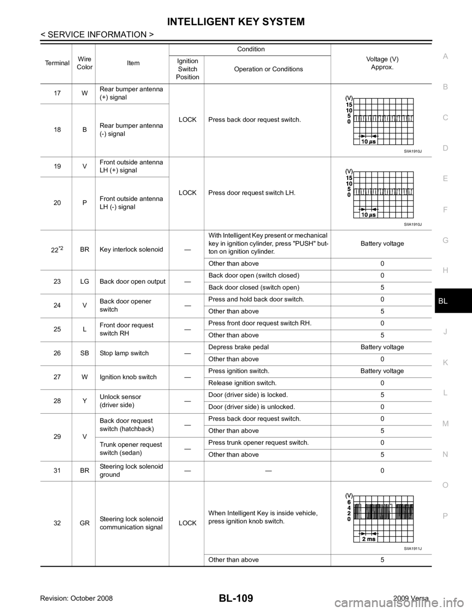
17 W
Rear bumper antenna
(+) signal
LOCK Press back door request switch.
18 B Rear bumper antenna
(-) signal
19 V Front outside antenna
LH (+) signal
LOCK Press door request switch LH.
20 P Front outside antenna
LH (-) signal
22 *2
BR Key interlock solenoid — With Intelligent Key present or mechanical
key in ignition cylinder, press "PUSH" but-
ton on ignition cylinder. Battery voltage
Other than above 0
23 LG Back door open output — Back door open (switch closed) 0
Back door closed (switch open) 5
24 V Back door opener
switch —Press and hold back door switch. 0
Other than above 5
25 L Front door request
switch RH —Press front door request switch RH. 0
Other than above 5
26 SB Stop lamp switch — Depress brake pedal Battery voltage
Other than above 0
27 W Ignition knob switch — Press ignition switch. Battery voltage
Release ignition switch. 0
28 Y Unlock sensor
(driver side) —Door (driver si
de) is locked. 5
Door (driver side ) is unlocked. 0
29 V Back door request
switch (hatchback) —Press back door request switch. 0
Other than above 5
Trunk opener request
switch (sedan) —Press trunk opener request switch. 0
Other than above 5
31 BR Steering lock solenoid
ground — — 0
32 GR Steering lock solenoid
communication signal LOCKWhen Intelligent Key is inside vehicle,
press ignition knob switch.
Other than above 5
Terminal
Wire
Color Item Condition
Voltage (V)Approx.
Ignition
Switch
Position Operation or Conditions SIIA1911J
Page 575 of 4331

BL-114< SERVICE INFORMATION >
INTELLIGENT KEY SYSTEM
43 5
R Back door switch Input OFF ON (open) 0V
OFF (closed) Ba ttery voltage
44 5
LG Rear wiper auto stop Input ON Rear wiper operating 0
Rear wiper stopped Battery
45 7
GR Lock switch Input OFF ON (lock) 0V
OFF Battery voltage
46 7
L Unlock switch Input OFF ON (unlock) 0V
OFF Battery voltage
47 BR Front door switch LH Input OFF ON (open) 0V
OFF (closed) Ba ttery voltage
48 O Rear door switch LH Input OFF ON (open) 0V
OFF (closed) Ba ttery voltage
49 P Luggage room lamp Output OFF Any door open (ON) 0V
All doors closed (OFF) Battery voltage
50 SB A/C indicator Output ON A/C OFF 0
A/C ON Battery voltage
53 5
RBack door lock assem-
bly (actuator) Output OFF Back door (open) Battery voltage
53 6
RTrunk lamp switch and
trunk release solenoid Output OFF Trunk lid (open) Battery voltage
55 5
VRear wiper motor out-
put Output ONOFF 0
ON Battery voltage
56 R Battery saver output Output OFF
30 minutes after ignition
switch is turned OFF 0V
ON — Battery voltage
57 LG Battery power supply Input OFF — Battery voltage
59 7
GFront door lock actua-
tor LH (unlock) Output OFFOFF (neutral) 0V
ON (unlock) Battery voltage
60 V Turn signal (left) Output ON Turn left ON
61 W Turn signal (right) Output ON Turn right ON
63 BR Interior room lamp Output OFF Any door
switch ON (open) 0V
OFF (closed) Battery voltage
Terminal
Wire
color Signal name Signal
input/
output Measuring condition
Reference value or waveform
(Approx.)
Ignition
switch Operation or condition SKIA3009J
SKIA3009J
Page 599 of 4331

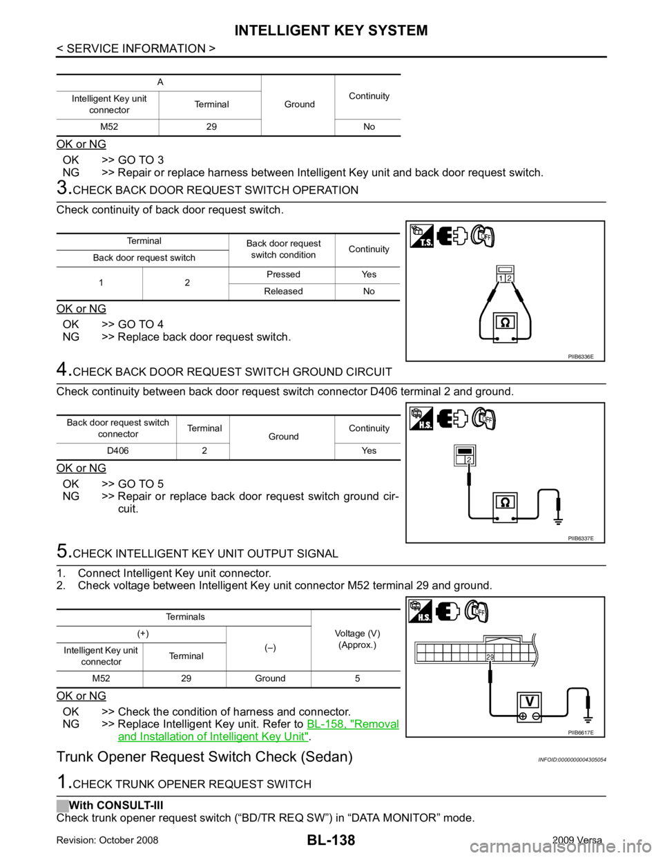
OK >> GO TO 3
NG >> Repair or replace harness between Intelligent Key unit and back door request switch. OK >> GO TO 4
NG >> Replace back door request switch. OK >> GO TO 5
NG >> Repair or replace back door request switch ground cir- cuit. OK >> Check the condition of harness and connector.
NG >> Replace Intelligent Key unit. Refer to BL-158, " Removal
and Installation of Intelligent Key Unit " .
Trunk Opener Request Switch Check (Sedan) INFOID:0000000004305054Terminal
Back door request
switch condition Continuity
Back door request switch
1 2 Pressed Yes
Released No
Page 600 of 4331

INTELLIGENT KEY SYSTEM
BL-139
< SERVICE INFORMATION >
C
D E
F
G H
J
K L
M A
B BL
N
O P
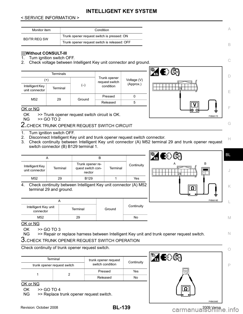
Without CONSULT-III
1. Turn ignition switch OFF.
2. Check voltage between Intelligent Key unit connector and ground.
OK or NG OK >> Trunk opener request switch circuit is OK.
NG >> GO TO 2 2.
CHECK TRUNK OPENER REQUEST SWITCH CIRCUIT
1. Turn ignition switch OFF.
2. Disconnect Intelligent Key unit and trunk opener request switch connector.
3. Check continuity between Intelligent Key unit connector (A) M52 terminal 29 and trunk opener request switch connector (B) B129 terminal 1.
4. Check continuity between Intelligent Key unit connector (A) M52 terminal 29 and ground.
OK or NG OK >> GO TO 3
NG >> Repair or replace harness between Intelligent Key unit and trunk opener request switch. 3.
CHECK TRUNK OPENER REQUEST SWITCH OPERATION
Check continuity of trunk opener request switch.
OK or NG OK >> GO TO 4
NG >> Replace trunk opener request switch. Monitor item Condition
BD/TR REQ SW Trunk opener request switch is pressed: ON
Trunk opener request switch is released: OFF Terminals
Trunk opener
request switch condition Voltage (V)
(Approx.)
(+)
(–)
Intelligent Key
unit connector Terminal
M52 29 Ground Pressed 0
Released 5 PIIB6617E
A B
Continuity
Intelligent Key
unit connector Terminal Trunk opener re-
quest switch con-
nector Terminal
M52 29 B129 1 Yes
A GroundContinuity
Intelligent Key unit
connector Terminal
M52 29 No PIIB6618E
Terminal
trunk opener request
switch condition Continuity
trunk opener request switch
1 2 Pressed Yes
Released No PIIB6336E
Page 639 of 4331

BL-178< SERVICE INFORMATION >
BACK DOOR LOCK
43 5
R Back door switch Input OFF ON (open) 0V
OFF (closed) Ba ttery voltage
44 5
LG Rear wiper auto stop Input ON Rear wiper operating 0
Rear wiper stopped Battery
45 7
GR Lock switch Input OFF ON (lock) 0V
OFF Battery voltage
46 7
L Unlock switch Input OFF ON (unlock) 0V
OFF Battery voltage
47 BR Front door switch LH Input OFF ON (open) 0V
OFF (closed) Ba ttery voltage
48 O Rear door switch LH Input OFF ON (open) 0V
OFF (closed) Ba ttery voltage
49 P Luggage room lamp Output OFF Any door open (ON) 0V
All doors closed (OFF) Battery voltage
50 SB A/C indicator Output ON A/C OFF 0
A/C ON Battery voltage
53 5
RBack door lock assem-
bly (actuator) Output OFF Back door (open) Battery voltage
53 6
RTrunk lamp switch and
trunk release solenoid Output OFF Trunk lid (open) Battery voltage
55 5
VRear wiper motor out-
put Output ONOFF 0
ON Battery voltage
56 R Battery saver output Output OFF
30 minutes after ignition
switch is turned OFF 0V
ON — Battery voltage
57 LG Battery power supply Input OFF — Battery voltage
59 7
GFront door lock actua-
tor LH (unlock) Output OFFOFF (neutral) 0V
ON (unlock) Battery voltage
60 V Turn signal (left) Output ON Turn left ON
61 W Turn signal (right) Output ON Turn right ON
63 BR Interior room lamp Output OFF Any door
switch ON (open) 0V
OFF (closed) Battery voltage
Terminal
Wire
color Signal name Signal
input/
output Measuring condition
Reference value or waveform
(Approx.)
Ignition
switch Operation or condition SKIA3009J
SKIA3009J