Page 691 of 4331

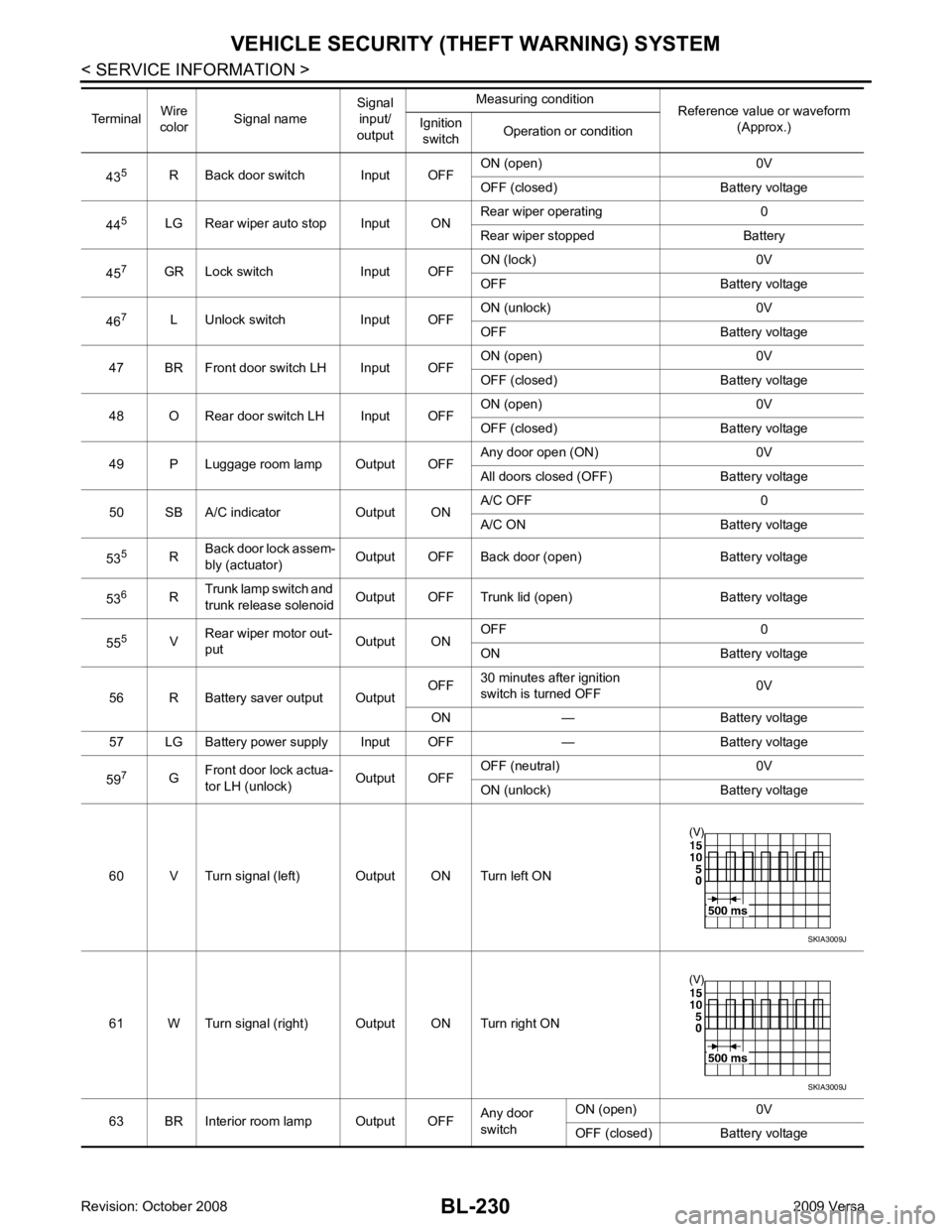
BL-230< SERVICE INFORMATION >
VEHICLE SECURITY (T
HEFT WARNING) SYSTEM
43 5
R Back door switch Input OFF ON (open) 0V
OFF (closed) Ba ttery voltage
44 5
LG Rear wiper auto stop Input ON Rear wiper operating 0
Rear wiper stopped Battery
45 7
GR Lock switch Input OFF ON (lock) 0V
OFF Battery voltage
46 7
L Unlock switch Input OFF ON (unlock) 0V
OFF Battery voltage
47 BR Front door switch LH Input OFF ON (open) 0V
OFF (closed) Ba ttery voltage
48 O Rear door switch LH Input OFF ON (open) 0V
OFF (closed) Ba ttery voltage
49 P Luggage room lamp Output OFF Any door open (ON) 0V
All doors closed (OFF) Battery voltage
50 SB A/C indicator Output ON A/C OFF 0
A/C ON Battery voltage
53 5
RBack door lock assem-
bly (actuator) Output OFF Back door (open) Battery voltage
53 6
RTrunk lamp switch and
trunk release solenoid Output OFF Trunk lid (open) Battery voltage
55 5
VRear wiper motor out-
put Output ONOFF 0
ON Battery voltage
56 R Battery saver output Output OFF
30 minutes after ignition
switch is turned OFF 0V
ON — Battery voltage
57 LG Battery power supply Input OFF — Battery voltage
59 7
GFront door lock actua-
tor LH (unlock) Output OFFOFF (neutral) 0V
ON (unlock) Battery voltage
60 V Turn signal (left) Output ON Turn left ON
61 W Turn signal (right) Output ON Turn right ON
63 BR Interior room lamp Output OFF Any door
switch ON (open) 0V
OFF (closed) Battery voltage
Terminal
Wire
color Signal name Signal
input/
output Measuring condition
Reference value or waveform
(Approx.)
Ignition
switch Operation or condition SKIA3009J
SKIA3009J
Page 705 of 4331

BL-244< SERVICE INFORMATION >
VEHICLE SECURITY (T
HEFT WARNING) SYSTEM
OK >> GO TO 3
NG >> Repair or replace harness. 3.
CHECK DOOR SWITCHES
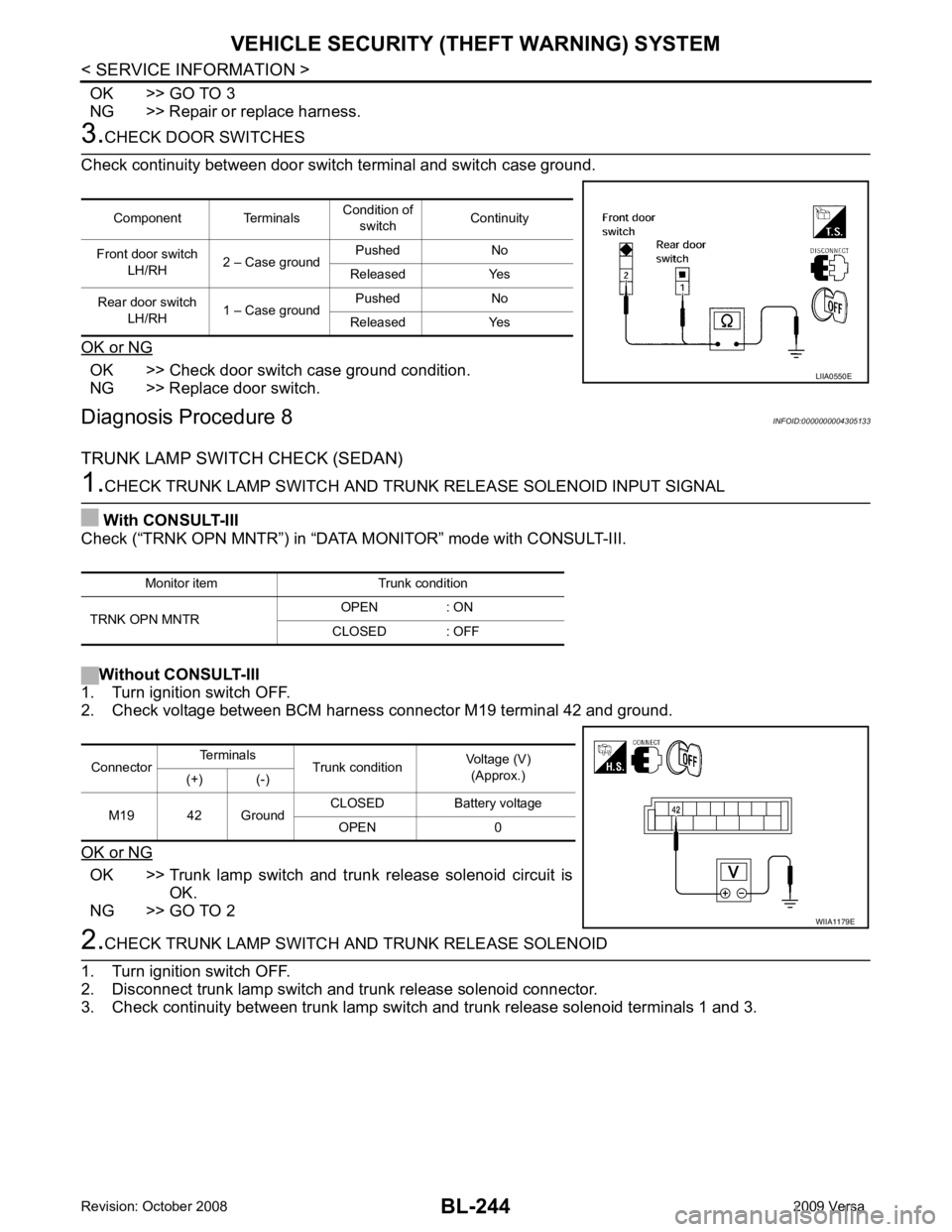
Check continuity between door switch terminal and switch case ground.
OK or NG OK >> Check door switch case ground condition.
NG >> Replace door switch.
Diagnosis Procedure 8 INFOID:0000000004305133
TRUNK LAMP SWITCH CHECK (SEDAN) 1.
CHECK TRUNK LAMP SWITCH AND TRUNK RELEASE SOLENOID INPUT SIGNAL
With CONSULT-III
Check (“TRNK OPN MNTR”) in “DATA MONITOR” mode with CONSULT-III.
Without CONSULT-III
1. Turn ignition switch OFF.
2. Check voltage between BCM harness connector M19 terminal 42 and ground.
OK or NG OK >> Trunk lamp switch and trunk release solenoid circuit is
OK.
NG >> GO TO 2 2.
CHECK TRUNK LAMP SWITCH A ND TRUNK RELEASE SOLENOID
1. Turn ignition switch OFF.
2. Disconnect trunk lamp switch and trunk release solenoid connector.
3. Check continuity between trunk lamp switch and trunk release solenoid terminals 1 and 3.
Component Terminals
Condition of
switch Continuity
Front door switch LH/RH 2 – Case ground Pushed No
Released Yes
Rear door switch LH/RH 1 – Case ground Pushed No
Released Yes LIIA0550E
Monitor item Trunk condition
TRNK OPN MNTR OPEN : ON
CLOSED : OFF Connector
Terminals
Trunk condition Voltage (V)
(Approx.)
(+) (-)
M19 42 Ground CLOSED Battery voltage
OPEN 0 WIIA1179E
Page 706 of 4331
BL
N
O P
OK or NG OK >> GO TO 3
NG >> Replace trunk lamp switch and trunk release solenoid. OK >> GO TO 4
NG >> Repair or replace harness between BCM and trunk room lamp switch. OK >> Check connection of harness and connector.
NG >> Repair or replace trunk lamp switch and trunk release solenoid ground circuit.
Diagnosis Procedure 9 INFOID:0000000004305134
TRUNK KEY CYLINDER SWITCH CHECK (SEDAN) 41, " CONSULT-III Function (BCM) " .
Terminals Trunk condition Continuity
1 3 CLOSED No
OPEN Yes
Page 716 of 4331

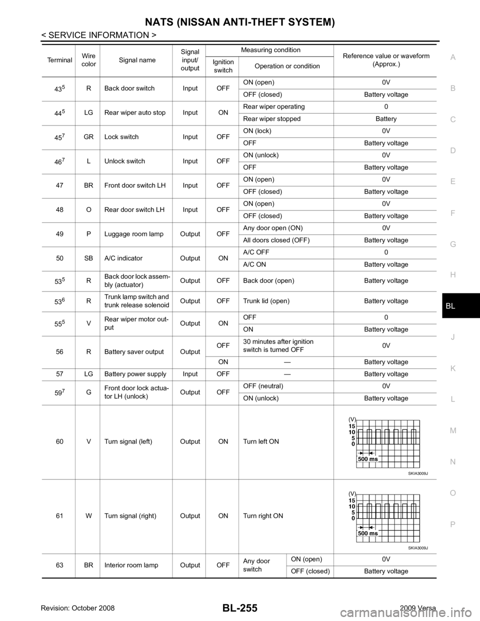
NATS (NISSAN ANTI-THEFT SYSTEM)
BL-255
< SERVICE INFORMATION >
C
D E
F
G H
J
K L
M A
B BL
N
O P
43
5
R Back door switch Input OFF ON (open) 0V
OFF (closed) Battery voltage
44 5
LG Rear wiper auto stop Input ON Rear wiper operating 0
Rear wiper stopped Battery
45 7
GR Lock switch Input OFF ON (lock) 0V
OFF Battery voltage
46 7
L Unlock switch Input OFF ON (unlock) 0V
OFF Battery voltage
47 BR Front door switch LH Input OFF ON (open) 0V
OFF (closed) Battery voltage
48 O Rear door switch LH Input OFF ON (open) 0V
OFF (closed) Battery voltage
49 P Luggage room lamp Output OFF Any door open (ON) 0V
All doors closed (OFF) Battery voltage
50 SB A/C indicator Output ON A/C OFF 0
A/C ON Battery voltage
53 5
RBack door lock assem-
bly (actuator) Output OFF Back door (open) Battery voltage
53 6
RTrunk lamp switch and
trunk release solenoid Output OFF Trunk lid (open) Battery voltage
55 5
VRear wiper motor out-
put Output ONOFF 0
ON Battery voltage
56 R Battery saver output Output OFF
30 minutes after ignition
switch is turned OFF 0V
ON — Battery voltage
57 LG Battery power supply Input OFF — Battery voltage
59 7
GFront door lock actua-
tor LH (unlock) Output OFFOFF (neutral) 0V
ON (unlock) Battery voltage
60 V Turn signal (left) Output ON Turn left ON
61 W Turn signal (right) Output ON Turn right ON
63 BR Interior room lamp Output OFF Any door
switch ON (open) 0V
OFF (closed) Battery voltage
Terminal
Wire
color Signal name Signal
input/
output Measuring condition
Reference value or waveform
(Approx.)
Ignition
switch Operation or condition SKIA3009J
SKIA3009J
Page 2910 of 4331
EI
N
O P
7. Pull the rear bumper fascia side outward and release the
bumper side bracket.
8. Remove rear bumper fascia upper clips and screws.
9. Release rear bumper upper retainer (1), then pull rear bumper fascia outward away from rear of vehicle.
10. Disconnect license lamp connector.
11. Remove energy absorbing foam and rear bumper reinforcement.
12. Remove the bumper side bracket (1) RH/LH. • : Vehicle front
INSTALLATION Installation is in the reverse order of removal.
Removal and Installation - Sedan INFOID:0000000004307217
REMOVAL 1. Open trunk lid.
2. Remove rear combination lamp RH/LH. Refer to LT-87, " Removal and Installation " .
3. Remove rear bumper fascia spring nuts and screws RH/LH.
4. Remove rear fender protector. Refer to EI-24, " Removal and Installation " .
5. Pull the rear bumper fascia side outward and release the bumper side bracket.
6. Remove rear bumper fascia upper clips and screws. LIIA2580E
Page 2922 of 4331
EI
N
O P
TRUNK LID FINISHER
Removal and Installation INFOID:0000000004307227
REMOVAL 1. Disconnect the negative battery terminal.
2. Open trunk lid, remove trunk lid finisher inner. Refer to EI-55 .
3. Remove trunk lid finisher outer nuts.
4. Release the clips, then pull trunk lid finisher outer away from trunk lid.
5. Disconnect trunk lid opener switch connector and tr unk opener request switch connector, then remove
trunk lid finisher outer.
INSTALLATION Installation is in the reverse order of removal. 1. Trunk lid finisher outer 2. Trunk lid opener switch connector 3. Trunk opener request switch connector
A. Clip C101
Page 2924 of 4331

EI
N
O P
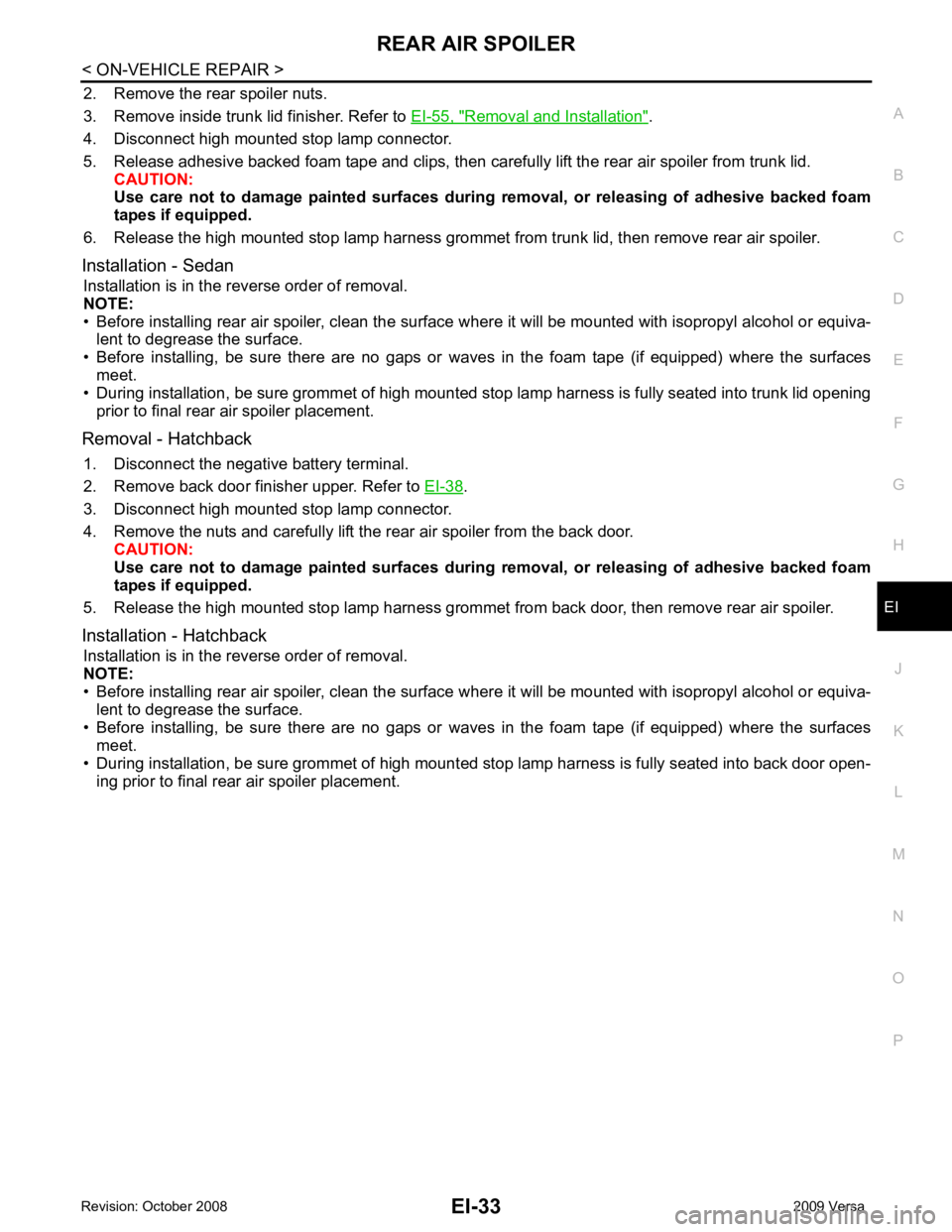
2. Remove the rear spoiler nuts.
3. Remove inside trunk lid finisher. Refer to EI-55, " Removal and Installation " .
4. Disconnect high mounted stop lamp connector.
5. Release adhesive backed foam tape and clips, then carefully lift the rear air spoiler from trunk lid. CAUTION:
Use care not to damage painted surfaces during removal, or releasing of adhesive backed foam
tapes if equipped.
6. Release the high mounted stop lamp harness grommet from trunk lid, then remove rear air spoiler.
Installation - Sedan Installation is in the reverse order of removal.
NOTE:
• Before installing rear air spoiler, clean the surface where it will be mounted with isopropyl alcohol or equiva-
lent to degrease the surface.
• Before installing, be sure there are no gaps or wa ves in the foam tape (if equipped) where the surfaces
meet.
• During installation, be sure grommet of high mounted stop lamp harness is fully seated into trunk lid opening
prior to final rear air spoiler placement.
Removal - Hatchback 1. Disconnect the negative battery terminal.
2. Remove back door finisher upper. Refer to EI-38 .
3. Disconnect high mounted stop lamp connector.
4. Remove the nuts and carefully lift the rear air spoiler from the back door. CAUTION:
Use care not to damage painted surfaces during removal, or releasing of adhesive backed foam
tapes if equipped.
5. Release the high mounted stop lamp harness grommet from back door, then remove rear air spoiler.
Installation - Hatchback Installation is in the reverse order of removal.
NOTE:
• Before installing rear air spoiler, clean the surface where it will be mounted with isopropyl alcohol or equiva-
lent to degrease the surface.
• Before installing, be sure there are no gaps or wa ves in the foam tape (if equipped) where the surfaces
meet.
• During installation, be sure grommet of high mount ed stop lamp harness is fully seated into back door open-
ing prior to final rear air spoiler placement.
Page 2946 of 4331
EI
N
O P
TRUNK ROOM TRIM & TRUNK LID FINISHER
Removal and Installation INFOID:0000000004307239
REMOVAL CAUTION:
• Insert a trim stick or suitable tool between panel on vehicle
and clips (as indicated with arrow) to release clips.
• Be careful not to damage the body while prying to release clips.
• Make sure clips are properly al igned in panel holes on body
when installing, then press them in completely.
1. Open trunk lid.
2. Position the rear seat cushion to the forward most position, then remove the rear seatback and seatback side RH/LH. Refer to
SE-15 .
3. Release the clips, then remove the seatback finisher RH/LH.
4. Lift and remove the trunk floor carpet. 1. Trunk side finisher RH 2. Seat back finisher RH (if equipped) 3. Trunk floor carpet
4. Seat back finisher LH (if equipped) 5. Trunk side finisher LH 6. Trunk rear plate
7. Trunk lid finisher inner A. Clip C205 ⇐Vehicle front