2009 NISSAN LATIO fuse box location
[x] Cancel search: fuse box locationPage 3322 of 4331
GW
N
O P
POWER WINDOW SYSTEM
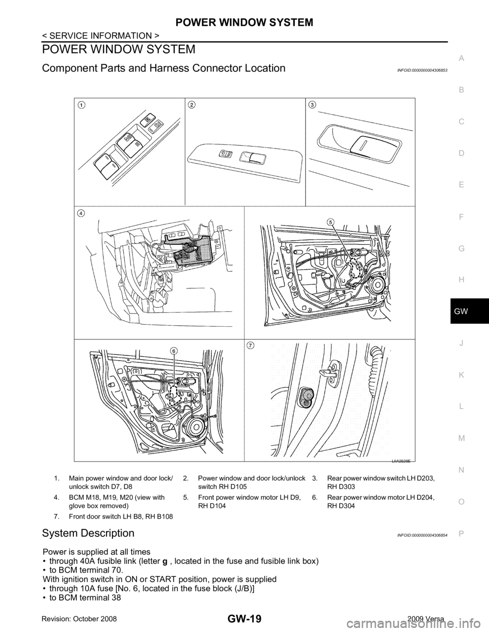
Component Parts and Har ness Connector Location INFOID:0000000004306853
System Description INFOID:0000000004306854
Power is supplied at all times
• through 40A fusible link (letter g , located in the fuse and fusible link box)
• to BCM terminal 70.
With ignition switch in ON or START position, power is supplied
• through 10A fuse [No. 6, located in the fuse block (J/B)]
• to BCM terminal 38 1. Main power window and door lock/
unlock switch D7, D8 2. Power window and door lock/unlock
switch RH D105 3. Rear power window switch LH D203,
RH D303
4. BCM M18, M19, M20 (view with glove box removed) 5. Front power window motor LH D9,
RH D104 6. Rear power window motor LH D204,
RH D304
7. Front door switch LH B8, RH B108
Page 3631 of 4331
LT
N
O P
HEADLAMP (FOR CANADA)
- DAYTIME LIGHT SYSTEM -
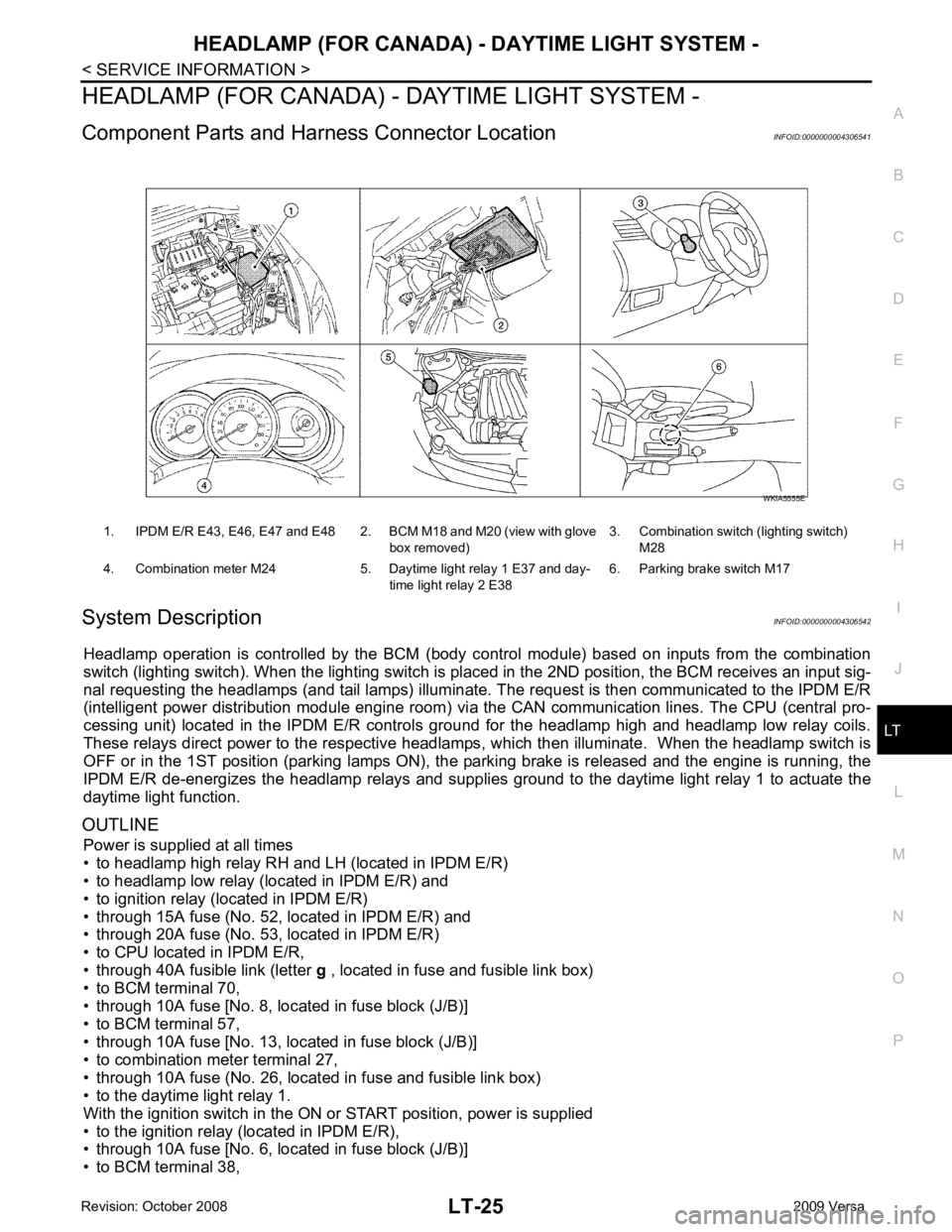
Component Parts and Har ness Connector Location INFOID:0000000004306541
System Description INFOID:0000000004306542
Headlamp operation is controlled by the BCM (body c ontrol module) based on inputs from the combination
switch (lighting switch). When the lighting switch is pl aced in the 2ND position, the BCM receives an input sig-
nal requesting the headlamps (and tail lamps) illuminate. The request is then communicated to the IPDM E/R
(intelligent power distribution module engine room) vi a the CAN communication lines. The CPU (central pro-
cessing unit) located in the IPDM E/R controls ground for the headlamp high and headlamp low relay coils.
These relays direct power to the respective headlamps , which then illuminate. When the headlamp switch is
OFF or in the 1ST position (parking lamps ON), the parking brake is released and the engine is running, the
IPDM E/R de-energizes the headlamp relays and supplies gr ound to the daytime light relay 1 to actuate the
daytime light function.
OUTLINE Power is supplied at all times
• to headlamp high relay RH and LH (located in IPDM E/R)
• to headlamp low relay (located in IPDM E/R) and
• to ignition relay (located in IPDM E/R)
• through 15A fuse (No. 52, located in IPDM E/R) and
• through 20A fuse (No. 53, located in IPDM E/R)
• to CPU located in IPDM E/R,
• through 40A fusible link (letter g , located in fuse and fusible link box)
• to BCM terminal 70,
• through 10A fuse [No. 8, located in fuse block (J/B)]
• to BCM terminal 57,
• through 10A fuse [No. 13, located in fuse block (J/B)]
• to combination meter terminal 27,
• through 10A fuse (No. 26, located in fuse and fusible link box)
• to the daytime light relay 1.
With the ignition switch in the ON or START position, power is supplied
• to the ignition relay (located in IPDM E/R),
• through 10A fuse [No. 6, located in fuse block (J/B)]
• to BCM terminal 38, 1. IPDM E/R E43, E46, E47 and E48 2. BCM M18 and M20 (view with glove
box removed)3. Combination switch (lighting switch)
M28
4. Combination meter M24 5. Daytime light relay 1 E37 and day- time light relay 2 E386. Parking brake switch M17
Page 3645 of 4331
LT
N
O P
FRONT FOG LAMP
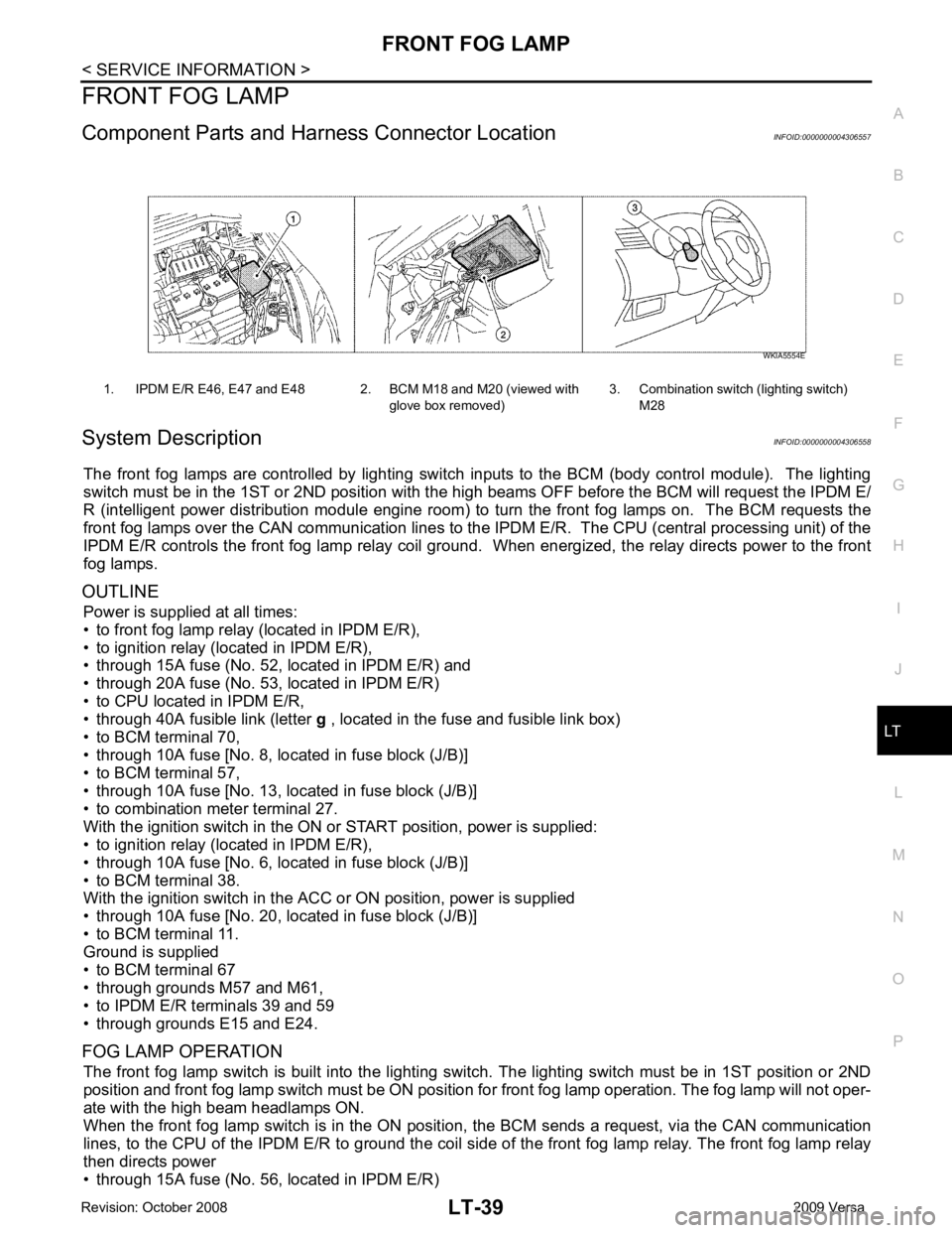
Component Parts and Har ness Connector Location INFOID:0000000004306557
System Description INFOID:0000000004306558
The front fog lamps are controlled by lighting switch inputs to the BCM (body control module). The lighting
switch must be in the 1ST or 2ND position with t he high beams OFF before the BCM will request the IPDM E/
R (intelligent power distribution module engine room) to turn the front fog lamps on. The BCM requests the
front fog lamps over the CAN communication lines to the IPDM E/R. The CPU (central processing unit) of the
IPDM E/R controls the front fog lamp relay coil ground. When energized, the relay directs power to the front
fog lamps.
OUTLINE Power is supplied at all times:
• to front fog lamp relay (located in IPDM E/R),
• to ignition relay (located in IPDM E/R),
• through 15A fuse (No. 52, located in IPDM E/R) and
• through 20A fuse (No. 53, located in IPDM E/R)
• to CPU located in IPDM E/R,
• through 40A fusible link (letter g , located in the fuse and fusible link box)
• to BCM terminal 70,
• through 10A fuse [No. 8, located in fuse block (J/B)]
• to BCM terminal 57,
• through 10A fuse [No. 13, located in fuse block (J/B)]
• to combination meter terminal 27.
With the ignition switch in the ON or START position, power is supplied:
• to ignition relay (located in IPDM E/R),
• through 10A fuse [No. 6, located in fuse block (J/B)]
• to BCM terminal 38.
With the ignition switch in the ACC or ON position, power is supplied
• through 10A fuse [No. 20, located in fuse block (J/B)]
• to BCM terminal 11.
Ground is supplied
• to BCM terminal 67
• through grounds M57 and M61,
• to IPDM E/R terminals 39 and 59
• through grounds E15 and E24.
FOG LAMP OPERATION The front fog lamp switch is built into the lighting s witch. The lighting switch must be in 1ST position or 2ND
position and front fog lamp switch must be ON position fo r front fog lamp operation. The fog lamp will not oper-
ate with the high beam headlamps ON.
When the front fog lamp switch is in the ON positi on, the BCM sends a request, via the CAN communication
lines, to the CPU of the IPDM E/R to ground the coil side of the front fog lamp relay. The front fog lamp relay
then directs power
• through 15A fuse (No. 56, located in IPDM E/R) 1. IPDM E/R E46, E47 and E48 2. BCM M18 and M20 (viewed with
glove box removed)3. Combination switch (lighting switch)
M28
Page 3679 of 4331
PARKING, LICENSE PL
ATE AND TAIL LAMPS
LT-73
< SERVICE INFORMATION >
C
D E
F
G H
I
J
L
M A
B LT
N
O P
PARKING, LICENSE PLATE AND TAIL LAMPS
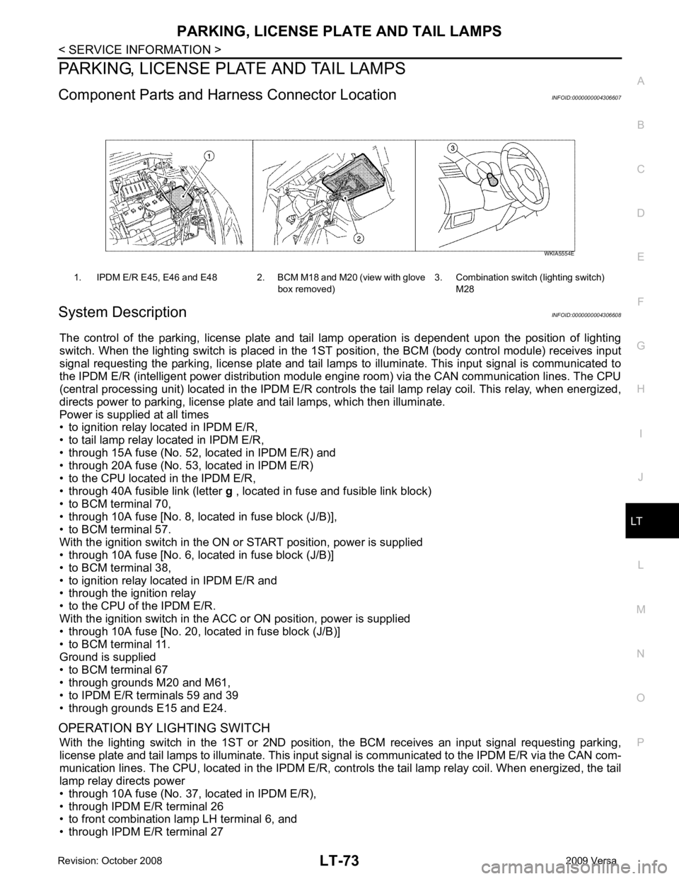
Component Parts and Har ness Connector Location INFOID:0000000004306607
System Description INFOID:0000000004306608
The control of the parking, license plate and tail lamp operation is dependent upon the position of lighting
switch. When the lighting switch is placed in the 1ST position, the BCM (body control module) receives input
signal requesting the parking, license plate and tail lamps to illuminate. This input signal is communicated to
the IPDM E/R (intelligent power distribution module engine room) via the CAN communication lines. The CPU
(central processing unit) located in the IPDM E/R contro ls the tail lamp relay coil. This relay, when energized,
directs power to parking, license plate and tail lamps, which then illuminate.
Power is supplied at all times
• to ignition relay located in IPDM E/R,
• to tail lamp relay located in IPDM E/R,
• through 15A fuse (No. 52, located in IPDM E/R) and
• through 20A fuse (No. 53, located in IPDM E/R)
• to the CPU located in the IPDM E/R,
• through 40A fusible link (letter g , located in fuse and fusible link block)
• to BCM terminal 70,
• through 10A fuse [No. 8, located in fuse block (J/B)],
• to BCM terminal 57.
With the ignition switch in the ON or START position, power is supplied
• through 10A fuse [No. 6, located in fuse block (J/B)]
• to BCM terminal 38,
• to ignition relay located in IPDM E/R and
• through the ignition relay
• to the CPU of the IPDM E/R.
With the ignition switch in the ACC or ON position, power is supplied
• through 10A fuse [No. 20, located in fuse block (J/B)]
• to BCM terminal 11.
Ground is supplied
• to BCM terminal 67
• through grounds M20 and M61,
• to IPDM E/R terminals 59 and 39
• through grounds E15 and E24.
OPERATION BY LIGHTING SWITCH With the lighting switch in the 1ST or 2ND positi on, the BCM receives an input signal requesting parking,
license plate and tail lamps to illuminate. This input si gnal is communicated to the IPDM E/R via the CAN com-
munication lines. The CPU, located in the IPDM E/R, c ontrols the tail lamp relay coil. When energized, the tail
lamp relay directs power
• through 10A fuse (No. 37, located in IPDM E/R),
• through IPDM E/R terminal 26
• to front combination lamp LH terminal 6, and
• through IPDM E/R terminal 27 1. IPDM E/R E45, E46 and E48 2. BCM M18 and M20 (view with glove
box removed)3. Combination switch (lighting switch)
M28 WKIA5554E
Page 3697 of 4331
LT
N
O P
INTERIOR ROOM LAMP
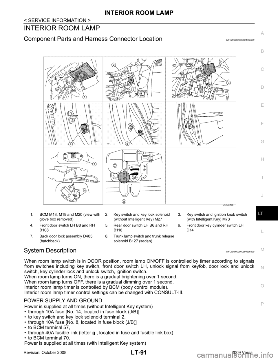
Component Parts and Har ness Connector Location INFOID:0000000004306628
System Description INFOID:0000000004306629
When room lamp switch is in DOOR position, room la mp ON/OFF is controlled by timer according to signals
from switches including key switch, front door switch LH, unlock signal from keyfob, door lock and unlock
switch, key cylinder lock and unlock switch, ignition switch.
When room lamp turns ON, there is a gradual brightening over 1 second.
When room lamp turns OFF, there is a gradual dimming over 1 second.
Interior room lamp timer is controlled by BCM (body control module).
Interior room lamp timer control settings can be changed with CONSULT-III.
POWER SUPPLY AND GROUND Power is supplied at all times (without Intelligent Key system)
• through 10A fuse [No. 14, located in fuse block (J/B)]
• to key switch and key lock solenoid terminal 2,
• through 10A fuse [No. 8, located in fuse block (J/B)]
• to BCM terminal 57,
• through 40A fusible link (letter g , located in fuse and fusible link box)
• to BCM terminal 70.
Power is supplied at all times (with Intelligent Key system) 1. BCM M18, M19 and M20 (view with
glove box removed) 2. Key switch and key lock solenoid
(without Intelligent Key) M27 3. Key switch and ignition knob switch
(with Intelligent Key) M73
4. Front door switch LH B8 and RH B108 5. Rear door switch LH B6 and RH
B116 6. Front door key cylinder switch LH
D14
7. Back door lock assembly D405 (hatchback) 8. Trunk lamp switch and trunk release
solenoid B127 (sedan)
Page 3984 of 4331

PG
N
O P
CONTENTS
POWER SUPPLY, GROUND & CIRCUIT ELEMENTS
SERVICE INFORMATION .. ..........................2
PRECAUTIONS .............................................. .....2
Precaution for Supplemental Restraint System
(SRS) "AIR BAG" and "SEAT BELT PRE-TEN-
SIONER" ............................................................. ......
2
POWER SUPPLY ROUTING CIRCUIT .......... .....3
Schematic ........................................................... ......3
Wiring Diagram - POWER - ................................ ......5
Fuse .................................................................... ....15
Fusible Link ......................................................... ....15
Circuit Breaker (Built Into BCM) .......................... ....15
Circuit Breaker .................................................... ....15
IPDM E/R (INTELLIGENT POWER DISTRI-
BUTION MODULE ENGINE ROOM) ............. ....16
System Description ............................................. ....16
CAN Communication System Description ........... ....17
Function of Detecting Igni tion Relay Malfunction ....17
CONSULT-III Function (IPDM E/R) ..................... ....17
Auto Active Test .................................................. ....19
IPDM E/R Terminal Arrangement - Type A ......... ....22
IPDM E/R Terminal Arrangement - Type B ......... ....23
Terminal and Reference Value for IPDM E/R ..... ....24
IPDM E/R Power/Ground Circuit Inspection ....... ....26
Inspection with CONSULT- III (Self-Diagnosis) .......27
Removal and Installation of IPDM E/R ....................27 GROUND CIRCUI
T ........................................... 29
Ground Distribution .............................................. ....29
HARNESS ................... ...................................... 38
Harness Layout ................................................... ....38
Wiring Diagram Codes (Cell Codes) ................... ....57
ELECTRICAL UNITS LOCATION .................... 60
Electrical Units Location ...................................... ....60
HARNESS CONNECTOR ................................. 64
Description ........................................................... ....64
ELECTRICAL UNITS ........................................ 67
Terminal Arrangement ......................................... ....67
STANDARDIZED RELAY ................................. 68
Description ........................................................... ....68
SUPER MULTIPLE JUNCTION (SMJ) ............. 70
Terminal Arrangement ......................................... ....70
FUSE BLOCK-JUNCTION BOX (J/B) .............. 72
Terminal Arrangement ......................................... ....72
FUSE AND FUSIBLE LINK BOX ...................... 73
Terminal Arrangement ......................................... ....73
Page 4092 of 4331
RF
N
O P
FUNCTION DIAGNOSIS
TROUBLE DIAGNOSIS
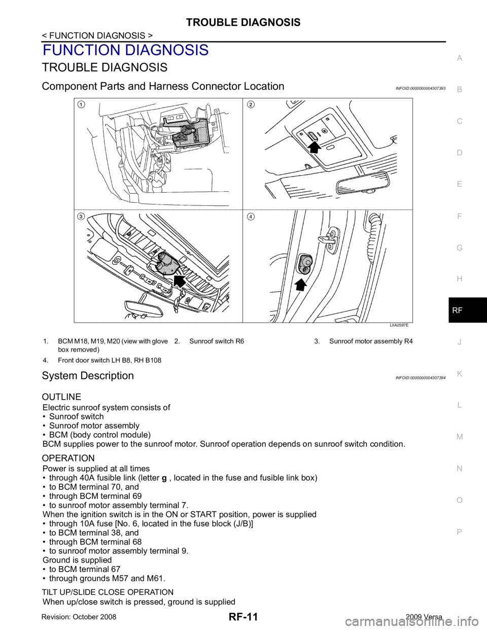
Component Parts and Har ness Connector Location INFOID:0000000004307393
System Description INFOID:0000000004307394
OUTLINE Electric sunroof system consists of
• Sunroof switch
• Sunroof motor assembly
• BCM (body control module)
BCM supplies power to the sunroof motor. S unroof operation depends on sunroof switch condition.
OPERATION Power is supplied at all times
• through 40A fusible link (letter g , located in the fuse and fusible link box)
• to BCM terminal 70, and
• through BCM terminal 69
• to sunroof motor assembly terminal 7.
When the ignition switch is in the ON or START position, power is supplied
• through 10A fuse [No. 6, located in the fuse block (J/B)]
• to BCM terminal 38, and
• through BCM terminal 68
• to sunroof motor assembly terminal 9.
Ground is supplied
• to BCM terminal 67
• through grounds M57 and M61.
TILT UP/SLIDE CLOSE OPERATION When up/close switch is pressed, ground is supplied
Page 4295 of 4331
WW
N
O P
FRONT WIPER AND WASHER SYSTEM
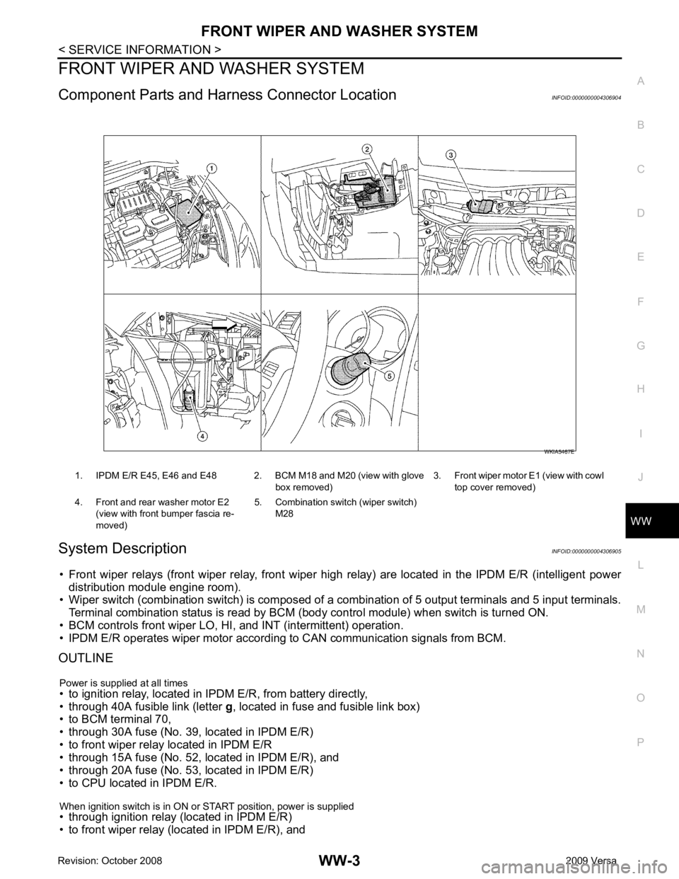
Component Parts and Har ness Connector Location INFOID:0000000004306904
System Description INFOID:0000000004306905
• Front wiper relays (front wiper relay, front wiper hi gh relay) are located in the IPDM E/R (intelligent power
distribution module engine room).
• Wiper switch (combination switch) is composed of a combination of 5 output terminals and 5 input terminals.
Terminal combination status is read by BCM (body control module) when switch is turned ON.
• BCM controls front wiper LO, HI, and INT (intermittent) operation.
• IPDM E/R operates wiper motor accordi ng to CAN communication signals from BCM.
OUTLINE
Power is supplied at all times
• to ignition relay, located in IPDM E/R, from battery directly,
• through 40A fusible link (letter g, located in fuse and fusible link box)
• to BCM terminal 70,
• through 30A fuse (No. 39, located in IPDM E/R)
• to front wiper relay located in IPDM E/R
• through 15A fuse (No. 52, located in IPDM E/R), and
• through 20A fuse (No. 53, located in IPDM E/R)
• to CPU located in IPDM E/R.
When ignition switch is in ON or START position, power is supplied
• through ignition relay (located in IPDM E/R)
• to front wiper relay (located in IPDM E/R), and 1. IPDM E/R E45, E46 and E48 2. BCM M18 and M20 (view with glove
box removed)3. Front wiper motor E1
(view with cowl
top cover removed)
4. Front and rear washer motor E2 (view with front bumper fascia re-
moved) 5. Combination switch (wiper switch)
M28