Page 770 of 4331

BL
N
O P
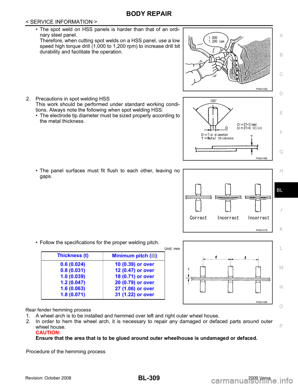
• The spot weld on HSS panels is harder than that of an ordi-
nary steel panel.
Therefore, when cutting spot welds on a HSS panel, use a low
speed high torque drill (1,000 to 1,200 rpm) to increase drill bit
durability and facilitate the operation.
2. Precautions in spot welding HSS This work should be performed under standard working condi-
tions. Always note the following when spot welding HSS:
• The electrode tip diameter must be sized properly according to the metal thickness.
• The panel surfaces must fit flush to each other, leaving no gaps.
• Follow the specifications for the proper welding pitch. Unit: mm
Rear fender hemming process 1. A wheel arch is to be installed and hemmed over left and right outer wheel house.
2. In order to hem the wheel arch, it is necessary to repair any damaged or defaced parts around outer
wheel house.
CAUTION:
Ensure that the area that is to be glued around outer wheelhouse is undamaged or defaced.
Procedure of the hemming process PIIA0146E
PIIA0147E
Page 864 of 4331
OK >> GO TO 2.
NG >> Repair or replace as necessary. YES >> GO TO 3.
NO >> Replace the wheel sensor. Refer to BRC-32, " Removal and Installation " .
.
Are tire pressure and size correct and is tire wear within specifications? YES >> GO TO 4.
NO >> Adjust tire pressure or replace tire(s). On-Vehicle Inspection and Service " or
RAX-5, " On-Vehi-
cle Inspection and Service " .
OK or NG OK >> GO TO 5.
NG >> Repair or replace as necessary. Refer to FAX-6, " Removal and Installation " or
RAX-5, " Removal
and Installation " .
OK >> GO TO 6.
NG >> Repair the circuit.
Page 927 of 4331
CO
NP
O
Except cool-
ing system
parts mal-
function — Overload on engine
Abusive driving
High engine rpm under no
load
Driving in low gear for ex-
tended time
Driving at extremely high
speed
Power train system mal-
function
—
Installed improper size
wheels and tires
Dragging brakes
Improper ignition timing
Blocked or restricted air
flow Blocked bumper Installed front bumper fas-
cia cover
—
Blocked radiator grille Mud contamination or paper
clogging
Blocked radiator Blocked air flow
Blocked condenser
Installed large fog lamp
Symptom Check items
Page 3080 of 4331
PREPARATION
EM-133
< SERVICE INFORMATION >
[MR18DE] C
D E
F
G H
I
J
K L
M A EM
NP
O
Valve guide reamer (1): Reaming valve guide inner hole
(2): Reaming hole for oversize valve guide
(J-43897-18)
(J-43897-12)
Oxygen sensor thread cleaner Reconditioning the exhaust system threads
before installing a new oxygen sensor (Use
with anti-seize lubricant shown below.)
a: J-43897-18 (18 mm dia.) for zirconia ox-
ygen sensor
b: J-43897-12 (12 mm dia.) for titania oxy-
gen sensor
Anti-seize lubricant (Permatex 133AR
or equivalent meeting MIL specifica-
tion MIL-A-907) Lubricating oxygen sensor thread cleaning
tool when reconditioning exhaust system
threads
E20 Torx® Socket
(J-45816) Removing and installing drive plate and fly-
wheel bolts
(Kent-Moore No.)
Tool name Description PBIC4013E
AEM488
AEM489
LBIA0285E
Page 3251 of 4331

SERVICE DATA AND SPECIFICATIONS (SDS)
FSU-17
< SERVICE INFORMATION >
C
D
F
G H
I
J
K L
M A
B FSU
N
O P
SERVICE DATA AND SPECIFICATIONS (SDS)
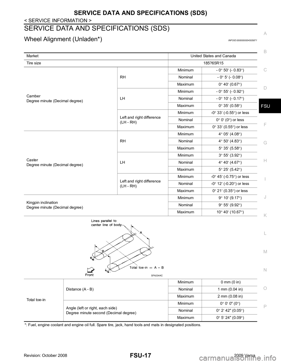
Wheel Alignment (Unladen*) INFOID:0000000004305871
*: Fuel, engine coolant and engine oil full. Spare tire, jack, hand tools and mats in designated positions. Market
United States and Canada
Tire size 185?65R15
Camber
Degree minute (Decimal degree) RH
Minimum - 0
° 50 ′ (- 0.83 °)
Nominal - 0 ° 5 ′ (- 0.08 °)
Maximum 0 ° 40 ′ (0.67 °)
LH Minimum - 0
° 55 ′ (- 0.92 °)
Nominal - 0 ° 10 ′ (- 0.17 °)
Maximum 0 ° 35 ′ (0.58 °)
Left and right difference
(LH - RH) Minimum -0
° 33 ′ (-0.55 °) or less
Nominal 0 ° 0 ′ (0 °) or less
Maximum 0 ° 33 ′ (0.55 °) or less
Caster
Degree minute (Decimal degree) RH
Minimum 4
° 05 ′ (4.08 °)
Nominal 4 ° 50 ′ (4.83 °)
Maximum 5 ° 35 ′ (5.58 °)
LH Minimum 3
°
55 ′ (3.92 °)
Nominal 4 ° 40 ′ (4.67 °)
Maximum 5 ° 25 ′ (5.42 °)
Left and right difference
(LH - RH) Minimum -0
° 45 ′ (-0.75 °) or less
Nominal -0 ° 12 ′ (-0.20 °) or less
Maximum 0 ° 21 ′ (0.35 °) or less
Kingpin inclination
Degree minute (Decimal degree) Minimum 9
° 10 ′ (9.17 °)
Nominal 9 ° 55 ′ (9.92 °)
Maximum 10 ° 40 ′ (10.67 °)
Total toe-in Distance (A - B)
Minimum 0 mm (0 in)
Nominal 1 mm (0.04 in)
Maximum 2 mm (0.08 in)
Angle (left or right, each side)
Degree minute second (Decimal degree) Minimum 0
° 0 ′ 0" (0 °)
Nominal 0 ° 2 ′ 42" (0.05 °)
Maximum 0 ° 5 ′ 24" (0.09 °) SFA234AC
Page 3253 of 4331
FSU
N
O P
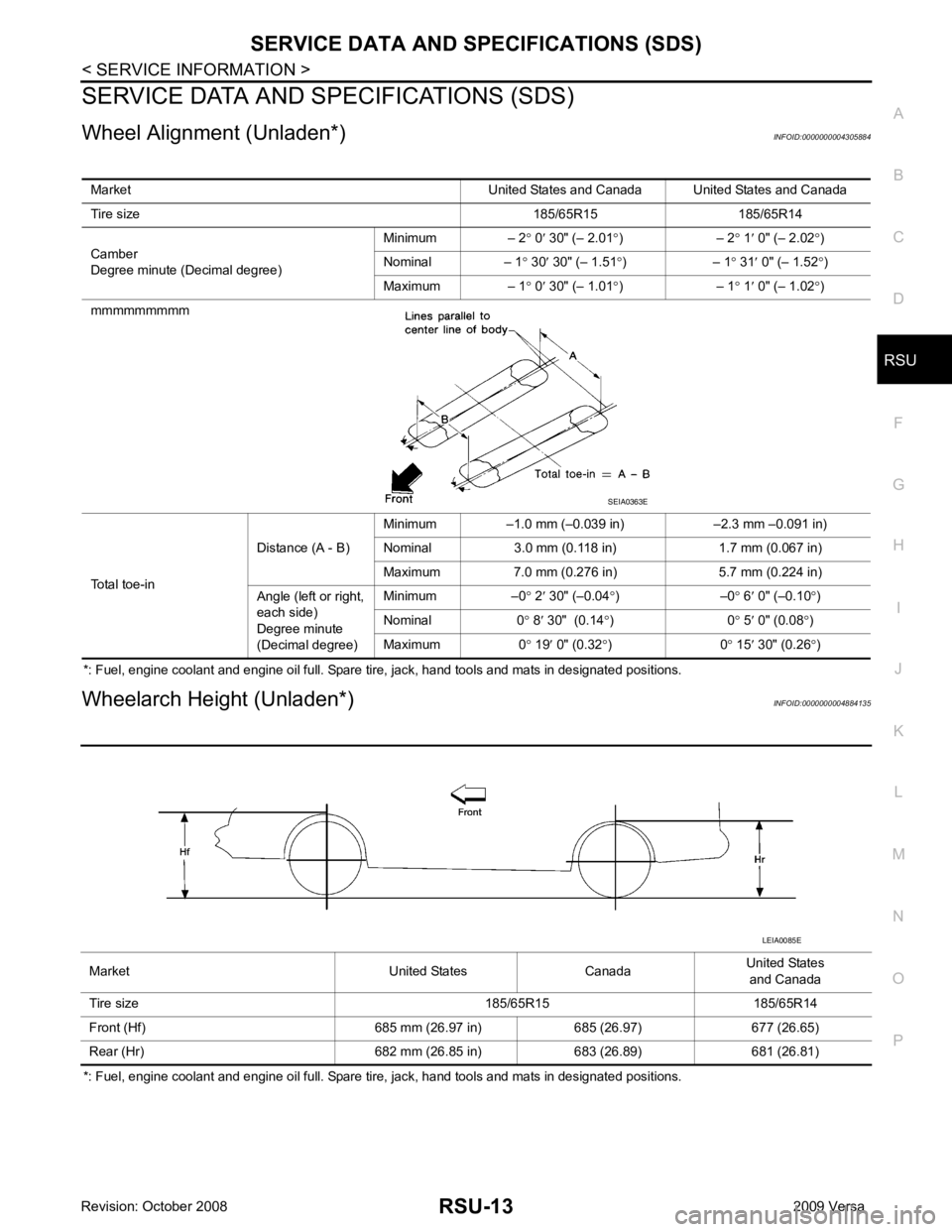
Wheelarch Height (Unladen*)
INFOID:0000000004305873
*: Fuel, engine coolant and engine oil full. Spare tire, jack, hand tools and mats in designated positions. Market United States Canada
United States
and Canada
Tire size 185/65R15 185/65R14
Front (Hf) 685 mm (26.97 in) 685 (26.97) 677 (26.65)
Rear (Hr) 682 mm (26.85 in) 683 (26.89) 681 (26.81)
Page 4124 of 4331

RSU
N
O P
SERVICE DATA AND SPECIFICATIONS (SDS)
Wheel Alignment (Unladen*) INFOID:0000000004305884
*: Fuel, engine coolant and engine oil full. Spare tire, jack, hand tools and mats in designated positions.
Wheelarch Height (Unladen*) INFOID:0000000004884135
*: Fuel, engine coolant and engine oil full. Spare tire, jack, hand tools and mats in designated positions. Market United States and Canada United States and Canada
Tire size 185/65R15 185/65R14
Camber
Degree minute (Decimal degree) Minimum – 2
° 0 ′ 30" (– 2.01 °) – 2 ° 1 ′ 0" (– 2.02 °)
Nominal – 1 ° 30 ′ 30" (– 1.51 °) – 1 ° 31 ′ 0" (– 1.52 °)
Maximum – 1 ° 0 ′ 30" (– 1.01 °) – 1 ° 1 ′ 0" (– 1.02 °)
mmmmmmmmm
Total toe-in Distance (A - B)
Minimum –1.0 mm (–0.039 in) –2.3 mm –0.091 in)
Nominal 3.0 mm (0.118 in) 1.7 mm (0.067 in)
Maximum 7.0 mm (0.276 in) 5.7 mm (0.224 in)
Angle (left or right,
each side)
Degree minute
(Decimal degree) Minimum –0
° 2 ′ 30" (–0.04 °) –0 ° 6 ′ 0" (–0.10 °)
Nominal 0 ° 8 ′ 30" (0.14 °) 0 ° 5 ′ 0" (0.08 °)
Maximum 0 ° 19 ′ 0" (0.32 °) 0 ° 15 ′ 30" (0.26 °)
Page 4243 of 4331
![NISSAN LATIO 2009 Service Repair Manual PRECAUTIONS
STC-3
< SERVICE INFORMATION >
[EPS] C
D E
F
H I
J
K L
M A
B STC
N
O
P
5. When the repair work is completed, return the ignition switch to the
″LOCK ″ position before con NISSAN LATIO 2009 Service Repair Manual PRECAUTIONS
STC-3
< SERVICE INFORMATION >
[EPS] C
D E
F
H I
J
K L
M A
B STC
N
O
P
5. When the repair work is completed, return the ignition switch to the
″LOCK ″ position before con](/manual-img/5/57359/w960_57359-4242.png)
PRECAUTIONS
STC-3
< SERVICE INFORMATION >
[EPS] C
D E
F
H I
J
K L
M A
B STC
N
O
P
5. When the repair work is completed, return the ignition switch to the
″LOCK ″ position before connecting
the battery cables. (At this time, the steering lock mechanism will engage.)
6. Perform a self-diagnosis check of al l control units using CONSULT-III.
Service Notice or Precaution for EPS System INFOID:0000000004307286
CAUTION:
Check or confirm the following item wh en performing the trouble diagnosis.
• Check any possible causes by interviewing the symptom and it’s condition from the customer if any
malfunction, such as EPS warn ing lamp turns ON, occurs.
• Check if air pressure and size of tires are proper, the specified part is used for the steering wheel,
and control unit is genuine part.
• Check if the connection of steer ing column assembly and steering gear assembly is proper (there is
not looseness of mounting bolts, damage of rods, boots or sealants, and leakage of grease, etc).
• Check if the wheel alignmen t is adjusted properly.
• Check if there is any damage or modification to su spension or body resulting in increased weight or
altered ground clearance.
• Check if installation conditions of each link and suspension are proper.
• Check if the battery voltage is proper
• Check connection conditions of each connector are proper.
• Before connecting or disconnect ing the EPS control unit har-
ness connector, turn ignition switch “OFF” and disconnect
battery ground cable. Because battery voltage is applied to
EPS control unit even if igniti on switch is turned “OFF”.
• When connecting or disconnect ing pin connectors into or
from EPS control unit, take care not to damage pin terminals
(bend or break).
When connecting pin connectors, make sure that there are no
bends or breaks on EPS control unit pin terminal.
• Before replacing EPS control unit, perform EPS control unit input/output signal inspectio n and make sure whether EPS
control unit functions properly or not. Refer to STC-9, " EPS
Control Unit Input/Output Signal Reference Value " . SEF289H
SEF291H
SDIA1848E