2009 NISSAN LATIO cruise control
[x] Cancel search: cruise controlPage 4 of 4331
ACS
N
O P
CONTENTS
AUTO CRUISE CONTROL SYSTEM
SERVICE INFORMATION .. ..........................2
AUTOMATIC SPEED CONTROL DEVICE
(ASCD) ........................................................... .....2 Precaution for Supplemental Restraint System
(SRS) "AIR BAG" and "SEAT BELT PRE-TEN-
SIONER" ............................................................. .....
2
Description ........................................................... .....2
Page 6 of 4331

AT
N
O P
CONTENTS
AUTOMATIC TRANSAXLE
SERVICE INFORMATION .. ..........................5
INDEX FOR DTC ............................................ .....5
Alphabetical Index ............................................... ......5
DTC No. Index .................................................... ......5
PRECAUTIONS .............................................. .....7
Precaution for Supplemental Restraint System
(SRS) "AIR BAG" and "SEAT BELT PRE-TEN-
SIONER" ............................................................. ......
7
Precaution Necessary fo r Steering Wheel Rota-
tion After Battery Disconnect ............................... ......
7
Precaution for On Board Diagnosis (OBD) System
of A/T and Engine ............................................... ......
8
Precaution ........................................................... ......8
Service Notice or Precaution ............................... ......9
PREPARATION .............................................. ....11
Special Service Tool ........................................... ....11
Commercial Service Tool .................................... ....14
A/T FLUID ....................................................... ....17
Checking A/T Fluid .............................................. ....17
Changing A/T Fluid ............................................. ....17
A/T Fluid Cooler Cleaning ................................... ....18
A/T CONTROL SYSTEM ................................ ....21
Cross-Sectional View ... ...........................................21
Shift Mechanism .................................................. ....22
TCM Function ...................................................... ....30
CAN Communication ........................................... ....31
Input/Output Signal of TCM ................................. ....31
Line Pressure Control .. ...........................................32
Shift Control ........................................................ ....33
Lock-up Control ................................................... ....34
Engine Brake Control (Ove rrun Clutch Control) ......35
Control Valve ....................................................... ....37
Centrifugal Cancel Mechanism ........................... ....37
ON BOARD DIAGNOSTIC (OBD) SYSTEM .. ....39
Introduction ......................................................... ....39
OBD-II Function for A/T System .......................... ....39 One or Two Trip Detection Logic of OBD-II .........
....39
OBD-II Diagnostic Trouble Code (DTC) .............. ....39
Malfunction Indicator Lamp (MIL) ............................41
TROUBLE DIAGNOSIS .................................... 42
DTC Inspection Priority Chart .............................. ....42
Fail-Safe .............................................................. ....42
How to Perform Trouble Diagnosis for Quick and
Accurate Repair ................................................... ....
43
A/T Electrical Parts Location ............................... ....49
Circuit Diagram .................................................... ....50
Inspections Before Trouble Diagnosis ................. ....51
Road Test ............................................................ ....55
Check Before Engine Is Started .......................... ....56
Check at Idle ........................................................ ....56
Cruise Test - Part 1 ............................................. ....58
Cruise Test - Part 2 ............................................. ....61
Cruise Test - Part 3 ............................................. ....62
Vehicle Speed at Which Gear Shifting Occurs .... ....64
Vehicle Speed at Which Lock-up Occurs/Releas-
es ......................................................................... ....
64
Symptom Chart .................................................... ....65
TCM Terminal and Refere nce Value .......................77
CONSULT-III Function (TRANSMISSION) .......... ....79
Diagnosis Procedure withou t CONSULT-III ............83
DTC U1000 CAN COMMUNICATION LINE ..... 88
Description ........................................................... ....88
On Board Diagnosis Logic ................................... ....88
Possible Cause .................................................... ....88
DTC Confirmation Procedure .............................. ....88
Wiring Diagram - AT - CAN ................................. ....89
Diagnosis Procedure ........................................... ....90
DTC P0705 PARK/NEUTRAL POSITION
(PNP) SWITCH .................................................. 91
Description ........................................................... ....91
CONSULT-III Reference Va lue in Data Monitor
Mode .................................................................... ....
91
On Board Diagnosis Logic ................................... ....91
Possible Cause .................................................... ....91
Page 60 of 4331
AT
N
O P
Line Pressure
Judgement of Line Pressure Test
Road Test INFOID:0000000004305320
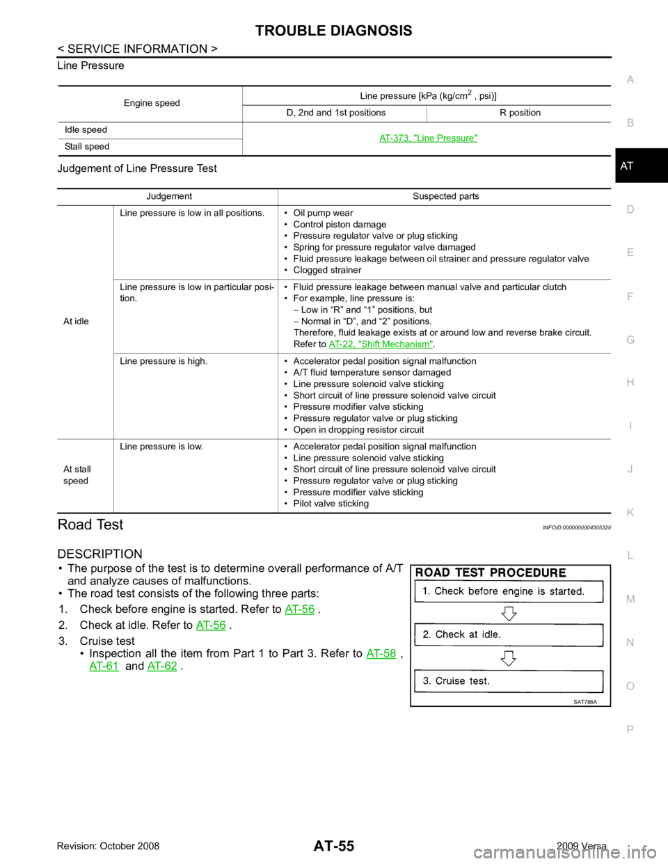
DESCRIPTION • The purpose of the test is to det ermine overall performance of A/T
and analyze causes of malfunctions.
• The road test consists of the following three parts:
1. Check before engine is started. Refer to AT-56 .
2. Check at idle. Refer to AT-56 .
3. Cruise test • Inspection all the item from Part 1 to Part 3. Refer to AT-58 ,
AT-61 and
AT-62 .
Engine speed
Line pressure [kPa (kg/cm
2
, psi)]
D, 2nd and 1st positions R position
Idle speed AT-373, " Line Pressure "
Stall speed
Judgement Suspected parts
At idle Line pressure is low in all positions. • Oil pump wear
• Control piston damage
• Pressure regulator valve or plug sticking
• Spring for pressure regulator valve damaged
• Fluid pressure leakage between oil strainer and pressure regulator valve
• Clogged strainer
Line pressure is low in particular posi-
tion. • Fluid pressure leakage between manual valve and particular clutch
• For example, line pressure is: − Low in “R” and “1 ” positions, but
− Normal in “D”, and “2” positions.
Therefore, fluid leakage exists at or around low and reverse brake circuit.
Refer to AT-22, " Shift Mechanism " .
Line pressure is high. • Accelerator pedal position signal malfunction • A/T fluid temperature sensor damaged
• Line pressure solenoid valve sticking
• Short circuit of line pressure solenoid valve circuit
• Pressure modifier valve sticking
• Pressure regulator valve or plug sticking
• Open in dropping resistor circuit
At stall
speed Line pressure is low. • Accelerator pedal position signal malfunction
• Line pressure solenoid valve sticking
• Short circuit of line pressure solenoid valve circuit
• Pressure regulator valve or plug sticking
• Pressure modifier valve sticking
• Pilot valve sticking
Page 66 of 4331

TROUBLE DIAGNOSIS
AT-61
< SERVICE INFORMATION >
D
E
F
G H
I
J
K L
M A
B AT
N
O P
• Continue “Road Test”. 8.
CHECK SHIFT-DOWN (D 4 TO D 3 )
Decelerate vehicle by applying foot brake lightly. Read gear position and engine speed. Refer to AT-79, " CON-
SULT-III Functi
on (TRANSMISSION) " .
Does engine speed return to idle smoothly when A/T is shifted from D 4 to D 3 ?
YES >> 1. Stop vehicle.
2. Go to AT-61, " Cruise Test - Part 2 " .
NO >> • Mark the box on the “D iagnostic Worksheet Chart”.
• Go to AT-197, " Engine Speed Does Not Return to Idle
(Light Braking D 4 → D 3 ) " .
• Continue “Road Test”.
Cruise Test - Part 2 INFOID:00000000043053241.
CHECK STARTING GEAR (D 1 ) POSITION
1. Push overdrive control switch. (OD OFF indicator lamp is off.)
2. Move selector lever to “D” position.
3. Accelerate vehicle by half throttle again.
Read gear position. Refer to AT-79, " CONSULT-III Func-
tion (TRANSMISSION) " .
Does vehicle start from D 1 ?
YES >> GO TO 2.
NO >> • Mark the box on the “D iagnostic Worksheet Chart”.
• Go to AT-188, " Vehicle Cannot Be Started from D 1 " .
• Continue “Road Test”. 2.
CHECK SHIFT-UP AND SHIFT-DOWN (D 3 TO D 4 TO D 2 )
1. Accelerate vehicle to 80 km/h (50 MPH) as shown in the figure.
2. Release accelerator pedal and then quickly depress it fully.
Read gear position and th rottle opening. Refer to AT-79," CONSULT-III Function (TRANSMISSION) " .
Does A/T shift from D 4 to D 2 as soon as accelerator pedal is
depressed fully?
YES >> GO TO 3.
NO >> • Mark the box on the “D iagnostic Worksheet Chart”.
• Go to AT-190, " A/T Does Not Shift: D 1 → D 2 or Does
Not Kickdown: D 4 → D 2 " .
• Continue “Road Test”. 3.
CHECK SHIFT-UP (D 2 TO D 3 )
Check shift-up (D 2 to D 3 )
Specified speed when shifting from D 2 to D 3 . Refer to AT-64, " Vehicle Speed at Which Gear Shifting Occurs " .SAT959I
SAT495G
SCIA7192E
Page 127 of 4331
AT-122< SERVICE INFORMATION >
DTC P0734 A/T 4TH GEAR FUNCTION
- Valve, sleeve and plug slide along valve bore under their own weight.
- Valve, sleeve and plug are free from burrs, dents and scratches.
- Control valve springs are free from damage, deformation and fatigue.
- Hydraulic line is free from obstacles.
OK or NG OK >> GO TO 6.
NG >> Repair control valve. 6.
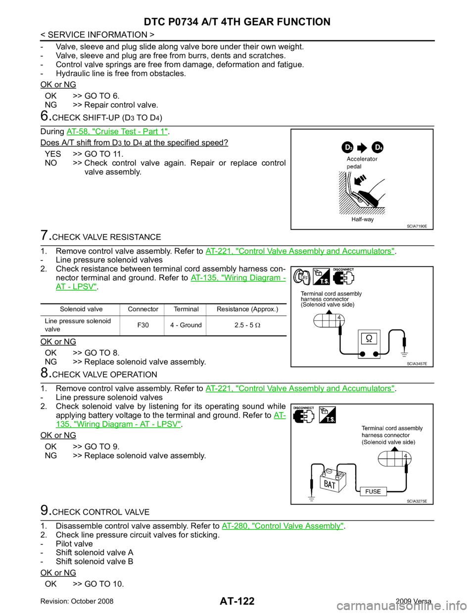
CHECK SHIFT-UP (D 3 TO D 4)
During AT-58, " Cruise Test - Part 1 " .
Does A/T shift from D 3 to D 4 at the specified speed?
YES >> GO TO 11.
NO >> Check control valve again. Repair or replace control
valve assembly. 7.
CHECK VALVE RESISTANCE
1. Remove control valve assembly. Refer to AT-221, " Control Valve Assembly and Accumulators " .
- Line pressure solenoid valves
2. Check resistance between terminal cord assembly harness con- nector terminal and ground. Refer to AT-135, " Wiring Diagram -
AT - LPSV " .
OK or NG OK >> GO TO 8.
NG >> Replace solenoid valve assembly. 8.
CHECK VALVE OPERATION
1. Remove control valve assembly. Refer to AT-221, " Control Valve Assembly and Accumulators " .
- Line pressure solenoid valves
2. Check solenoid valve by listening for its operating sound while
applying battery voltage to the terminal and ground. Refer to AT-135, " Wiring Diagram - AT - LPSV " .
OK or NG OK >> GO TO 9.
NG >> Replace solenoid valve assembly. 9.
CHECK CONTROL VALVE
1. Disassemble control valve assembly. Refer to AT-280, " Control Valve Assembly " .
2. Check line pressure circuit valves for sticking.
- Pilot valve
- Shift solenoid valve A
- Shift solenoid valve B
OK or NG OK >> GO TO 10. SCIA7190E
Solenoid valve Connector Terminal Resistance (Approx.)
Line pressure solenoid
valve F30 4 - Ground 2.5 - 5
Ω SCIA3457E
SCIA3275E
Page 128 of 4331
DTC P0734 A/T 4TH GEAR FUNCTION
AT-123
< SERVICE INFORMATION >
D
E
F
G H
I
J
K L
M A
B AT
N
O P
NG >> Repair control valve. 10.
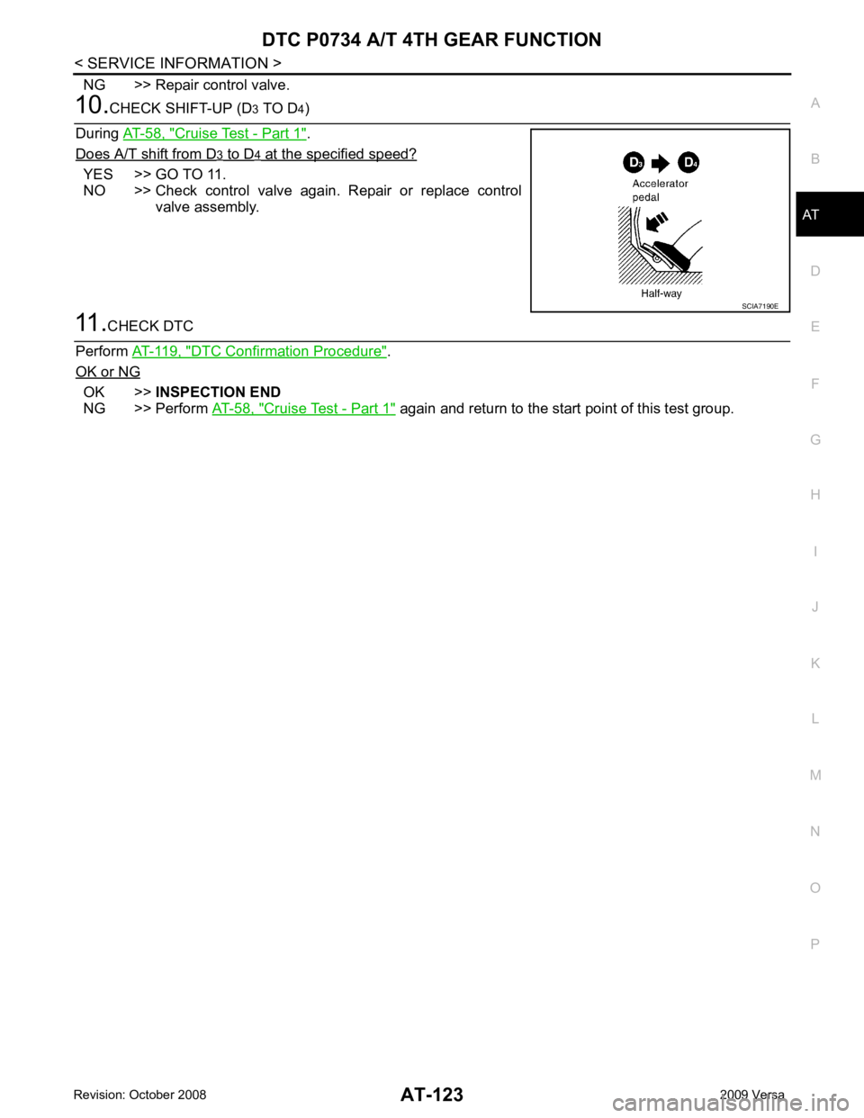
CHECK SHIFT-UP (D 3 TO D 4)
During AT-58, " Cruise Test - Part 1 " .
Does A/T shift from D 3 to D 4 at the specified speed?
YES >> GO TO 11.
NO >> Check control valve again. Repair or replace control
valve assembly. 11.
CHECK DTC
Perform AT-119, " DTC Confirmation Procedure " .
OK or NG OK >>
INSPECTION END
NG >> Perform AT-58, " Cruise Test - Part 1 " again and return to the start point of this test group. SCIA7190E
Page 135 of 4331
AT-130< SERVICE INFORMATION >
DTC P0744 A/T TCC S/V FUNCTION (LOCK-UP)
5. Accelerate vehicle to more than 80 km/h (50 MPH) and maintain the following conditions continuously until “TESTING” has turned to “COMPLETE”. (It wi ll take approximately 30 seconds after “TESTING”
shows.)
THROTTLE POSI: 1.0/8 - 2.0/8 (at all times during step 4)
SLCT LVR POSI: “D” position
TCC S/V DUTY: More than 94%
VEHICLE SPEED: Constant speed of more than 80 km/h (50 MPH)
- Make sure that “GEAR” shows “4”.
- For shift schedule, refer to AT-64, " Vehicle Speed at Which Gear Shifting Occurs " .
- If “TESTING” does not ap pear on CONSULT-III for a long ti me, select “SELF-DIAG RESULTS”. In
case a DTC other than “P0744 A/T TCC S/ V FNCTN” is shown, refer to AT-79, " CONSULT-III Func-
tion (TRANSMISSION) " .
6. Make sure that “OK” is displayed. (If “NG” is displayed, refer to “DIAGNOSTIC PROCEDURE”.)
Refer to AT-130, " Diagnosis Procedure " .
Refer to AT-64, " Vehicle Speed at Which Lock-up Occurs/Releases " .
WITH GST
Follow the procedure “WITH CONSULT-III”.
Diagnosis Procedure INFOID:00000000043054021.
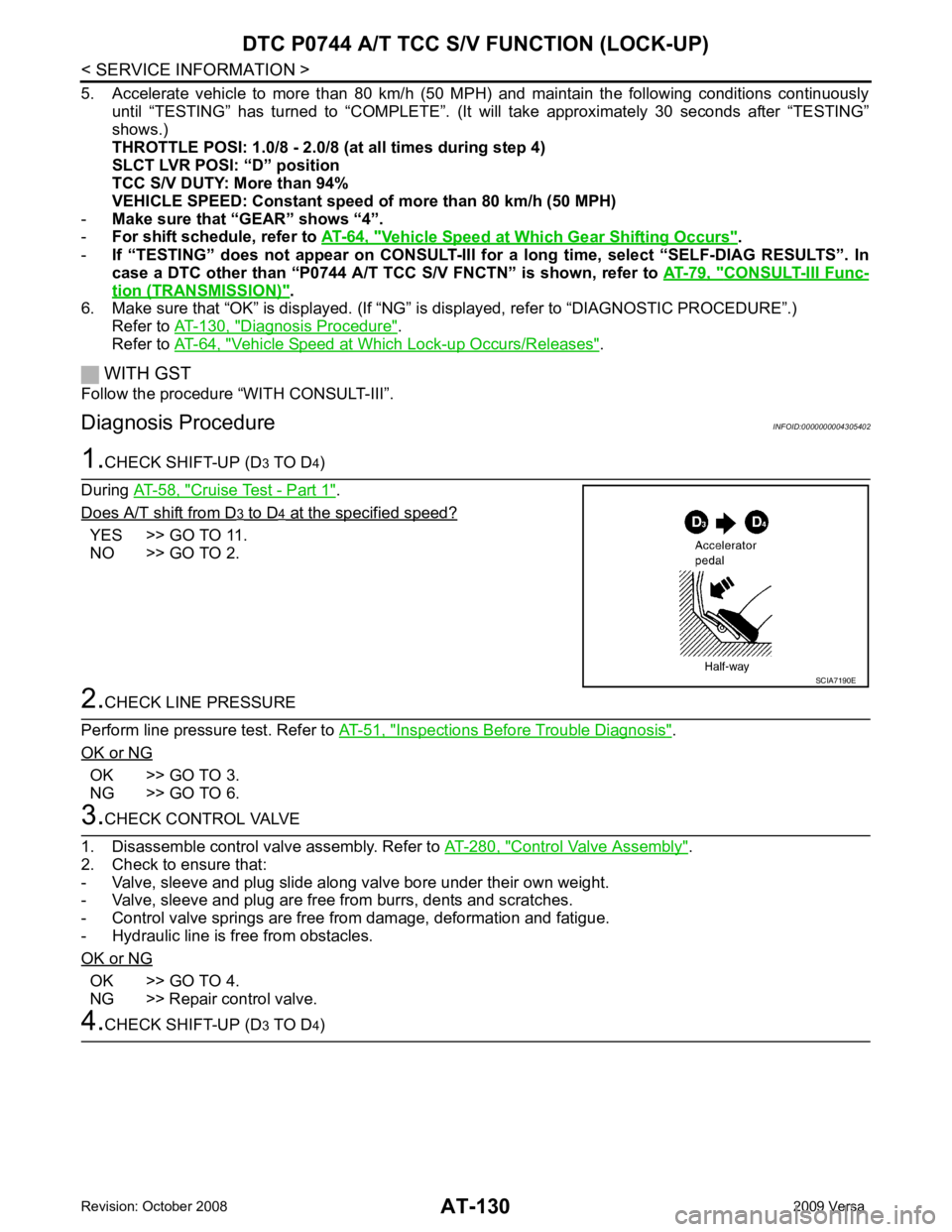
CHECK SHIFT-UP (D 3 TO D 4)
During AT-58, " Cruise Test - Part 1 " .
Does A/T shift from D 3 to D 4 at the specified speed?
YES >> GO TO 11.
NO >> GO TO 2. 2.
CHECK LINE PRESSURE
Perform line pressure test. Refer to AT-51, " Inspections Before Trouble Diagnosis " .
OK or NG OK >> GO TO 3.
NG >> GO TO 6. 3.
CHECK CONTROL VALVE
1. Disassemble control valve assembly. Refer to AT-280, " Control Valve Assembly " .
2. Check to ensure that:
- Valve, sleeve and plug slide along valve bore under their own weight.
- Valve, sleeve and plug are free from burrs, dents and scratches.
- Control valve springs are free from damage, deformation and fatigue.
- Hydraulic line is free from obstacles.
OK or NG OK >> GO TO 4.
NG >> Repair control valve. 4.
CHECK SHIFT-UP (D 3 TO D 4) SCIA7190E
Page 136 of 4331
DTC P0744 A/T TCC S/
V FUNCTION (LOCK-UP)
AT-131
< SERVICE INFORMATION >
D
E
F
G H
I
J
K L
M A
B AT
N
O P
During
AT-58, " Cruise Test - Part 1 " .
Does A/T shift from D 3 to D 4 at the specified speed?
YES >> GO TO 5.
NO >> Check control valve again. Repair or replace control valve assembly. 5.
CHECK DTC
Perform AT-129, " DTC Confirmation Procedure " .
OK or NG OK >>
INSPECTION END
NG >> GO TO 11. Check for proper lock-up. 6.
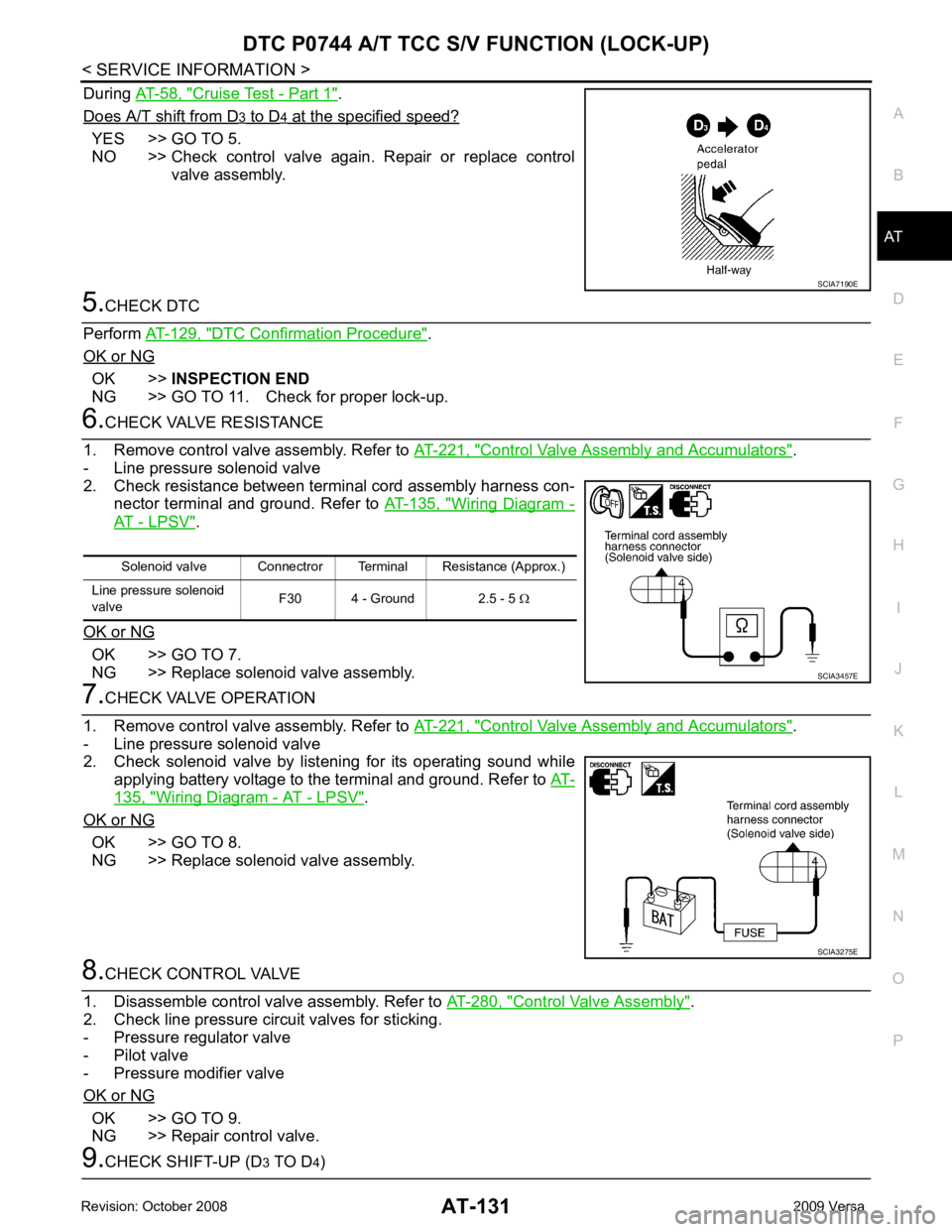
CHECK VALVE RESISTANCE
1. Remove control valve assembly. Refer to AT-221, " Control Valve Assembly and Accumulators " .
- Line pressure solenoid valve
2. Check resistance between terminal cord assembly harness con- nector terminal and ground. Refer to AT-135, " Wiring Diagram -
AT - LPSV " .
OK or NG OK >> GO TO 7.
NG >> Replace solenoid valve assembly. 7.
CHECK VALVE OPERATION
1. Remove control valve assembly. Refer to AT-221, " Control Valve Assembly and Accumulators " .
- Line pressure solenoid valve
2. Check solenoid valve by listening for its operating sound while
applying battery voltage to the terminal and ground. Refer to AT-135, " Wiring Diagram - AT - LPSV " .
OK or NG OK >> GO TO 8.
NG >> Replace solenoid valve assembly. 8.
CHECK CONTROL VALVE
1. Disassemble control valve assembly. Refer to AT-280, " Control Valve Assembly " .
2. Check line pressure circuit valves for sticking.
- Pressure regulator valve
- Pilot valve
- Pressure modifier valve
OK or NG OK >> GO TO 9.
NG >> Repair control valve. 9.
CHECK SHIFT-UP (D 3 TO D 4) SCIA7190E
Solenoid valve Connectror Terminal Resistance (Approx.)
Line pressure solenoid
valve F30 4 - Ground 2.5 - 5
Ω SCIA3457E
SCIA3275E