2009 NISSAN LATIO automatic transmission
[x] Cancel search: automatic transmissionPage 6 of 4331

AT
N
O P
CONTENTS
AUTOMATIC TRANSAXLE
SERVICE INFORMATION .. ..........................5
INDEX FOR DTC ............................................ .....5
Alphabetical Index ............................................... ......5
DTC No. Index .................................................... ......5
PRECAUTIONS .............................................. .....7
Precaution for Supplemental Restraint System
(SRS) "AIR BAG" and "SEAT BELT PRE-TEN-
SIONER" ............................................................. ......
7
Precaution Necessary fo r Steering Wheel Rota-
tion After Battery Disconnect ............................... ......
7
Precaution for On Board Diagnosis (OBD) System
of A/T and Engine ............................................... ......
8
Precaution ........................................................... ......8
Service Notice or Precaution ............................... ......9
PREPARATION .............................................. ....11
Special Service Tool ........................................... ....11
Commercial Service Tool .................................... ....14
A/T FLUID ....................................................... ....17
Checking A/T Fluid .............................................. ....17
Changing A/T Fluid ............................................. ....17
A/T Fluid Cooler Cleaning ................................... ....18
A/T CONTROL SYSTEM ................................ ....21
Cross-Sectional View ... ...........................................21
Shift Mechanism .................................................. ....22
TCM Function ...................................................... ....30
CAN Communication ........................................... ....31
Input/Output Signal of TCM ................................. ....31
Line Pressure Control .. ...........................................32
Shift Control ........................................................ ....33
Lock-up Control ................................................... ....34
Engine Brake Control (Ove rrun Clutch Control) ......35
Control Valve ....................................................... ....37
Centrifugal Cancel Mechanism ........................... ....37
ON BOARD DIAGNOSTIC (OBD) SYSTEM .. ....39
Introduction ......................................................... ....39
OBD-II Function for A/T System .......................... ....39 One or Two Trip Detection Logic of OBD-II .........
....39
OBD-II Diagnostic Trouble Code (DTC) .............. ....39
Malfunction Indicator Lamp (MIL) ............................41
TROUBLE DIAGNOSIS .................................... 42
DTC Inspection Priority Chart .............................. ....42
Fail-Safe .............................................................. ....42
How to Perform Trouble Diagnosis for Quick and
Accurate Repair ................................................... ....
43
A/T Electrical Parts Location ............................... ....49
Circuit Diagram .................................................... ....50
Inspections Before Trouble Diagnosis ................. ....51
Road Test ............................................................ ....55
Check Before Engine Is Started .......................... ....56
Check at Idle ........................................................ ....56
Cruise Test - Part 1 ............................................. ....58
Cruise Test - Part 2 ............................................. ....61
Cruise Test - Part 3 ............................................. ....62
Vehicle Speed at Which Gear Shifting Occurs .... ....64
Vehicle Speed at Which Lock-up Occurs/Releas-
es ......................................................................... ....
64
Symptom Chart .................................................... ....65
TCM Terminal and Refere nce Value .......................77
CONSULT-III Function (TRANSMISSION) .......... ....79
Diagnosis Procedure withou t CONSULT-III ............83
DTC U1000 CAN COMMUNICATION LINE ..... 88
Description ........................................................... ....88
On Board Diagnosis Logic ................................... ....88
Possible Cause .................................................... ....88
DTC Confirmation Procedure .............................. ....88
Wiring Diagram - AT - CAN ................................. ....89
Diagnosis Procedure ........................................... ....90
DTC P0705 PARK/NEUTRAL POSITION
(PNP) SWITCH .................................................. 91
Description ........................................................... ....91
CONSULT-III Reference Va lue in Data Monitor
Mode .................................................................... ....
91
On Board Diagnosis Logic ................................... ....91
Possible Cause .................................................... ....91
Page 44 of 4331
AT
N
O P
ON BOARD DIAGNOSTIC (OBD) SYSTEM
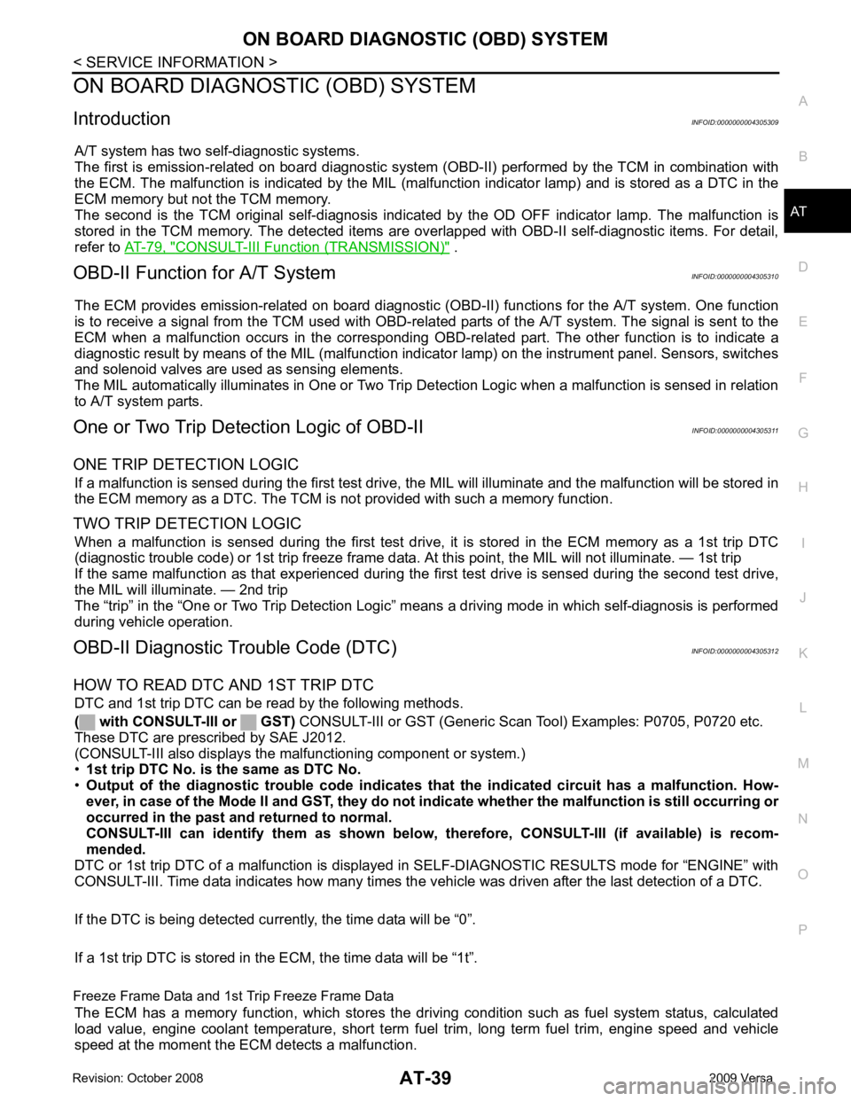
Introduction INFOID:0000000004305309
A/T system has two self-diagnostic systems.
The first is emission-related on boar d diagnostic system (OBD-II) performed by the TCM in combination with
the ECM. The malfunction is indicated by the MIL (malf unction indicator lamp) and is stored as a DTC in the
ECM memory but not the TCM memory.
The second is the TCM original self-diagnosis indicated by the OD OFF indicator lamp. The malfunction is
stored in the TCM memory. The detected items are ov erlapped with OBD-II self-diagnostic items. For detail,
refer to AT-79, " CONSULT-III Function (TRANSMISSION) " .
OBD-II Function for A/T System INFOID:0000000004305310
The ECM provides emission-related on board diagnostic (O BD-II) functions for the A/T system. One function
is to receive a signal from the TCM used with OBD-rela ted parts of the A/T system. The signal is sent to the
ECM when a malfunction occurs in the corresponding OBD-re lated part. The other function is to indicate a
diagnostic result by means of the MIL (malfunction indica tor lamp) on the instrument panel. Sensors, switches
and solenoid valves are used as sensing elements.
The MIL automatically illuminates in One or Two Trip Detection Logic when a malfunction is sensed in relation
to A/T system parts.
One or Two Trip Detection Logic of OBD-II INFOID:0000000004305311
ONE TRIP DETECTION LOGIC If a malfunction is sensed during the first test drive, the MIL will illuminate and the malfunction will be stored in
the ECM memory as a DTC. The TCM is not provided with such a memory function.
TWO TRIP DETECTION LOGIC When a malfunction is sensed during the first test drive, it is stored in the ECM memory as a 1st trip DTC
(diagnostic trouble code) or 1st trip freeze frame data. At this point, the MIL will not illuminate. — 1st trip
If the same malfunction as that experienced during the fi rst test drive is sensed during the second test drive,
the MIL will illuminate. — 2nd trip
The “trip” in the “One or Two Trip Detection Logic” m eans a driving mode in which self-diagnosis is performed
during vehicle operation.
OBD-II Diagnostic Trouble Code (DTC) INFOID:0000000004305312
HOW TO READ DTC AND 1ST TRIP DTC DTC and 1st trip DTC can be read by the following methods.
( with CONSULT-III or GST) CONSULT-III or GST (Generic Scan Tool) Examples: P0705, P0720 etc.
These DTC are prescribed by SAE J2012.
(CONSULT-III also displays the malfunctioning component or system.)
• 1st trip DTC No. is the same as DTC No.
• Output of the diagnostic troubl e code indicates that the indicated circuit has a malfunction. How-
ever, in case of the Mode II and GST, they do not indicate whether the malfunction is still occurring or
occurred in the past and returned to normal.
CONSULT-III can identify them as shown below, therefore, CONS ULT-III (if available) is recom-
mended.
DTC or 1st trip DTC of a malfunction is displayed in SELF-DIAGNOSTIC RESULTS mode for “ENGINE” with
CONSULT-III. Time data indicates how many times the vehicle was driven after the last detection of a DTC.
If the DTC is being detected curr ently, the time data will be “0”.
If a 1st trip DTC is stored in the ECM, the time data will be “1t”.
Freeze Frame Data and 1st Trip Freeze Frame Data The ECM has a memory function, which stores the driv ing condition such as fuel system status, calculated
load value, engine coolant temperature, short term f uel trim, long term fuel trim, engine speed and vehicle
speed at the moment the ECM detects a malfunction.
Page 168 of 4331
AT
N
O P
DTC TURBINE REVOLUTION SENSOR
Description INFOID:0000000004305450
The turbine revolution sensor (power train revolution s ensor) detects forward clutch drum rpm (revolutions per
minute). It is located on the input side of the automat ic transaxle. The vehicle speed sensor A/T (Revolution
sensor) is located on the output side of the automatic transaxle. With the two sensors, input and output rpms
are accurately detected. As a resu lt, optimal shift timing during deceleration and shift quality can be improved.
CONSULT-III Reference Val ue in Data Monitor Mode INFOID:0000000004305451
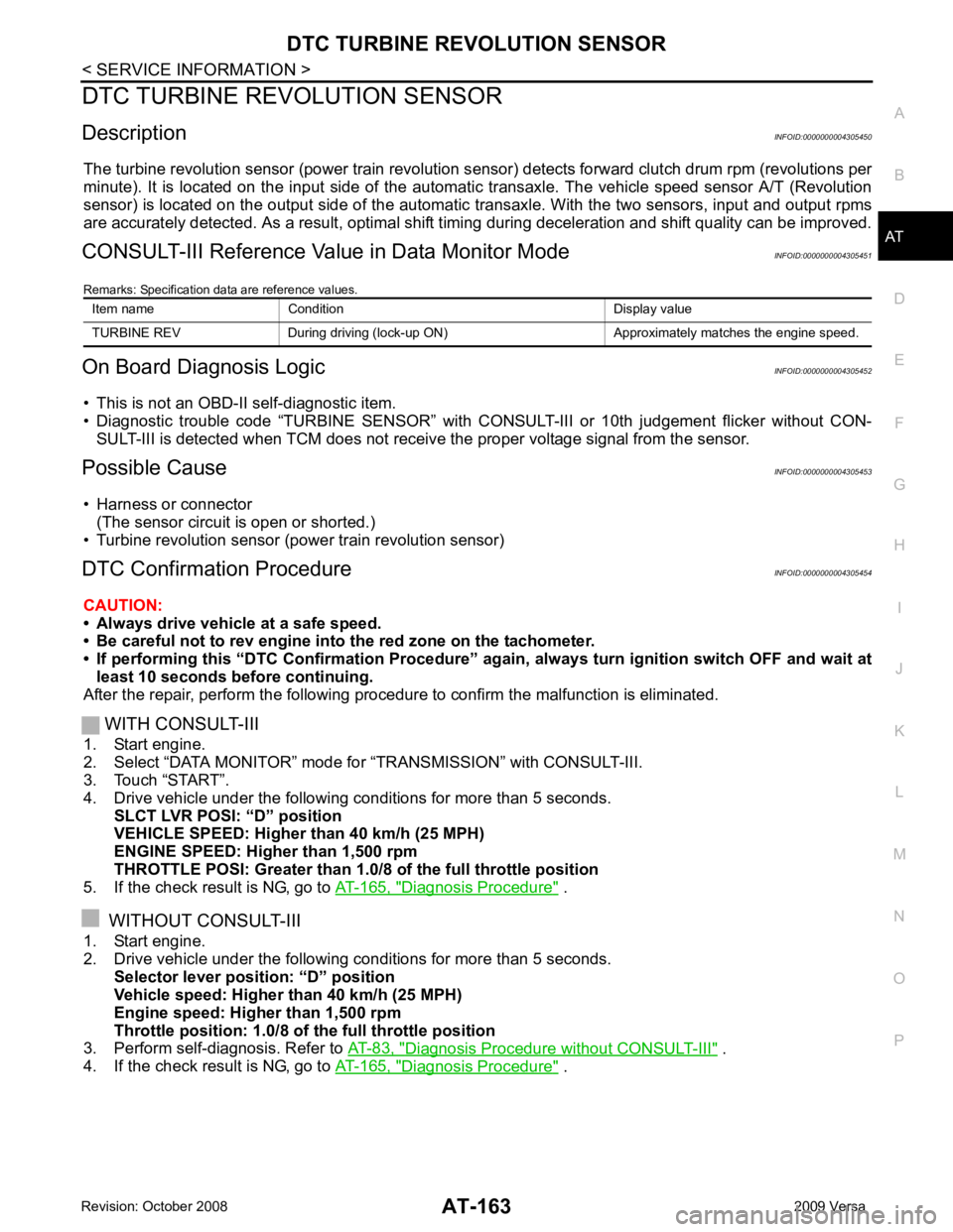
Remarks: Specification data are reference values.
On Board Diagnosis Logic INFOID:0000000004305452
• This is not an OBD-II self-diagnostic item.
• Diagnostic trouble code “TURBINE SENSOR” with CO NSULT-III or 10th judgement flicker without CON-
SULT-III is detected when TCM does not receiv e the proper voltage signal from the sensor.
Possible Cause INFOID:0000000004305453
• Harness or connector (The sensor circuit is open or shorted.)
• Turbine revolution sensor (power train revolution sensor)
DTC Confirmation Procedure INFOID:0000000004305454
CAUTION:
• Always drive vehicle at a safe speed.
• Be careful not to rev engine into the red zone on the tachometer.
• If performing this “DTC Confirmation Procedure” again, always turn ignition switch OFF and wait at
least 10 seconds before continuing.
After the repair, perform the following procedure to confirm the malfunction is eliminated.
WITH CONSULT-III
1. Start engine.
2. Select “DATA MONITOR” mode for “TRANSMISSION” with CONSULT-III.
3. Touch “START”.
4. Drive vehicle under the following conditions for more than 5 seconds. SLCT LVR POSI: “D” position
VEHICLE SPEED: Higher than 40 km/h (25 MPH)
ENGINE SPEED: Higher than 1,500 rpm
THROTTLE POSI: Greater than 1.0/ 8 of the full throttle position
5. If the check result is NG, go to AT-165, " Diagnosis Procedure " .
WITHOUT CONSULT-III
1. Start engine.
2. Drive vehicle under the following conditions for more than 5 seconds. Selector lever posi tion: “D” position
Vehicle speed: Higher than 40 km/h (25 MPH)
Engine speed: Higher than 1,500 rpm
Throttle position: 1.0/8 of the full throttle position
3. Perform self-diagnosis. Refer to AT-83, " Diagnosis Procedure without CONSULT-III " .
4. If the check result is NG, go to AT-165, " Diagnosis Procedure " .
Item name Condition Display value
TURBINE REV During driving (lock-up ON) Approximately matches the engine speed.
Page 377 of 4331
.
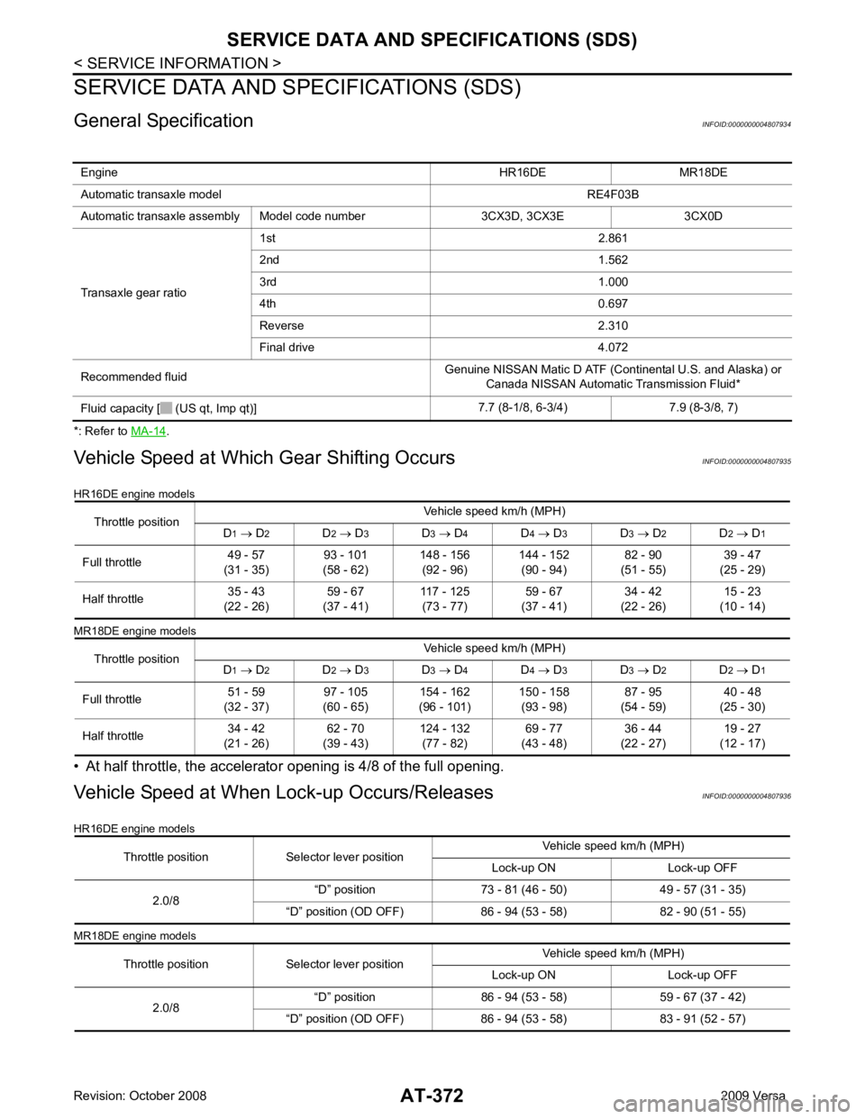
Vehicle Speed at Which Gear Shifting Occurs INFOID:0000000004807935
HR16DE engine models
MR18DE engine models
• At half throttle, the accelerator opening is 4/8 of the full opening.
Vehicle Speed at When Lock-up Occurs/Releases INFOID:0000000004807936
HR16DE engine models
MR18DE engine models Engine
HR16DE MR18DE
Automatic transaxle model RE4F03B
Automatic transaxle assembly Model code number 3CX3D, 3CX3E 3CX0D
Transaxle gear ratio 1st 2.861
2nd 1.562
3rd 1.000
4th 0.697
Reverse 2.310
Final drive 4.072
Recommended fluid Genuine NISSAN Matic D ATF (Conti
nental U.S. and Alaska) or
Canada NISSAN Automatic Transmission Fluid*
Fluid capacity [ (US qt, Imp qt)] 7.7 (8-1/8, 6-3/4) 7.9 (8-3/8, 7)Throttle position
Vehicle speed km/h (MPH)
D 1
→ D 2 D2 → D 3 D3 → D 4 D4 → D 3 D3 → D 2 D2 → D 1
Full throttle 49 - 57
(31 - 35) 93 - 101
(58 - 62) 148 - 156
(92 - 96) 144 - 152
(90 - 94) 82 - 90
(51 - 55) 39 - 47
(25 - 29)
Half throttle 35 - 43
(22 - 26) 59 - 67
(37 - 41) 117 - 125
(73 - 77) 59 - 67
(37 - 41) 34 - 42
(22 - 26) 15 - 23
(10 - 14)
Throttle position Vehicle speed km/h (MPH)
D 1 → D 2 D2 → D 3 D3 → D 4 D4 → D 3 D3 → D 2 D2 → D 1
Full throttle 51 - 59
(32 - 37) 97 - 105
(60 - 65) 154 - 162
(96 - 101) 150 - 158
(93 - 98) 87 - 95
(54 - 59) 40 - 48
(25 - 30)
Half throttle 34 - 42
(21 - 26) 62 - 70
(39 - 43) 124 - 132
(77 - 82) 69 - 77
(43 - 48) 36 - 44
(22 - 27) 19 - 27
(12 - 17) Throttle position Selector lever position
Vehicle speed km/h (MPH)
Lock-up ON Lock-up OFF
2.0/8 “D” position 73 - 81 (46
- 50) 49 - 57 (31 - 35)
“D” position (OD OFF) 86 - 94 (53 - 58) 82 - 90 (51 - 55)
Throttle position Selector lever position Vehicle speed km/h (MPH)
Lock-up ON Lock-up OFF
2.0/8 “D” position 86 - 94 (53
- 58) 59 - 67 (37 - 42)
“D” position (OD OFF) 86 - 94 (53 - 58) 83 - 91 (52 - 57)
Page 571 of 4331
BL-110< SERVICE INFORMATION >
INTELLIGENT KEY SYSTEM
*1: With continuously variable transmissi on (CVT) or automatic transmission (A/T).
*2: With manual transmission (M/T).
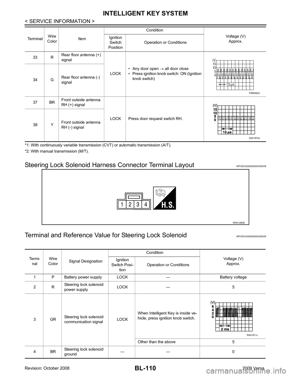
Steering Lock Solenoid Harn ess Connector Terminal Layout INFOID:0000000004305038
Terminal and Reference Valu e for Steering Lock Solenoid INFOID:0000000004305039
33 R
Rear floor antenna (+)
signal
LOCK• Any door open
→ all door close
• Press ignition knob switch: ON (Ignition knob switch)
34 G Rear floor antenna (-)
signal
37 BR Front outside antenna
RH (+) signal
LOCK Press door request switch RH.
38 Y Front outside antenna
RH (-) signal
Terminal
Wire
Color Item Condition
Voltage (V)Approx.
Ignition
Switch
Position Operation or Conditions PIIB5502J
SIIA1910J
WIIA1283E
Termi-
nal Wire
Color Signal Designation Condition
Voltage (V)Approx.
Ignition
Switch Posi- tion Operation or Conditions
1 P Battery power supply LOCK — Battery voltage
2 R Steering lock solenoid
power supply LOCK — 5
3 GR Steering lock solenoid
communication signal LOCKWhen Intelligent Key is inside ve-
hicle, press ignition knob switch.
Other than the above 5
4 BR Steering lock solenoid
ground — — 0 SIIA1911J
Page 642 of 4331
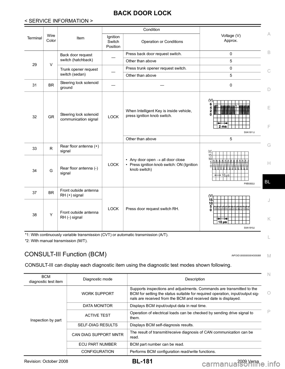
BACK DOOR LOCK
BL-181
< SERVICE INFORMATION >
C
D E
F
G H
J
K L
M A
B BL
N
O P
*1: With continuously variable transmission (CVT) or automatic transmission (A/T).
*2: With manual transmission (M/T).
CONSULT-III Function (BCM) INFOID:0000000004305088
CONSULT-III can display each diagnostic item using the diagnostic test modes shown following. 29 V
Back door request
switch (hatchback) —Press back door request switch. 0
Other than above 5
Trunk opener request
switch (sedan) —Press trunk opener request switch. 0
Other than above 5
31 BR Steering lock solenoid
ground — — 0
32 GR Steering lock solenoid
communication signal LOCKWhen Intelligent Key is inside vehicle,
press ignition knob switch.
Other than above 5
33 R Rear floor antenna (+)
signal
LOCK• Any door open
→ all door close
• Press ignition knob switch: ON (Ignition
knob switch)
34 G Rear floor antenna (-)
signal
37 BR Front outside antenna
RH (+) signal
LOCK Press door request switch RH.
38 Y Front outside antenna
RH (-) signal
Terminal
Wire
Color Item Condition
Voltage (V)Approx.
Ignition
Switch
Position Operation or Conditions SIIA1911J
PIIB5502J
SIIA1910J
BCM
diagnostic test item Diagnostic mode Description
Inspection by part WORK SUPPORT
Supports inspections and adjustments. Commands are transmitted to the
BCM for setting the status suitable for required operation, input/output sig-
nals are received from the BCM and received date is displayed.
DATA MONITOR Displays BCM input/output data in real time.
ACTIVE TEST Operation of electrical loads can be checked by sending drive signal to
them.
SELF-DIAG RESULTS Displays BC M self-diagnosis results.
CAN DIAG SUPPORT MNTR The result of transmit/receive diagnosis of CAN communication can be
read.
ECU PART NUMBER BCM part number can be read.
CONFIGURATION Performs BCM configuration read/write functions.
Page 666 of 4331
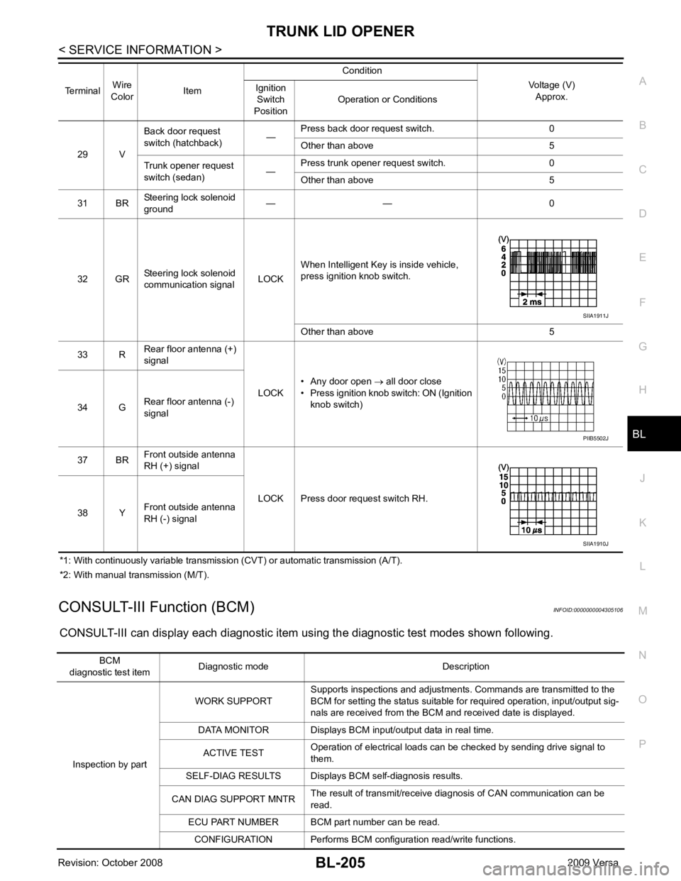
TRUNK LID OPENER
BL-205
< SERVICE INFORMATION >
C
D E
F
G H
J
K L
M A
B BL
N
O P
*1: With continuously variable transmission (CVT) or automatic transmission (A/T).
*2: With manual transmission (M/T).
CONSULT-III Function (BCM) INFOID:0000000004305106
CONSULT-III can display each diagnostic item using the diagnostic test modes shown following. 29 V
Back door request
switch (hatchback) —Press back door request switch. 0
Other than above 5
Trunk opener request
switch (sedan) —Press trunk opener request switch. 0
Other than above 5
31 BR Steering lock solenoid
ground — — 0
32 GR Steering lock solenoid
communication signal LOCKWhen Intelligent Key is inside vehicle,
press ignition knob switch.
Other than above 5
33 R Rear floor antenna (+)
signal
LOCK• Any door open
→ all door close
• Press ignition knob switch: ON (Ignition
knob switch)
34 G Rear floor antenna (-)
signal
37 BR Front outside antenna
RH (+) signal
LOCK Press door request switch RH.
38 Y Front outside antenna
RH (-) signal
Terminal
Wire
Color Item Condition
Voltage (V)Approx.
Ignition
Switch
Position Operation or Conditions SIIA1911J
PIIB5502J
SIIA1910J
BCM
diagnostic test item Diagnostic mode Description
Inspection by part WORK SUPPORT
Supports inspections and adjustments. Commands are transmitted to the
BCM for setting the status suitable for required operation, input/output sig-
nals are received from the BCM and received date is displayed.
DATA MONITOR Displays BCM input/output data in real time.
ACTIVE TEST Operation of electrical loads can be checked by sending drive signal to
them.
SELF-DIAG RESULTS Displays BC M self-diagnosis results.
CAN DIAG SUPPORT MNTR The result of transmit/receive diagnosis of CAN communication can be
read.
ECU PART NUMBER BCM part number can be read.
CONFIGURATION Performs BCM configuration read/write functions.
Page 694 of 4331
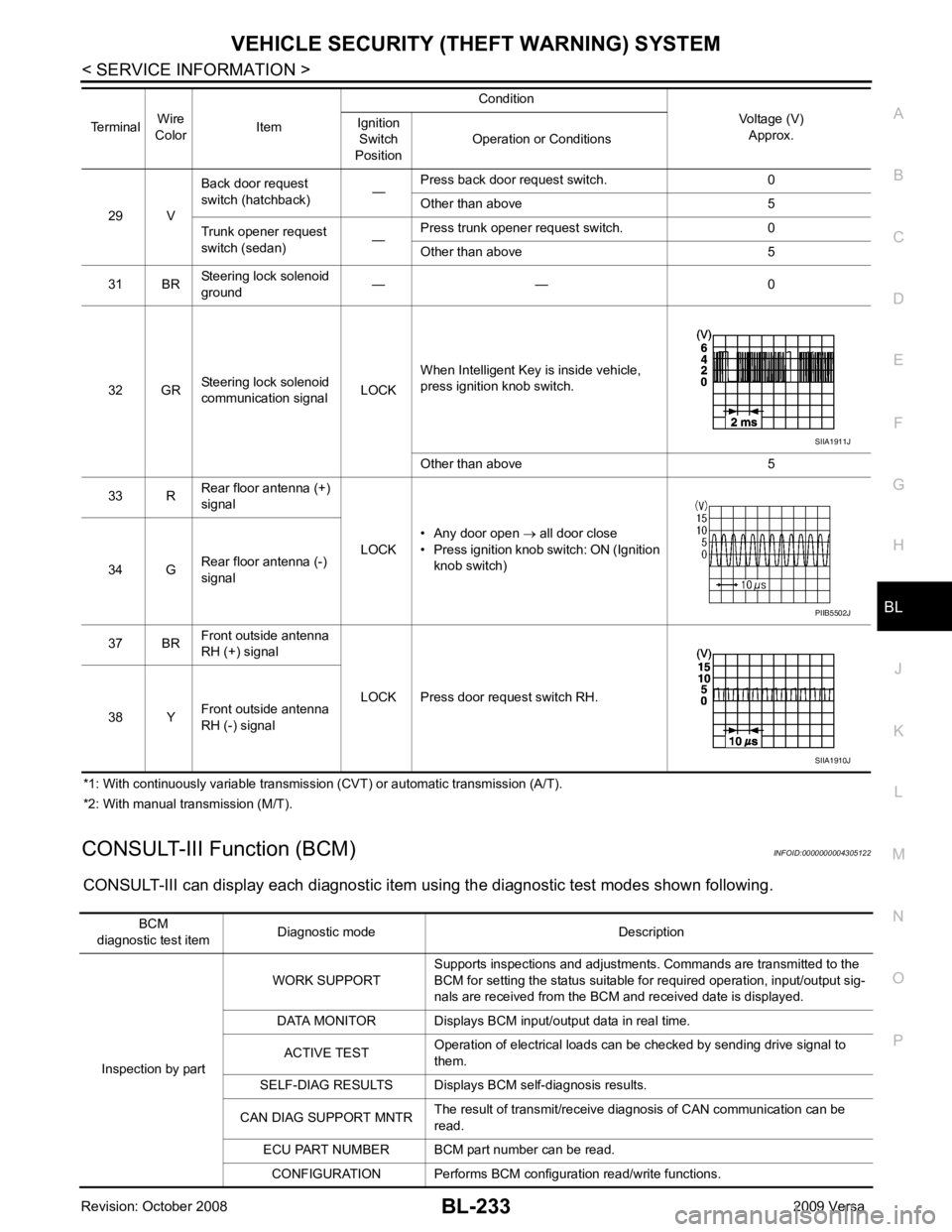
VEHICLE SECURITY (THEFT WARNING) SYSTEM
BL-233
< SERVICE INFORMATION >
C
D E
F
G H
J
K L
M A
B BL
N
O P
*1: With continuously variable transmission (CVT) or automatic transmission (A/T).
*2: With manual transmission (M/T).
CONSULT-III Function (BCM) INFOID:0000000004305122
CONSULT-III can display each diagnostic item using the diagnostic test modes shown following. 29 V
Back door request
switch (hatchback) —Press back door request switch. 0
Other than above 5
Trunk opener request
switch (sedan) —Press trunk opener request switch. 0
Other than above 5
31 BR Steering lock solenoid
ground — — 0
32 GR Steering lock solenoid
communication signal LOCKWhen Intelligent Key is inside vehicle,
press ignition knob switch.
Other than above 5
33 R Rear floor antenna (+)
signal
LOCK• Any door open
→ all door close
• Press ignition knob switch: ON (Ignition
knob switch)
34 G Rear floor antenna (-)
signal
37 BR Front outside antenna
RH (+) signal
LOCK Press door request switch RH.
38 Y Front outside antenna
RH (-) signal
Terminal
Wire
Color Item Condition
Voltage (V)Approx.
Ignition
Switch
Position Operation or Conditions SIIA1911J
PIIB5502J
SIIA1910J
BCM
diagnostic test item Diagnostic mode Description
Inspection by part WORK SUPPORT
Supports inspections and adjustments. Commands are transmitted to the
BCM for setting the status suitable for required operation, input/output sig-
nals are received from the BCM and received date is displayed.
DATA MONITOR Displays BCM input/output data in real time.
ACTIVE TEST Operation of electrical loads can be checked by sending drive signal to
them.
SELF-DIAG RESULTS Displays BC M self-diagnosis results.
CAN DIAG SUPPORT MNTR The result of transmit/receive diagnosis of CAN communication can be
read.
ECU PART NUMBER BCM part number can be read.
CONFIGURATION Performs BCM configuration read/write functions.