2009 NISSAN LATIO automatic transmission
[x] Cancel search: automatic transmissionPage 959 of 4331
![NISSAN LATIO 2009 Service Repair Manual PRECAUTIONS
CVT-15
< SERVICE INFORMATION >
[RE0F08A] D
E
F
G H
I
J
K L
M A
B CVT
N
O P
•
Before replacing TCM, perform TCM input/output signal
inspection and make sure whether TCM functions pr NISSAN LATIO 2009 Service Repair Manual PRECAUTIONS
CVT-15
< SERVICE INFORMATION >
[RE0F08A] D
E
F
G H
I
J
K L
M A
B CVT
N
O P
•
Before replacing TCM, perform TCM input/output signal
inspection and make sure whether TCM functions pr](/manual-img/5/57359/w960_57359-958.png)
PRECAUTIONS
CVT-15
< SERVICE INFORMATION >
[RE0F08A] D
E
F
G H
I
J
K L
M A
B CVT
N
O P
•
Before replacing TCM, perform TCM input/output signal
inspection and make sure whether TCM functions properly or
not. CVT-49, " TCM Terminal and Reference Value " .
• After performing each TROUBL E DIAGNOSIS, perform “DTC
Confirmation Procedure”.
If the repair is completed the DTC should not be displayed in
the “DTC Confirmation Procedure”.
• Always use the specified br and of CVT fluid. Refer to MA-14, " Flu-
ids and Lubricants " .
• Use lint-free paper, not cloth rags, during work.
• After replacing the CVT fluid, dispose of the waste oil using the methods prescribed by law, ordinance, etc.
Service Notice or Precaution INFOID:0000000004666859
CVT FLUID COOLER SERVICE If CVT fluid contains friction material (clutches, brakes , etc.), or if an CVT is replaced, inspect and clean the
CVT fluid cooler mounted in the radiator or replace t he radiator. Flush cooler lines using cleaning solvent and
compressed air after repair. For CVT fluid cooler cleaning procedure, refer to CVT-18, " CVT Fluid Cooler
Cleaning " . For radiator replacement, refer to
CO-38 .
OBD-II SELF-DIAGNOSIS • CVT self-diagnosis is performed by the TCM in comb ination with the ECM. The results can be read through
the blinking pattern of the malfunction indi cator lamp (MIL). Refer to the table on CVT-51, " CONSULT-III
Function (TRANSMISSION) " for the indicator used to display each self-diagnostic result.
• The self-diagnostic results indicated by the MIL ar e automatically stored in both the ECM and TCM memo-
ries.
Always perform the procedure on CVT-30, " OBD-II Diagnostic Trouble Code (DTC) " to complete the
repair and avoid unnecessary blinking of the MIL.
For details of OBD-II, refer to EC-541, " Introduction " .
• Certain systems and components, especially those re lated to OBD, may use the new style slide-lock-
ing type harness connector. For descripti on and how to disconnect, refer to PG-64 . MEF040DA
SEF217U
Page 974 of 4331
" CONSULT-III Function (TRANSMISSION) " .
OBD-II Function for CVT System INFOID:0000000004666876
The ECM provides emission-related on board diagnostic (O BD-II) functions for the CVT system. One function
is to receive a signal from the TCM used with OBD-relat ed parts of the CVT system. The signal is sent to the
ECM when a malfunction occurs in the corresponding OBD-re lated part. The other function is to indicate a
diagnostic result by means of the MIL (malfunction indi cator lamp) on the instrument panel. Sensors, switches
and solenoid valves are used as sensing elements.
The MIL automatically illuminates in One or Two Trip Detection Logic when a malfunction is sensed in relation
to CVT system parts.
One or Two Trip Detection Logic of OBD-II INFOID:0000000004666877
ONE TRIP DETECTION LOGIC
If a malfunction is sensed during the first test drive, the MIL will illuminate and the malfunction will be stored in
the ECM memory as a DTC. The TCM is not provided with such a memory function.
TWO TRIP DETECTION LOGIC
When a malfunction is sensed during the first test drive, it is stored in the ECM memory as a 1st trip DTC
(diagnostic trouble code) or 1st trip freeze frame data. At this point, the MIL will not illuminate. — 1st trip
If the same malfunction as that experienced during the fi rst test drive is sensed during the second test drive,
the MIL will illuminate. — 2nd trip
The “trip” in the “One or Two Trip Detection Logic” means a driving mode in which self-diagnosis is performed
during vehicle operation.
OBD-II Diagnostic Trouble Code (DTC) INFOID:0000000004666878
HOW TO READ DTC AND 1ST TRIP DTC
DTC and 1st trip DTC can be read by the following methods.
( with CONSULT-III or GST) CONSULT-III or GST (Generic Scan Tool) Examples: P0705, P0720 etc.
These DTC are prescribed by SAE J2012.
(CONSULT-III also displays the malfunctioning component or system.)
• 1st trip DTC No. is the same as DTC No.
• Output of the diagnostic troubl e code indicates that the indicated circuit has a malfunction. How-
ever, in case of the Mode II and GST, they do not indicate whether the malfunction is still occurring or
occurred in the past and returned to normal.
CONSULT-III can identify them as shown below, therefore, CONSULT-III (if available) is recom-
mended.
DTC or 1st trip DTC of a malfunction is displayed in SELF-DIAGNOSTIC RESULTS mode for “ENGINE” with
CONSULT-III. Time data indicates how many times the vehicle was driven after the last detection of a DTC.
If the DTC is being detected currently, the time data will be “0”.
If a 1st trip DTC is stored in the ECM, the time data will be “1t”. Freeze Frame Data and 1st Trip Freeze Frame Data
Page 1138 of 4331
CONSULT-III
Function (TRANSMISSION) " for the indicator used to display each self-diagnostic result.
• The self-diagnostic results indicated by the MIL ar e automatically stored in both the ECM and TCM memo-
ries.
Always perform the procedure on CVT-209, " OBD-II Diagnostic Trouble Code (DTC) " to complete the
repair and avoid unnecessary blinking of the MIL.
For details of OBD-II, refer to EC-1051, " Introduction " .
• Certain systems and components, esp ecially those related to OBD, may use the new style slide-lock-
ing type harness connector. For descrip tion and how to disconnect, refer to PG-64 .
Page 1153 of 4331
CVT
N
O P
ON BOARD DIAGNOSTIC (OBD) SYSTEM
Introduction INFOID:0000000004305583
The CVT system has two self-diagnostic systems.
The first is the emission-related on board diagnostic syst em (OBD-II) performed by the TCM in combination
with the ECM. The malfunction is indicated by the MI L (malfunction indicator lamp) and is stored as a DTC in
the ECM memory, and the TCM memory.
The second is the TCM original self-diagnosis perform ed by the TCM. The malfunction is stored in the TCM
memory. The detected items are overlapped with OBD-II self-diagnostic items. For detail, refer to CVT-230," CONSULT-III Function (TRANSMISSION) " .
OBD-II Function for CVT System INFOID:0000000004305584
The ECM provides emission-related on board diagnostic (O BD-II) functions for the CVT system. One function
is to receive a signal from the TCM used with OBD-relat ed parts of the CVT system. The signal is sent to the
ECM when a malfunction occurs in the corresponding OBD-re lated part. The other function is to indicate a
diagnostic result by means of the MIL (malfunction indica tor lamp) on the instrument panel. Sensors, switches
and solenoid valves are used as sensing elements.
The MIL automatically illuminates in One or Two Trip Detection Logic when a malfunction is sensed in relation
to CVT system parts.
One or Two Trip Detection Logic of OBD-II INFOID:0000000004305585
ONE TRIP DETECTION LOGIC If a malfunction is sensed during the first test drive, the MIL will illuminate and the malfunction will be stored in
the ECM memory as a DTC. The TCM is not provided with such a memory function.
TWO TRIP DETECTION LOGIC When a malfunction is sensed during the first test drive, it is stored in the ECM memory as a 1st trip DTC
(diagnostic trouble code) or 1st trip freeze frame data. At this point, the MIL will not illuminate. — 1st trip
If the same malfunction as that experienced during the fi rst test drive is sensed during the second test drive,
the MIL will illuminate. — 2nd trip
The “trip” in the “One or Two Trip Detection Logic” m eans a driving mode in which self-diagnosis is performed
during vehicle operation.
OBD-II Diagnostic Trouble Code (DTC) INFOID:0000000004305586
HOW TO READ DTC AND 1ST TRIP DTC DTC and 1st trip DTC can be read by the following methods.
( with CONSULT-III or GST) CONSULT-III or GST (Generic Scan Tool) Examples: P0705, P0720 etc.
These DTC are prescribed by SAE J2012.
(CONSULT-III also displays the malfunctioning component or system.)
• 1st trip DTC No. is the same as DTC No.
• Output of the diagnostic troubl e code indicates that the indicated circuit has a malfunction. How-
ever, in case of the Mode II and GST, they do not indicate whether the malfunction is still occurring or
occurred in the past and returned to normal.
CONSULT-III can identify them as shown below, therefore, CONS ULT-III (if available) is recom-
mended.
DTC or 1st trip DTC of a malfunction is displayed in SELF-DIAGNOSTIC RESULTS mode for “ENGINE” with
CONSULT-III. Time data indicates how many times the vehicle was driven after the last detection of a DTC.
If the DTC is being detected curr ently, the time data will be “0”.
If a 1st trip DTC is stored in the ECM, the time data will be “1t”.
Freeze Frame Data and 1st Trip Freeze Frame Data
Page 3256 of 4331
GI
N
O P
2. Use the Intelligent Key or mechanical key to turn the ignition switch to the
″ACC ″ position. At this time, the
steering lock will be released.
3. Disconnect both battery cables. The steering lock will remain released and the steering wheel can be
rotated.
4. Perform the necessary repair operation.
5. When the repair work is completed, return the ignition switch to the ″LOCK ″ position before connecting
the battery cables. (At this time, the steering lock mechanism will engage.)
6. Perform a self-diagnosis check of al l control units using CONSULT-III.
General Precaution INFOID:0000000004307347
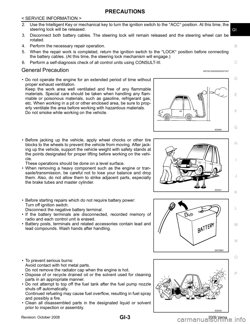
• Do not operate the engine for an extended period of time without proper exhaust ventilation.
Keep the work area well ventilated and free of any flammable
materials. Special care should be taken when handling any flam-
mable or poisonous materials, such as gasoline, refrigerant gas,
etc. When working in a pit or ot her enclosed area, be sure to prop-
erly ventilate the area before working with hazardous materials.
Do not smoke while working on the vehicle.
• Before jacking up the vehicle, apply wheel chocks or other tire blocks to the wheels to prevent t he vehicle from moving. After jack-
ing up the vehicle, support the vehicle weight with safety stands at
the points designated for proper lifting before working on the vehi-
cle.
These operations should be done on a level surface.
• When removing a heavy component such as the engine or tran-
saxle/transmission, be careful not to lose your balance and drop
them. Also, do not allow them to strike adjacent parts, especially
the brake tubes and master cylinder.
• Before starting repairs which do not require battery power: Turn off ignition switch.
Disconnect the negative battery terminal.
• If the battery terminals are disconnected, recorded memory of
radio and each control unit is erased.
• Battery posts, terminals and related accessories contain lead and lead compounds. Wash hands after handling.
• To prevent serious burns: Avoid contact with hot metal parts.
Do not remove the radiator cap when the engine is hot.
• Dispose of or recycle drained oil or the solvent used for cleaning
parts in an appropriate manner.
• Do not attempt to top off the fuel tank after the fuel pump nozzle shuts off automatically.
Continued refueling may cause fuel overflow, resulting in fuel spray
and possibly a fire.
• Clean all disassembled parts in the designated liquid or solvent
prior to inspection or assembly. SGI231
SGI233
Page 3288 of 4331
GI
N
O P
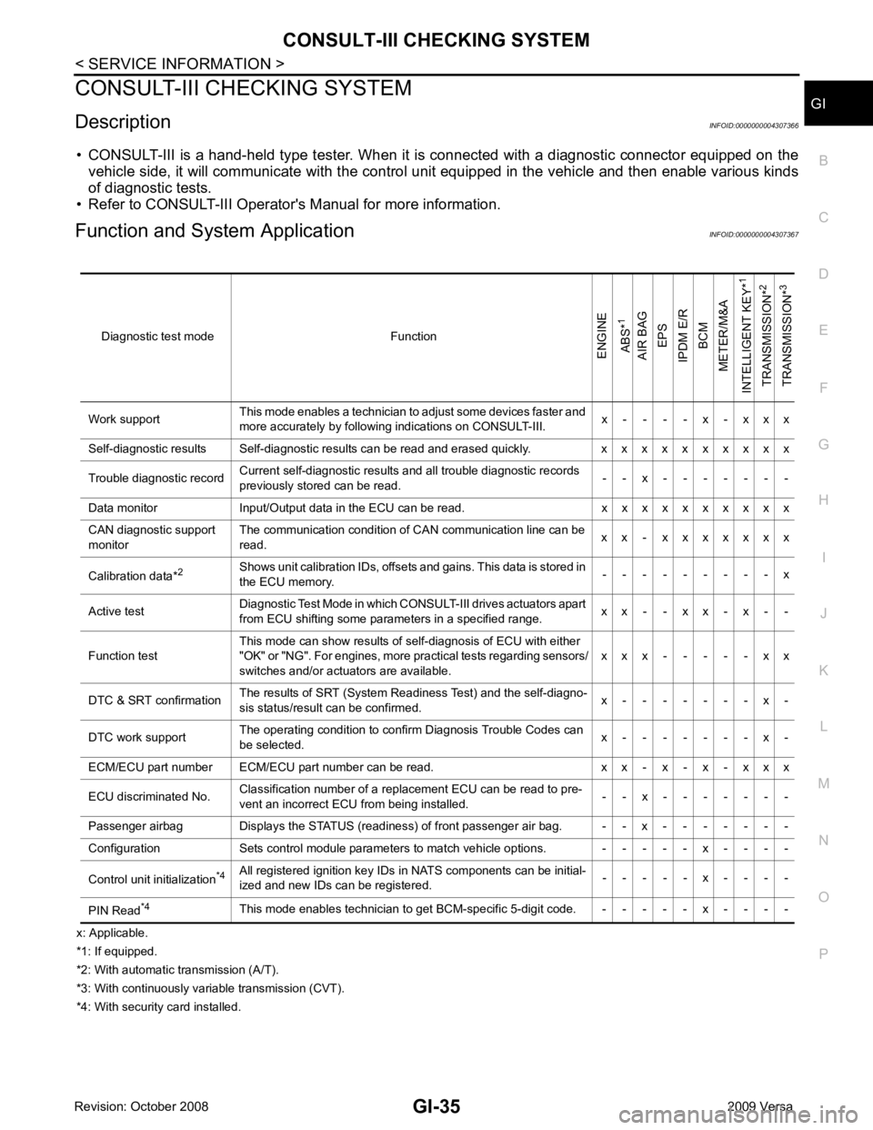
CONSULT-III CHECKING SYSTEM
Description INFOID:0000000004307366
• CONSULT-III is a hand-held type tester. When it is connected with a diagnostic connector equipped on the vehicle side, it will communicate with the contro l unit equipped in the vehicle and then enable various kinds
of diagnostic tests.
• Refer to CONSULT-III Operator's Manual for more information.
Function and System Application INFOID:0000000004307367
x: Applicable.
*1: If equipped.
*2: With automatic transmission (A/T).
*3: With continuously variable transmission (CVT).
*4: With security card installed. Diagnostic test mode FunctionENGINE
ABS* 1
AIR BAG EPS
IPDM E/R BCM
METER/M&A
INTELLIGENT KEY* 1
TRANSMISSION* 2
TRANSMISSION* 3
Work support This mode enables a technician to adjust some devices faster and
more accurately by following indications on CONSULT-III. x - - - - x - x x x
Self-diagnostic results Self-diagnostic results can be read and erased quickly. x x x x x x x x x x
Trouble diagnostic record Current self-diagnostic results and all trouble diagnostic records
previously stored can be read. - - x - - - - - - -
Data monitor Input/Output data in the ECU can be read. x x x x x x x x x x
CAN diagnostic support
monitor The communication condition of CAN communication line can be
read. x x - x x x x x x x
Calibration data* 2
Shows unit calibration IDs, offsets and gains. This data is stored in
the ECU memory. - - - - - - - - - x
Active test Diagnostic Test Mode in which CONSULT-III drives actuators apart
from ECU shifting some parameters in a specified range. x x - - x x - x - -
Function test This mode can show results of self-diagnosis of ECU with either
"OK" or "NG". For engines, more practical tests regarding sensors/
switches and/or actuators are available. x x x - - - - - x x
DTC & SRT confirmation The results of SRT (System Readiness Test) and the self-diagno-
sis status/result can be confirmed. x - - - - - - - x -
DTC work support The operating condition to confirm Diagnosis Trouble Codes can
be selected. x - - - - - - - x -
ECM/ECU part number ECM/ECU part number can be read. x x - x - x - x x x
ECU discriminated No. Classification number of a replacement ECU can be read to pre-
vent an incorrect ECU from being installed. - - x - - - - - - -
Passenger airbag Displays the STATUS (readiness) of front passenger air bag. - - x - - - - - - -
Configuration Sets control module parameters to match vehicle options. - - - - - x - - - -
Control unit initialization *4
All registered ignition key IDs in NATS components can be initial-
ized and new IDs can be registered. - - - - - x - - - -
PIN Read *4
This mode enables technician to get BCM-specific 5-digit code. - - - - - x - - - -
Page 3754 of 4331
MA
N
O P
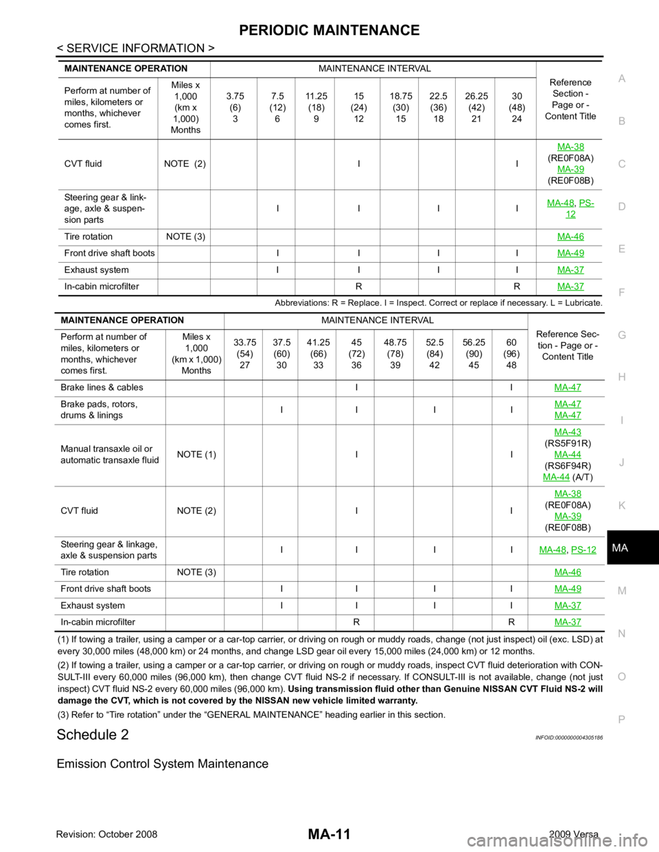
Abbreviations: R = Replace. I = Inspect. Corr
ect or replace if necessary. L = Lubricate.
(1) If towing a trailer, using a camper or a car-top carrier, or driving on rough or muddy roads, change (not just inspect) oil (exc. LSD) at
every 30,000 miles (48,000 km) or 24 months, and change LSD gear oil every 15,000 miles (24,000 km) or 12 months.
(2) If towing a trailer, using a camper or a car-top carrier, or driving on rough or muddy roads, inspect CVT fluid deteriorati on with CON-
SULT-III every 60,000 miles (96,000 km), then change CVT fluid NS-2 if necessary. If CONSULT-III is not available, change (not just
inspect) CVT fluid NS-2 every 60,000 miles (96,000 km). Using transmission fluid other than Genuine NISSAN CVT Fluid NS-2 will
damage the CVT, which is not covered by the NISSAN new vehicle limited warranty.
(3) Refer to “Tire rotation” under the “GENERAL MAINTENANCE” heading earlier in this section.
Schedule 2 INFOID:0000000004305186
Emission Control System Maintenance CVT fluid NOTE (2) I I
MA-38
(RE0F08A) MA-39
(RE0F08B)
Steering gear & link-
age, axle & suspen-
sion parts I I I I
MA-48 ,
PS- 12
Tire rotation NOTE (3)
MA-46Front drive shaft boots I I I I
MA-49Exhaust system I I I I
MA-37In-cabin microfilter R R
MA-37Brake pads, rotors,
drums & linings I I I I MA-47 MA-47
Manual transaxle oil or
automatic transaxle fluid NOTE (1) I I MA-43
(RS5F91R) MA-44
(RS6F94R)
MA-44 (A/T)
CVT fluid NOTE (2) I I MA-38
(RE0F08A)
MA-39
(RE0F08B)
Steering gear & linkage,
axle & suspension parts I I I I
MA-48 ,
PS-12 Tire rotation NOTE (3)
MA-46Front drive shaft boots I I I I
MA-49Exhaust system I I I I
MA-37In-cabin microfilter R R
MA-37