2009 NISSAN LATIO ad blue
[x] Cancel search: ad bluePage 14 of 4331
AT
N
O P
• The valve body contains precision parts and requires extreme care when parts are removed and serviced.
Place disassembled valve body parts in order for easier and proper assembly. Care will also prevent springs
and small parts from becoming scattered or lost.
• Properly installed valves, sleeves, plugs, etc. will slide along bores in valve body under their own weight.
• Before assembly, apply a coat of recommended ATF to all parts. Apply petroleum jelly to protect O-rings and
seals, or hold bearings and washers in pl ace during assembly. Do not use grease.
• Extreme care should be taken to avoid damage to O-rings, seals and gaskets when assembling.
• Clean or replace ATF cooler if excessive foreign material is found in oil pan or clogging strainer. Refer to AT-18, " A/T Fluid Cooler Cleaning " .
• After overhaul, refill the A/T with new ATF.
• When the A/T drain plug is removed, only some of the fluid is drained. Old A/T fluid will remain in torque con- verter and ATF cooling system.
Always follow the procedures under “Changing A/T Fluid” in the AT section when changing A/T fluid. Refer to
AT-17, " Changing A/T Fluid " ,
AT-17, " Checking A/T Fluid " .
Service Notice or Precaution INFOID:0000000004305292
ATF COOLER SERVICE If A/T fluid contains frictional material (clutches, bands, etc.), or if an A/T is repaired, overhauled, or replaced,
inspect and clean the A/T oil cooler mounted in the radiator or replace the radiator. Flush cooler lines using
cleaning solvent and compressed air after repair. Check Serv ice Bulletins for latest A/T oil cooler cleaning pro-
cedure. For radiator replacement, refer to CO-16, " Removal and Installation " (HR16DE engine models),
CO-38, " Removal and Installation " (MR18DE engine models).
TORQUE CONVERTER SERVICE The torque converter should be replaced under any of the following conditions:
• External leaks in the hub weld area.
• Converter hub is scored or damaged.
• Converter pilot is broken, damaged or fits poorly into crankshaft.
• Steel particles are found after flushing the cooler and cooler lines.
• Pump is damaged or steel particles are found in the converter.
• Vehicle has TCC shudder and/or no TCC apply. Replace only after all hydraulic and electrical diagnoses
have been made. (Converter clutch material may be glazed.)
• Converter is contaminated with engi ne coolant containing antifreeze.
• Internal malfunction of stator roller clutch.
• Heavy clutch debris due to overheating (blue converter).
• Steel particles or clutch lining material found in flui d filter or on magnet when no internal parts in unit are
worn or damaged — indicates that lining material came from converter.
The torque converter should not be replaced if:
• The fluid has an odor, is discolored, and there is no evidence of metal or clutch facing particles.
• The threads in one or more of the converter bolt holes are damaged.
• A/T malfunction did not display evidence of damaged or worn internal parts, steel particles or clutch plate lin-
ing material in unit and inside the fluid filter.
• Vehicle has been exposed to high mileage (only). The e xception may be where the torque converter clutch
dampener plate lining has seen excess wear by vehicles operated in heavy and/or constant traffic, such as
taxi, delivery or police use.
OBD-II SELF-DIAGNOSIS • A/T self-diagnosis is performed by the TCM in combination with the ECM. The results can be read through the blinking pattern of the OD OFF indicator lamp or the malfunction indicator lamp (MIL). Refer to the table
on AT-83, " Diagnosis Procedure without CONSULT-III " for the indicator used to display each self-diagnostic
result.
• The self-diagnostic results indicated by the MIL ar e automatically stored in both the ECM and TCM memo-
ries.
Always perform the procedure “HOW TO ERASE DTC” on AT-39, " OBD-II Diagnostic Trouble Code
(DTC) " to complete the repair and avo
id unnecessary blinking of the MIL.
• The following self-diagnostic items can be detected us ing ECM self-diagnostic results mode* only when the
OD OFF indicator lamp does not indicate any malfunctions.
- PNP switch
- A/T 1st, 2nd, 3rd, or 4th gear function
*: For details of OBD-II, refer to AT-39 .
Page 385 of 4331

AV
N
O P
CONTENTS
AUDIO, VISUAL, NAVIGATION & TELEPHONE SYS-
TEM
SERVICE INFORMATION .. ..........................2
PRECAUTIONS .............................................. .....2
Precaution for Supplemental Restraint System
(SRS) "AIR BAG" and "SEAT BELT PRE-TEN-
SIONER" ............................................................. ......
2
PREPARATION .............................................. .....3
Commercial Service Tool .................................... ......3
AUDIO ............................................................ .....4
Component Parts Location .................................. ......4
System Description ............................................. ......4
Schematic ........................................................... ......6
Wiring Diagram - AUDIO - ................................... ......8
Audio Unit (Base System) Harness Connector
Terminal Layout .................................................. ....
16
Terminal and Reference Value for Audio Unit
(Base System) ..................................................... ....
16
Audio Unit (Mid Level and Premium System) Har-
ness Connector Terminal Layout ........................ ....
17
Terminal and Reference Value for Audio Unit (Mid
Level and Premium System) ............................... ....
17
Subwoofer Harness Connector Terminal Layout
(Premium Audio System) .................................... ....
20
Terminal and Reference Value for Subwoofer
(Premium Audio System) .................................... ....
20
Satellite Radio Tuner Ha rness Connector Termi-
nal Layout ............................................................ ....
20
Terminal and Reference Value for Satellite Radio
Tuner ................................................................... ....
21
Trouble Diagnosis ............................................... ....21
Noise Inspection .................................................. ....22
Power Supply Circuit Inspection ......................... ....23
Satellite Radio Tuner (Fac tory Installed) Power
and Ground Supply Circuit Inspection ................. ....
24
Satellite Radio Tuner (Fac tory Installed) Commu-
nication Circuit Inspection ................................... ....
25
Satellite Radio Tuner (Fac tory Installed) Left
Channel Audio Signal Circuit Inspection ............. ....
27 Satellite Radio Tuner (Fac
tory Installed) Right
Channel Audio Signal Circuit Inspection ............. ....
27
Steering Switch Check (With Bluetooth) .............. ....28
Sound Is Not Heard from Front Door Speaker
(Base System) ..................................................... ....
30
Sound Is Not Heard from Rear Door Speaker
(Base System) ..................................................... ....
31
Sound Is Not Heard from Front Door Speaker or
Tweeter (Mid Level and Premium System) .............
32
Sound Is Not Heard from Rear Door Speaker (Mid
Level and Premium System) ............................... ....
33
Sound Is Not Heard from Subwoofer (Premium
System) ............................................................... ....
35
Removal and Installation ..................................... ....37
AUDIO ANTENNA ............................................. 42
Location of Antenna ............................................. ....42
Removal and Installation of Roof Antenna ..............42
TELEPHONE ..................................................... 44
Component Parts and Harness Connector Loca-
tion ....................................................................... ....
44
System Description .............................................. ....44
Wiring Diagram - H/PHON - ................................ ....46
Bluetooth Control Unit Harness Connector Termi-
nal Layout ............................................................ ....
48
Terminal and Reference Value for Bluetooth Con-
trol Unit ................................................................ ....
48
Bluetooth Control Unit Se lf-Diagnosis Function ......49
Workflow .............................................................. ....50
Power Supply and Ground Circuit Inspection for
Bluetooth Control Unit .. ...........................................
50
Basic Inspection of Hands-Free Phone ............... ....51
Steering Wheel Audio Co ntrol Switch Does Not
Operate ................................................................ ....
52
Voice Activated Control Fu nction Does Not Oper-
ate ........................................................................ ....
53
Removal and Installation ..................................... ....55
Page 389 of 4331

AV
N
O P
• to audio unit terminal 21 (with premium system)
• through body grounds M57 and M61 and
• to subwoofer terminal 3 (with premium system)
• through body grounds B7 and B19.
Then audio signals are supplied
• through audio unit terminals 2, 3, 4, 5, 11, 12, 13, and 14
• to terminals + and - of front door speaker LH and RH and
• to terminals + and - of tweeter LH and RH and
• to terminals + and - of rear door speaker LH and RH and
• to terminals 2 and 6 of subwoofer (with premium system).
Steering Wheel Audio Contro l Switches (with Bluetooth)
When one of steering wheel audio control switches is pus hed, the resistance in steering switch circuit changes
depending on which button is pushed.
Satellite Radio Tuner (Pre-wiring) The satellite radio tuner pre-wiring allows connection of a satellite radio tuner.
Power is supplied at all times
• through 20A fuse (No. 27, located in the fuse and fusible link box)
• to satellite radio tuner pre-wiring terminal 32.
With the ignition switch in the ACC or ON position, power is supplied
• through 10A fuse (No. 20, located in the fuse and fusible link box)
• to satellite radio tuner pre-wiring terminal 36.
Then audio signals are supplied
• through satellite radio tuner pre-wiring terminals 21, 22, 23 and 24
• to audio unit terminals 41, 42, 43 and 44.
Satellite Radio Tuner (Factory Installed)
Power is supplied at all times
• through 20A fuse (No. 27, located in the fuse and fusible link box)
• to satellite radio tuner terminal 32.
With the ignition switch in the ACC or ON position, power is supplied
• through 10A fuse (No. 20, located in the fuse and fusible link box)
• to satellite radio tuner terminal 36.
Ground is supplied through the case of the satellite radio tuner.
Then audio signals are supplied
• through satellite radio tuner terminals 21, 22, 23 and 24
• to audio unit terminals 41, 42, 43 and 44.
Ground is supplied through the case of the satellite radio tuner.
SPEED SENSITIVE VOLUME SYSTEM (MID LEVEL AND PREMIUM SYSTEM) Volume level of this system goes up and down automatica lly in proportion to the vehicle speed. The control
level can be selected by the customer. Refer to Owner's Manual for operating instructions.
Page 403 of 4331
AUDIO
AV-19
< SERVICE INFORMATION >
C
D E
F
G H
I
J
L
M A
B AV
N
O P
*1: With premium system
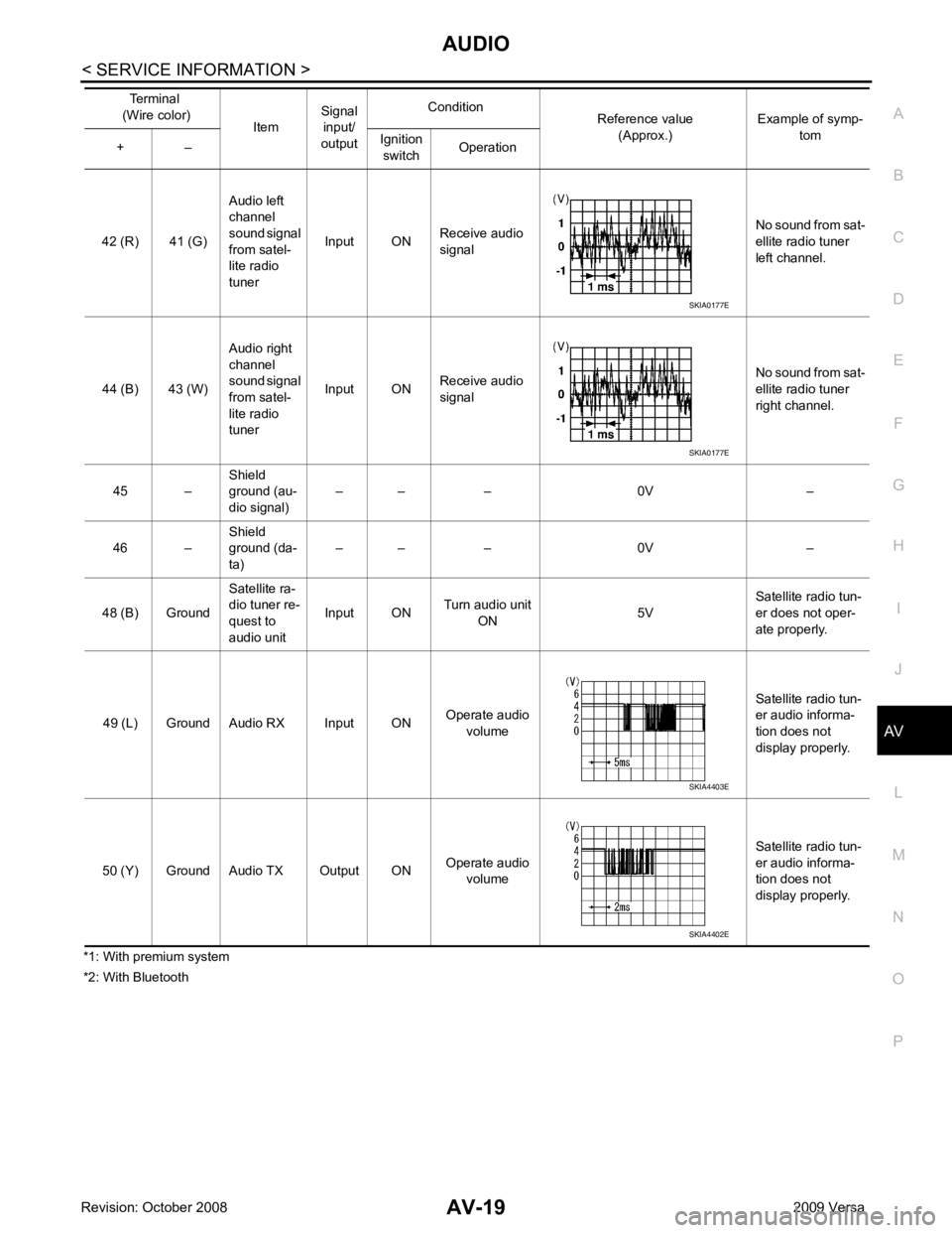
*2: With Bluetooth 42 (R) 41 (G)
Audio left
channel
sound signal
from satel-
lite radio
tuner Input ON
Receive audio
signal No sound from sat-
ellite radio tuner
left channel.
44 (B) 43 (W) Audio right
channel
sound signal
from satel-
lite radio
tuner Input ON
Receive audio
signal No sound from sat-
ellite radio tuner
right channel.
45 – Shield
ground (au-
dio signal) – – – 0V –
46 – Shield
ground (da-
ta) – – – 0V –
48 (B) Ground Satellite ra-
dio tuner re-
quest to
audio unit Input ON
Turn audio unit
ON 5VSatellite radio tun-
er does not oper-
ate properly.
49 (L) Ground Audio RX Input ON Operate audio
volume Satellite radio tun-
er audio informa-
tion does not
display properly.
50 (Y) Ground Audio TX Output ON Operate audio
volume Satellite radio tun-
er audio informa-
tion does not
display properly.
Terminal
(Wire color) ItemSignal
input/
output Condition
Reference value
(Approx.) Example of symp-
tom
+ – Ignition
switch Operation SKIA0177E
SKIA0177E
SKIA4403E
SKIA4402E
Page 412 of 4331
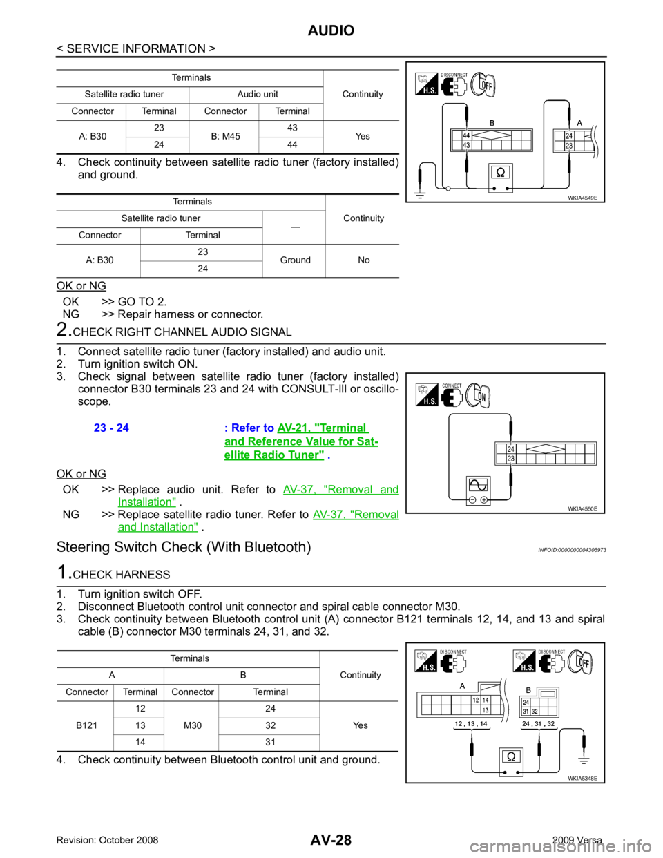
OK >> GO TO 2.
NG >> Repair harness or connector. OK >> Replace audio unit. Refer to
AV-37, " Removal and
Installation " .
NG >> Replace satellite radio tuner. Refer to AV-37, " Removal
and Installation " .
Steering Switch Check (With Bluetooth) INFOID:0000000004306973Terminal
and Reference Value for Sat-
ellite Radio Tuner " .
Page 429 of 4331
AV
N
O P
tooth cellular telephones may not be recognized by t
he Bluetooth control unit. When a cellular telephone or
the Bluetooth control unit is replaced, the telephone must be paired with the Bluetooth control unit. Different
cellular telephones may have different pairing procedures. Refer to the cellular telephone operating manual.
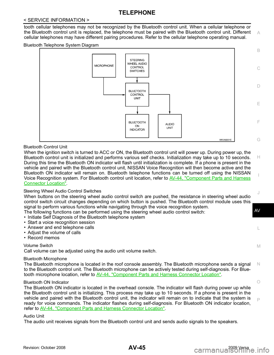
Bluetooth Telephone System Diagram
Bluetooth Control Unit When the ignition switch is turned to ACC or ON, the Bluetooth control unit will power up. During power up, the
Bluetooth control unit is initialized and performs various self checks. Initialization may take up to 10 seconds.
During this time the Bluetooth ON indicator will flash until initialization is complete. If a phone is present in the
vehicle and paired with the Bluetooth control unit, NIS SAN Voice Recognition will then become active and the
Bluetooth ON indicator will remain on. Bluetooth te lephone functions can be turned off using the NISSAN
Voice Recognition system. For Bluetooth control unit location, refer to AV-44, " Component Parts and Harness
Connector Location " .
Steering Wheel Audio Control Switches When buttons on the steering wheel audio control switch are pushed, the resistance in steering wheel audio
control switch circuit changes depending on which button is pushed. The Bluetooth control module uses this
signal to perform various functions while navigating through the voice recognition system.
The following functions can be performed usi ng the steering wheel audio control switch:
• Initiate Self Diagnosis of the Bluetooth telephone system
• Start a voice recognition session
• Answer and end telephone calls
• Adjust the volume of calls
• Record memos
Volume Switch Call volume can be adjusted using the audio unit volume switch.
Bluetooth Microphone The Bluetooth microphone is located in the roof c onsole assembly. The Bluetooth microphone sends a signal
to the Bluetooth control unit. The Bluetooth microphone can be actively tested during self-diagnosis. For Blue-
tooth microphone location, refer to AV-44, " Component Parts and Harness Connector Location " .
Bluetooth ON Indicator The Bluetooth ON indicator is located in the overhead console. The indicator will flash during power up while
the Bluetooth control unit is initializing. This process may take up to 10 seconds. If a phone is present in the
vehicle and paired with the Bluetooth control unit, the indi cator will remain on to indicate that the system is
ready for voice commands. The indicator flashes duri ng self-diagnosis. For Bluetooth ON indicator location,
refer to AV-44, " Component Parts and Harness Connector Location " .
Audio Unit The audio unit receives signals from the Bluetooth control unit and sends audio signals to the speakers.
Page 433 of 4331
AV
N
O P
Bluetooth Control Unit
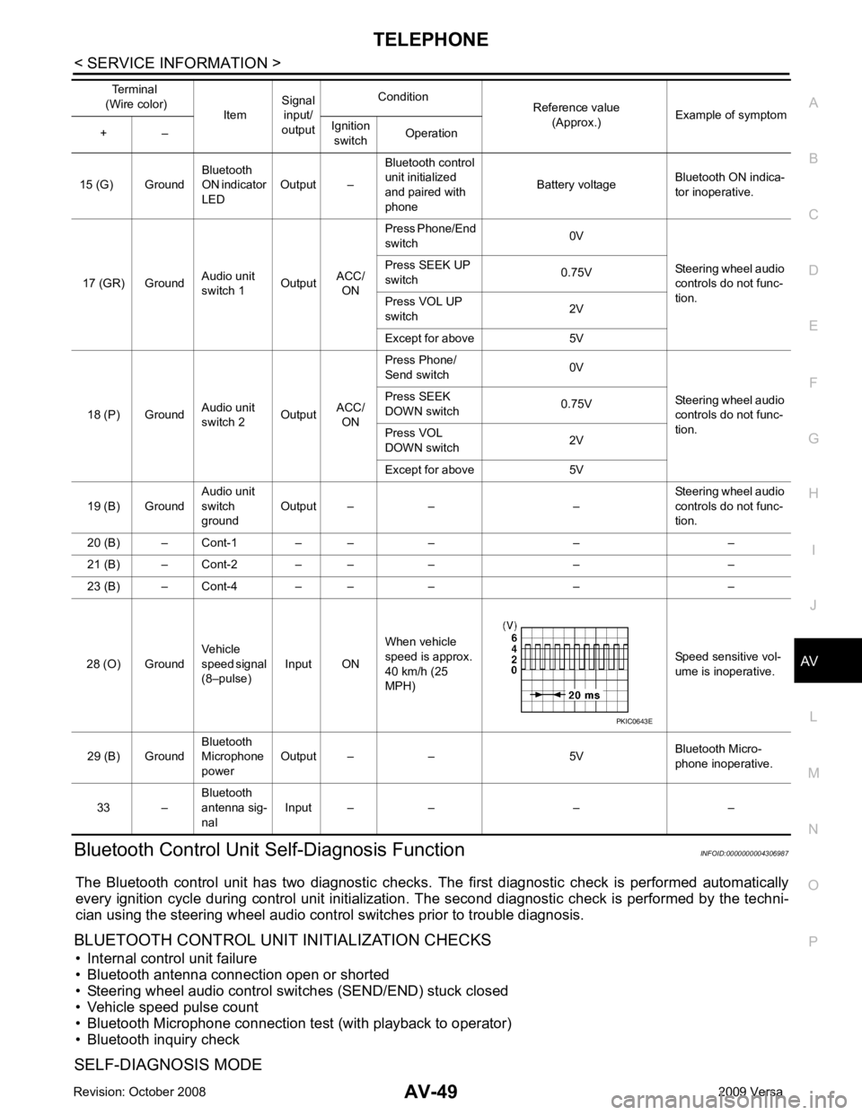
Self-Diagnosis Function INFOID:0000000004306987
The Bluetooth control unit has two diagnostic checks. The first diagnostic check is performed automatically
every ignition cycle during control unit initialization. The second diagnostic check is performed by the techni-
cian using the steering wheel audio control switches prior to trouble diagnosis.
BLUETOOTH CONTROL UNIT INITIALIZATION CHECKS
• Internal control unit failure
• Bluetooth antenna connection open or shorted
• Steering wheel audio control swit ches (SEND/END) stuck closed
• Vehicle speed pulse count
• Bluetooth Microphone connection test (with playback to operator)
• Bluetooth inquiry check
SELF-DIAGNOSIS MODE 15 (G) Ground
Bluetooth
ON indicator
LED Output – Bluetooth control
unit initialized
and paired with
phone Battery voltage
Bluetooth ON indica-
tor inoperative.
17 (GR) Ground Audio unit
switch 1 OutputACC/
ON Press Phone/End
switch 0V
Steering wheel audio
controls do not func-
tion.
Press SEEK UP
switch 0.75V
Press VOL UP
switch 2V
Except for above 5V
18 (P) Ground Audio unit
switch 2 OutputACC/
ON Press Phone/
Send switch 0V
Steering wheel audio
controls do not func-
tion.
Press SEEK
DOWN switch 0.75V
Press VOL
DOWN switch 2V
Except for above 5V
19 (B) Ground Audio unit
switch
ground Output – – – Steering wheel audio
controls do not func-
tion.
20 (B) – Cont-1 – – – – –
21 (B) – Cont-2 – – – – –
23 (B) – Cont-4 – – – – –
28 (O) Ground Vehicle
speed signal
(8–pulse) Input ON When vehicle
speed is approx.
40 km/h (25
MPH) Speed sensitive vol-
ume is inoperative.
29 (B) Ground Bluetooth
Microphone
power Output – – 5V
Bluetooth Micro-
phone inoperative.
33 – Bluetooth
antenna sig-
nal Input – – – –
Terminal
(Wire color) ItemSignal
input/
output Condition
Reference value
(Approx.) Example of symptom
+ – Ignition
switch Operation
Page 434 of 4331
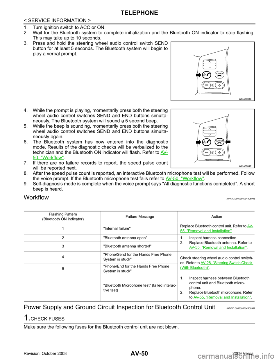
50, " Workflow " .
7. If there are no failure records to report, the speed pulse count will be reported next.
8. After the speed pulse count is reported, an intera ctive Bluetooth microphone test will be performed. Follow
the voice prompt. If the Bluetooth microphone test fails refer to AV-50, " Workflow " .
9. Self-diagnosis mode is complete when the voice prom pt says "All diagnostic functions completed". A short
beep is heard.
Workflow INFOID:0000000004306988
Power Supply and Ground Circuit Ins pection for Bluetooth Control Unit INFOID:0000000004306989 WKIA6004E
55, " Removal and Installation " .
2 "Bluetooth antenna open" 1. Inspect harness connection. 2. Replace Bluetooth antenna. Refer to AV-55, " Removal and Installation " .
3 "Bluetooth antenna shorted"
4 "Phone/Send for the Hands Free Phone
System is stuck" Check steering wheel audio control switch-
es. Refer to AV-28, " Steering Switch Check
(With Bluetooth) " .
5 "Phone/End for the Hands Free Phone
System is stuck"
– "Bluetooth Microphone test" (failed interac-
tive test) 1. Inspect harness between Bluetooth
control unit and Bluetooth micro-
phone.
2. Replace Bluetooth microphone. Refer to AV-55, " Removal and Installation " .