2009 NISSAN LATIO cruise control
[x] Cancel search: cruise controlPage 200 of 4331

AT
N
O P
Is any malfunction detected by self-diagnostic results? YES >> Check the malfuncti
oning system. Refer to AT-79, " CONSULT-III Functi
on (TRANSMISSION) " or
AT-83, " Diagnosis Procedure without CONSULT-III " .
NO >> GO TO 2. Description " (HR16DE),
EC-959, " Component
Description " (MR Type 1) or
EC-1481, " Component Description " (MR Type 2).
OK or NG OK >> GO TO 3.
NG >> Repair or replace accelerator pedal position sensor. Control Valve Assembly and Accumulators " .
2. Check following items:
- Torque converter clutch control valve
- Torque converter clutch solenoid valve
- Torque converter relief valve
- Pilot valve
- Pilot filter
3. Disassemble A/T. Refer to AT-256, " Disassembly " .
4. Check the following items:
- Torque converter. Refer to AT-256, " Disassembly " .
OK or NG OK >> GO TO 4.
NG >> Repair or replace damaged parts. Cruise Test - Part 1 " .
OK or NG OK >>
INSPECTION END
NG >> GO TO 5. TCM Terminal and Reference Value " .
2. If NG, recheck TCM pin terminals for dam age or loose connection with harness connector.
OK or NG OK >>
INSPECTION END
NG >> Repair or replace damaged parts.
A/T Does Not Hold Lock-up Condition INFOID:0000000004305484
SYMPTOM: A/T does not hold lock-up condition for more than 30 second s on “Cruise Test — Part 1”.
DIAGNOSTIC PROCEDURE CONSULT-III Functi
on (TRANSMISSION) " or
AT-83, " Diagnosis Pro-
cedure without CONSULT-III " .
Is any malfunction detected by self-diagnostic results? YES >> Check the malfuncti
oning system. Refer to AT-79, " CONSULT-III Functi
on (TRANSMISSION) " or
AT-83, " Diagnosis Procedure without CONSULT-III " .
NO >> GO TO 2. Component " .
2. Check A/T fluid condition. Refer to AT-51, " Inspections Before Trouble Diagnosis " .
Page 201 of 4331
OK >> GO TO 4.
NG >> GO TO 3. Control Valve Assembly and Accumulators " .
2. Check the following items:
- Torque converter clutch control valve
- Torque converter clutch solenoid valve
- Pilot valve
- Pilot filter
3. Disassemble A/T. Refer to AT-256, " Disassembly " .
4. Check the following items:
- Torque converter. Refer to AT-256, " Disassembly " .
- Oil pump assembly. Refer to AT-277, " Oil Pump " .
OK or NG OK >> GO TO 5.
NG >> Repair or replace damaged parts. Control Valve Assembly and Accumulators " .
2. Check the following items:
- Torque converter clutch control valve
- Torque converter clutch solenoid valve
- Pilot valve
- Pilot filter
OK or NG OK >> GO TO 5.
NG >> Repair or replace damaged parts. Cruise Test - Part 1 " .
OK or NG OK >>
INSPECTION END
NG >> GO TO 6. TCM Terminal and Reference Value " .
2. If NG, recheck TCM pin terminals for damage or loose connection with harness connector.
OK or NG OK >>
INSPECTION END
NG >> Repair or replace damaged parts.
Lock-up Is Not Released INFOID:0000000004305485
SYMPTOM:
Lock-up is not released when accelerator pedal is released on “Cruise Test — Part 1”.
DIAGNOSTIC PROCEDURE CONSULT-III Functi
on (TRANSMISSION) " or
AT-83, " Diagnosis Pro-
cedure without CONSULT-III " .
Is any malfunction detected by self-diagnostic results?YES >> Check the malfunctioning system. Refer to
AT-79, " CONSULT-III Function (TRANSMISSION) " or
AT-83, " Diagnosis Procedure without CONSULT-III " .
NO >> GO TO 2.
Page 202 of 4331
AT
N
O P
Check again. Refer to
AT-58, " Cruise Test - Part 1 " .
OK or NG OK >>
INSPECTION END
NG >> GO TO 3. TCM Terminal and Reference Value " .
2. If NG, recheck TCM pin terminals for dam age or loose connection with harness connector.
OK or NG OK >>
INSPECTION END
NG >> Repair or replace damaged parts.
Engine Speed Does Not Return to Idle (Light Braking D4→ D 3) INFOID:0000000004305486
SYMPTOM: Engine speed does not smoothly return to idle when A/T shifts from D4 to D 3 on “Cruise Test — Part
1”.
DIAGNOSTIC PROCEDURE CONSULT-III Functi
on (TRANSMISSION) " or
AT-83, " Diagnosis Pro-
cedure without CONSULT-III " .
Is any malfunction detected by self-diagnostic results? YES >> Check the malfuncti
oning system. Refer to AT-79, " CONSULT-III Functi
on (TRANSMISSION) " or
AT-83, " Diagnosis Procedure without CONSULT-III " .
NO >> GO TO 2. Description " (HR16DE),
EC-959, " Component
Description " (MR Type 1) or
EC-1481, " Component Description " (MR Type 2).
OK or NG OK >> GO TO 3.
NG >> Repair or replace accelerator pedal position sensor. Component " .
2. Check A/T fluid condition. Refer to AT-51, " Inspections Before Trouble Diagnosis " .
OK or NG OK >> GO TO 5.
NG >> GO TO 4. Control Valve Assembly and Accumulators " .
2. Check the following items:
- Overrun clutch control valve
- Overrun clutch reducing valve
- Overrun clutch solenoid valve
3. Disassemble A/T. Refer to AT-256, " Disassembly " .
4. Check the following items:
- Overrun clutch assembly. Refer to AT-306, " Forward and Overrun Clutches " .
OK or NG OK >> GO TO 6.
NG >> Repair or replace damaged parts. Control Valve Assembly and Accumulators " .
2. Check the following items:
Page 204 of 4331
TROUBLE DIAGNOSIS FOR SYMPTOMS
AT-199
< SERVICE INFORMATION >
D
E
F
G H
I
J
K L
M A
B AT
N
O P
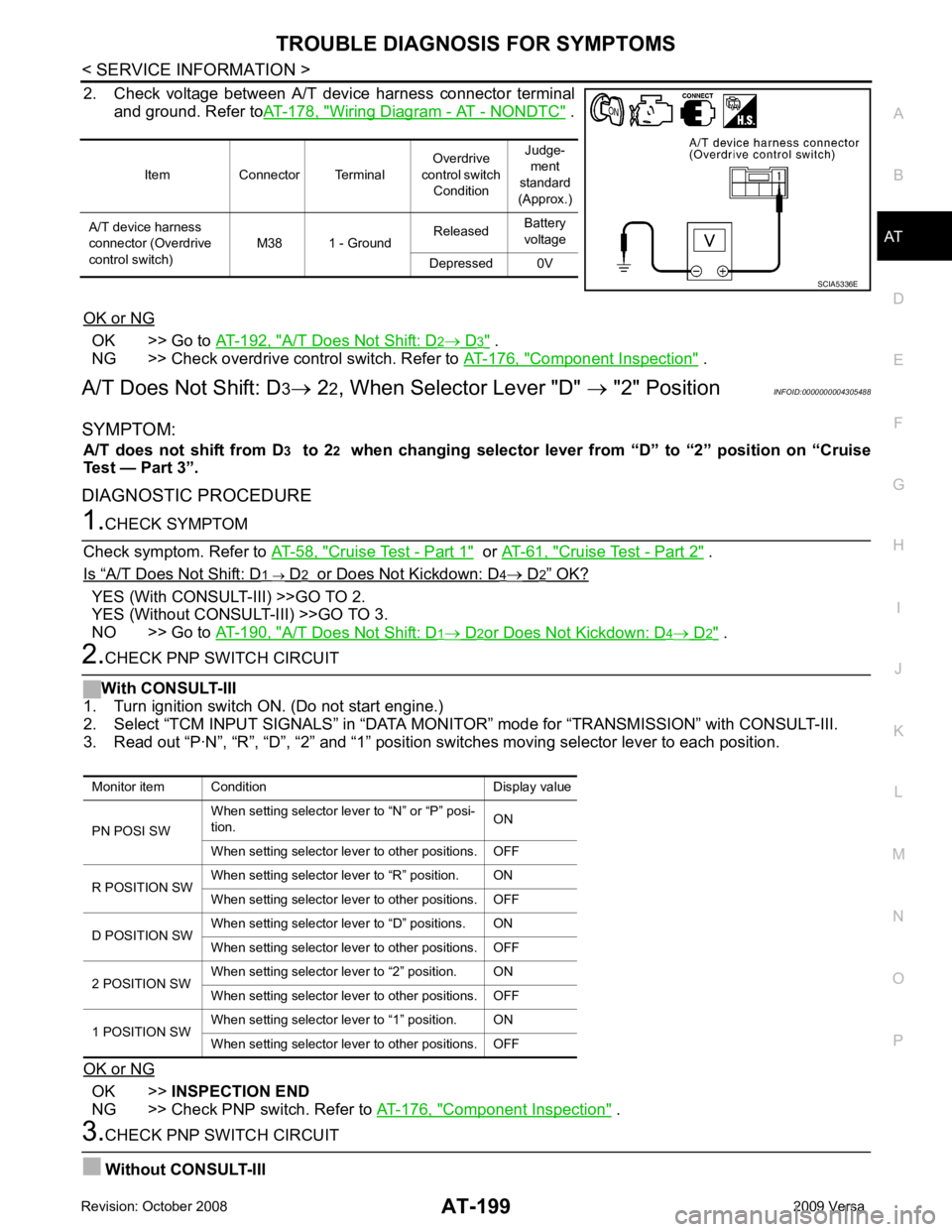
2. Check voltage between A/T device harness connector terminal
and ground. Refer to AT-178, " Wiring Diagram - AT - NONDTC " .
OK or NG OK >> Go to
AT-192, " A/T Does Not Shift: D 2 → D 3 " .
NG >> Check overdrive control switch. Refer to AT-176, " Component Inspection " .
A/T Does Not Shift: D 3→ 22, When Selector Lever "D" → "2" Position INFOID:0000000004305488
SYMPTOM: A/T does not shift from D 3 to 2 2 when changing selector lever from “D” to “2” position on “Cruise
Test — Part 3”.
DIAGNOSTIC PROCEDURE 1.
CHECK SYMPTOM
Check symptom. Refer to AT-58, " Cruise Test - Part 1 " or
AT-61, " Cruise Test - Part 2 " .
Is “ A/T Does Not Shift: D 1 → D 2 or Does Not Kickdown: D 4 → D 2 ” OK?
YES (With CONSULT-III) >>GO TO 2.
YES (Without CONSULT-III) >>GO TO 3.
NO >> Go to AT-190, " A/T Does Not Shift: D 1 → D 2 or Does Not Kickdown: D 4 → D 2 " .
2.
CHECK PNP SWITCH CIRCUIT
With CONSULT-III
1. Turn ignition switch ON. (Do not start engine.)
2. Select “TCM INPUT SIGNALS” in “DATA MONI TOR” mode for “TRANSMISSION” with CONSULT-III.
3. Read out “P·N”, “R”, “D”, “2” and “1” position switches moving selector lever to each position.
OK or NG OK >>
INSPECTION END
NG >> Check PNP switch. Refer to AT-176, " Component Inspection " .
3.
CHECK PNP SWITCH CIRCUIT
Without CONSULT-III Item Connector Terminal
Overdrive
control switch Condition Judge-
ment
standard
(Approx.)
A/T device harness
connector (Overdrive
control switch) M38 1 - Ground
Released
Battery
voltage
Depressed 0V SCIA5336E
Monitor item Condition Display value
PN POSI SW When setting selector le
ver to “N” or “P” posi-
tion. ON
When setting selector lever to other positions. OFF
R POSITION SW When setting selector lever to “R” position. ON
When setting selector lever to other positions. OFF
D POSITION SW When setting selector lever to “D” positions. ON
When setting selector lever to other positions. OFF
2 POSITION SW When setting selector lever to “2” position. ON
When setting selector lever to other positions. OFF
1 POSITION SW When setting selector lever to “1” position. ON
When setting selector lever to other positions. OFF
Page 207 of 4331
AT-202< SERVICE INFORMATION >
TROUBLE DIAGNOSIS FOR SYMPTOMS
- Shift valve A
- Shift solenoid valve A
- Overrun clutch control valve
- Overrun clutch solenoid valve
3. Disassemble A/T. Refer to AT-256, " Disassembly " .
4. Check the following items:
- Servo piston assembly
- Brake band
OK or NG OK >> GO TO 7.
NG >> Repair or replace damaged parts. 7.
CHECK SYMPTOM
Check again. Refer to AT-62, " Cruise Test - Part 3 " .
OK or NG OK >>
INSPECTION END
NG >> GO TO 8. 8.
CHECK TCM
1. Check TCM input/output signals. Refer to AT-77, " TCM Terminal and Reference Value " .
2. If NG, recheck TCM pin terminals for damage or loose connection with harness connector.
OK or NG OK >>
INSPECTION END
NG >> Repair or replace damaged parts.
Vehicle Does Not Decele rate by Engine Brake INFOID:0000000004305490
SYMPTOM:
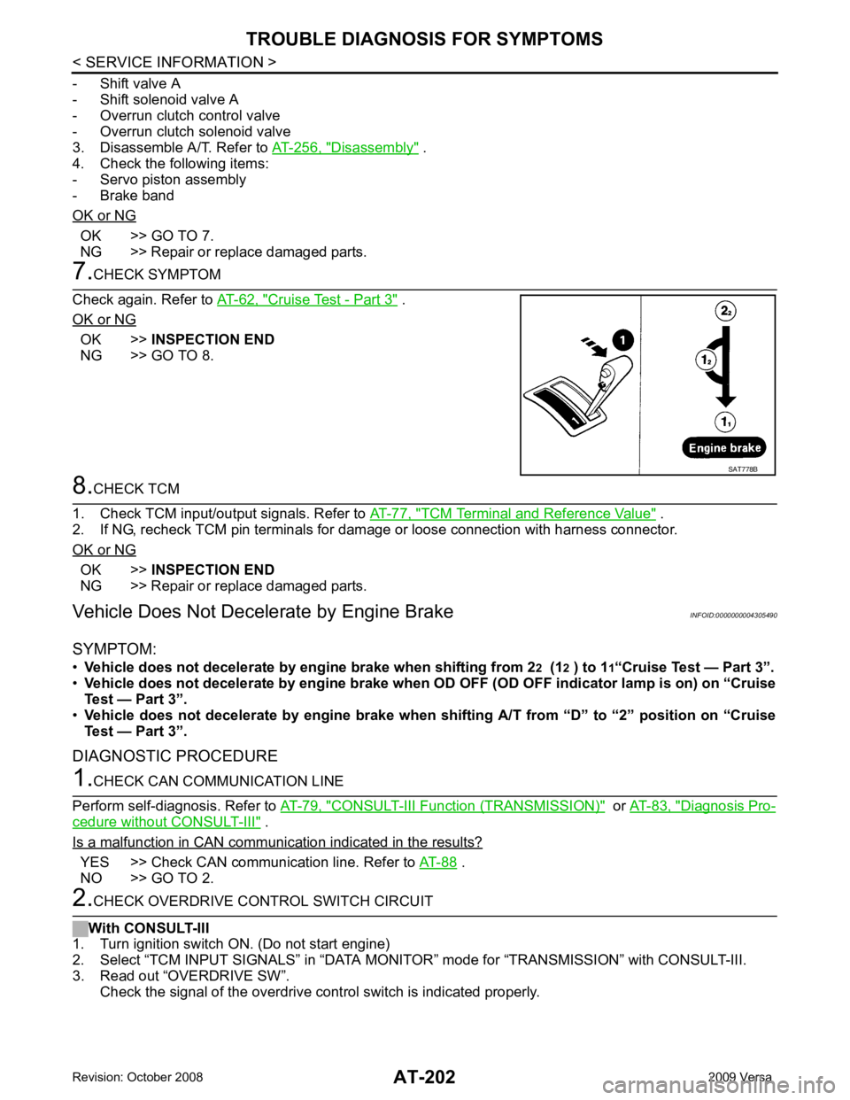
• Vehicle does not decelerate by engi ne brake when shifting from 22 (1 2 ) to 1 1“Cruise Test — Part 3”.
• Vehicle does not decelerate by engine brake when OD OFF (OD OFF indicator lamp is on) on “Cruise
Test — Part 3”.
• Vehicle does not decelerate by engi ne brake when shifting A/T from “D” to “2” position on “Cruise
Test — Part 3”.
DIAGNOSTIC PROCEDURE 1.
CHECK CAN COMMUNICATION LINE
Perform self-diagnosis. Refer to AT-79, " CONSULT-III Functi
on (TRANSMISSION) " or
AT-83, " Diagnosis Pro-
cedure without CONSULT-III " .
Is a malfunction in CAN communication indicated in the results? YES >> Check CAN communication line. Refer to
AT-88 .
NO >> GO TO 2. 2.
CHECK OVERDRIVE CONTROL SWITCH CIRCUIT
With CONSULT-III
1. Turn ignition switch ON. (Do not start engine)
2. Select “TCM INPUT SIGNALS” in “DATA MONITO R” mode for “TRANSMISSION” with CONSULT-III.
3. Read out “OVERDRIVE SW”. Check the signal of the overdrive c ontrol switch is indicated properly. SAT778B
Page 210 of 4331
AT
N
O P
2. Check the following.
- Shift valve A
- Overrun clutch solenoid valve
3. Disassemble A/T. Refer to AT-256, " Disassembly " .
4. Check the following.
- Overrun clutch assembly. Refer to AT-306, " Forward and Overrun Clutches " .
- Low & reverse brake assembly. Refer to AT-313, " Low & Reverse Brake " .
OK or NG OK >> GO TO 10.
NG >> Repair or replace damaged parts. Cruise Test - Part 3 " .
OK or NG OK >>
INSPECTION END
NG >> GO TO 11. TCM Terminal and Reference Value " .
2. If NG, recheck TCM pin terminals for dam age or loose connection with harness connector.
OK or NG OK >>
INSPECTION END
NG >> Repair or replace damaged parts.
TCM Self-Diagnosis Does Not Activate INFOID:0000000004305491
SYMPTOM: OD OFF indicator lamp does not come on in TCM sel f-diagnostic procedure even if the lamp circuit is
good.
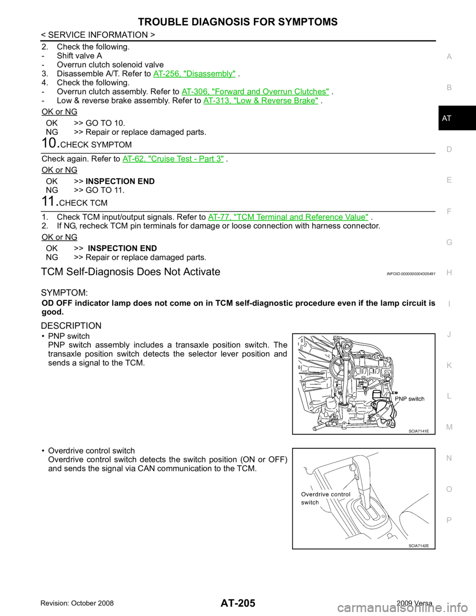
DESCRIPTION • PNP switch PNP switch assembly includes a transaxle position switch. The
transaxle position switch detects the selector lever position and
sends a signal to the TCM.
• Overdrive control switch Overdrive control switch detects the switch position (ON or OFF)
and sends the signal via CAN communication to the TCM.
Page 945 of 4331
CVT
N
O P
CONTENTS
CVT
RE0F08A
SERVICE INFORMATION .. ..........................
9
INDEX FOR DTC ............................................ .....9
Alphabetical Index ............................................... ......9
DTC No. Index .................................................... ......9
PRECAUTIONS .............................................. ....11
Precaution for Supplemental Restraint System
(SRS) "AIR BAG" and "SEAT BELT PRE-TEN-
SIONER" ............................................................. ....
11
Precaution Necessary fo r Steering Wheel Rota-
tion After Battery Disconnect ............................... ....
11
Precaution for On Board Diagnosis (OBD) System
of CVT and Engine .............................................. ....
12
Service After Replacing TCM and Transaxle As-
sembly ................................................................. ....
12
Removal and Installation Procedure for CVT Unit
Connector ............................................................ ....
13
Precaution ........................................................... ....14
Service Notice or Precaution ............................... ....15
PREPARATION .............................................. ....16
Special Service Tool ........................................... ....16
Commercial Service Tool .................................... ....16
CVT FLUID ..................................................... ....17
Checking CVT Fluid ............................................ ....17
Changing CVT Fluid ............................................ ....18
CVT Fluid Cooler Cleanin g .....................................18
CVT SYSTEM ... .............................................. ....22
Cross-Sectional View - RE0F08A ....................... ....22
Control System .................................................... ....23
Hydraulic Control System ........................................24
TCM Function ...................................................... ....24
CAN Communication ........................................... ....25
Input/Output Signal of TCM ................................. ....26
Line Pressure and Secondary Pressure Control . ....26
Shift Control ........................................................ ....27
Lock-up and Select Control ................................. ....28 Control Valve .......................................................
....29
ON BOARD DIAGNOSTIC (OBD) SYSTEM .... 30
Introduction .......................................................... ....30
OBD-II Function for CVT System ........................ ....30
One or Two Trip Detection Logic of OBD-II ......... ....30
OBD-II Diagnostic Trouble Code (DTC) .............. ....30
Malfunction Indicator Lamp (MIL) ............................31
TROUBLE DIAGNOSIS .................................... 33
DTC Inspection Priority Chart .............................. ....33
Fail-Safe .............................................................. ....33
How to Perform Trouble Diagnosis for Quick and
Accurate Repair ................................................... ....
34
CVT Electrical Parts Location .............................. ....39
Circuit Diagram .................................................... ....40
Inspections before Trouble Diagnosis ................. ....40
Road Test ............................................................ ....44
Check before Engine Is Started ........................... ....45
Check at Idle ........................................................ ....45
Cruise Test .......................................................... ....47
Vehicle Speed When Shifting Gears ................... ....49
TCM Terminal and Refere nce Value .......................49
CONSULT-III Function (TRANSMISSION) .......... ....51
Diagnosis Procedure withou t CONSULT-III ............59
DTC U1000 CAN COMMUNICATION LINE ..... 60
Description ........................................................... ....60
On Board Diagnosis Logic ................................... ....60
Possible Cause .................................................... ....60
DTC Confirmation Procedure .............................. ....60
Wiring Diagram - CVT - CAN ............................... ....61
Diagnosis Procedure ........................................... ....62
DTC U1010 TRANSMISSION CONTROL
MODULE (CAN) ................................................ 63
Description ........................................................... ....63
On Board Diagnosis Logic ................................... ....63
Possible Cause .................................................... ....63
DTC Confirmation Procedure .............................. ....63
Diagnosis Procedure ........................................... ....63
Page 949 of 4331
CVT
N
O
P
N
Precaution Necessary fo
r Steering Wheel Rota-
tion After Battery Disconnect ............................... ..
189
Precaution for On Board Diagnosis (OBD) System
of CVT and Engine .............................................. ..
190
Service After Replacing TCM and Transaxle As-
sembly ................................................................. ..
190
Removal and Installation Procedure for CVT Unit
Connector ............................................................ ..
191
Precaution ........................................................... ..192
Service Notice or Precaution ............................... ..193
PREPARATION .............................................. ..195
Special Service Tool ........................................... ..195
Commercial Service Tool .................................... ..195
CVT FLUID ..................................................... ..196
Checking CVT Fluid ............................................ ..196
Changing CVT Fluid ............................................ ..197
CVT Fluid Cooler Cleanin g ...................................197
CVT SYSTEM ... .............................................. ..201
Cross-Sectional View - RE0F08B ....................... ..201
Control System .................................................... ..202
Hydraulic Control System ......................................203
TCM Function ...................................................... ..203
CAN Communication ........................................... ..204
Input/Output Signal of TCM ................................. ..204
Line Pressure and Secondary Pressure Control . ..205
Shift Control ........................................................ ..205
Lock-up and Select Control ................................. ..207
Control Valve ....................................................... ..207
ON BOARD DIAGNOSTIC (OBD) SYSTEM .. ..209
Introduction ......................................................... ..209
OBD-II Function for CVT System ........................ ..209
One or Two Trip Detection Logic of OBD-II ........ ..209
OBD-II Diagnostic Trouble Code (DTC) .............. ..209
Malfunction Indicator Lamp (MIL) ........................ ..210
TROUBLE DIAGNOSIS ................................. ..212
DTC Inspection Priority Chart ............................. ..212
Fail-Safe .............................................................. ..212
How to Perform Trouble Diagnosis for Quick and
Accurate Repair ........... .........................................
213
CVT Electrical Parts Location ............................. ..218
Circuit Diagram ................................................... ..219
Inspections before Trouble Diagnosis ................. ..219
Road Test ............................................................ ..223
Check before Engine Is Started ............................224
Check at Idle ....................................................... ..224
Cruise Test .......................................................... ..226
Vehicle Speed When Shifting Gears ................... ..228
TCM Terminal and Reference Value ................... ..228
CONSULT-III Function (TRANSMISSION) ......... ..230
Diagnosis Procedu re without CONSULT-III ........ ..237
DTC U1000 CAN COMMUNICATION LINE ... ..238
Description .......................................................... ..238
On Board Diagnosis Logic .................................. ..238
Possible Cause ................................................... ..238 DTC Confirmation Procedure ..............................
..238
Wiring Diagram - CVT - CAN ............................... ..239
Diagnosis Procedure ........................................... ..240
DTC U1010 TRANSMISSION CONTROL
MODULE (CAN) .............................................. 241
Description ........................................................... ..241
On Board Diagnosis Logic ................................... ..241
Possible Cause .................................................... ..241
DTC Confirmation Procedure .............................. ..241
Diagnosis Procedure ........................................... ..241
DTC P0703 STOP LAMP SWITCH CIRCUIT . 242
Description ........................................................... ..242
CONSULT-III Reference Va lue in Data Monitor
Mode .................................................................... ..
242
On Board Diagnosis Logic ................................... ..242
Possible Cause .................................................... ..242
DTC Confirmation Procedure .............................. ..242
Diagnosis Procedure ........................................... ..242
DTC P0705 PARK/NEUTRAL POSITION
SWITCH ........................................................... 244
Description ........................................................... ..244
CONSULT-III Reference Va lue in Data Monitor
Mode .................................................................... ..
244
On Board Diagnosis Logic ................................... ..244
Possible Cause .................................................... ..244
DTC Confirmation Procedure .............................. ..244
Wiring Diagram - CVT - PNP/SW ........................ ..245
Diagnosis Procedure ........................................... ..246
Component Inspection ......................................... ..247
DTC P0710 CVT FLUID TEMPERATURE
SENSOR CIRCUIT .......................................... 249
Description ........................................................... ..249
CONSULT-III Reference Va lue in Data Monitor
Mode .................................................................... ..
249
On Board Diagnosis Logic ................................... ..249
Possible Cause .................................................... ..249
DTC Confirmation Procedure .............................. ..249
Wiring Diagram - CVT - FTS ............................... ..250
Diagnosis Procedure ........................................... ..251
Component Inspection ......................................... ..252
DTC P0715 INPUT SPEED SENSOR CIR-
CUIT (PRI SPEED SENSOR) .......................... 254
Description ........................................................... ..254
CONSULT-III Reference Va lue in Data Monitor
Mode .................................................................... ..
254
On Board Diagnosis Logic ................................... ..254
Possible Cause .................................................... ..254
DTC Confirmation Procedure .............................. ..254
Wiring Diagram - CVT - PRSCVT ........................ ..255
Diagnosis Procedure ........................................... ..256
DTC P0720 VEHICLE SPEED SENSOR CVT
(SECONDARY SPEED SENSOR) .................. 258
Description ........................................................... ..258