2009 NISSAN LATIO temp gauge
[x] Cancel search: temp gaugePage 22 of 4331

AT
N
O P
A/T FLUID
Checking A/T Fluid INFOID:0000000004305295
1. Warm up engine.
2. Check for A/T fluid leakage.
3. Before driving, A/T fluid level can be checked at A/T fluid tem- peratures of 30 ° to 50 °C (86 ° to 122 °F) using the “COLD” range
on A/T fluid level gauge.
• A : Front side
• B : Reverse side
• C : Add
• D : OK
a. Park vehicle on level surface and set parking brake.
b. Start engine and move selector lever through each gear posi- tion. Leave selector lever in “P” position.
c. Check A/T fluid level with engine idling.
d. Remove A/T fluid level gauge and wipe clean with lint-free cloth. CAUTION:
When wiping the A/T fluid l evel gauge, always use lint-free
cloth.
e. Re-insert A/T fluid level gauge into A/T fluid charging pipe as far as it will go.
CAUTION:
Firmly fix the A/T fluid level ga uge to the A/T fluid charging
pipe using the stopper attached.
f. Remove A/T fluid level gauge and note reading. If reading is at low side of range, add A/T fluid to the A/T fluid charging pipe.
CAUTION:
Do not overfill.
4. Drive vehicle for approximately 5 minutes.
5. Re-check A/T fluid level at A/T fluid temperatures of 50° to 80 °C (122 ° to 176 °F) using “HOT” range on A/
T fluid level gauge.
CAUTION:
• When wiping the A/T fluid level gauge, always use lint-free cloth.
• Firmly fix the A/T fluid level ga uge to the A/T fluid charging pipe using the stopper attached.
6. Check A/T fluid condition and make any necessary repairs. Refer to AT-51, " Inspections Before Trouble
Diagnosis " . If the A/T fluid contains frictional material (clu
tches, bands, etc.), or if the A/T is repaired, over-
hauled, or replaced, inspect and clean the A/T fluid cooler mounted in the radiator. Refer to AT-18, " A/T
Fluid Cooler Cleaning " .
7. Install the removed A/T fluid level gauge into the A/T fluid charging pipe. CAUTION:
Firmly fix the A/T fluid level gaug e to the A/T fluid charging pipe using the stopper attached.
Changing A/T Fluid INFOID:0000000004305296
1. Warm up A/T fluid.
2. Stop engine.
3. Drain A/T fluid by removing the drain plug. Re install the drain plug to the specified torque.
CAUTION:
Do not reuse drain plug gasket.
4. Refill the transaxle with new specified A/T fluid th rough the A/T fluid charging pipe. Always refill the tran-
saxle with the same volume of A/T fluid that was drained out. B
Component " .
Page 59 of 4331
AT-54< SERVICE INFORMATION >
TROUBLE DIAGNOSIS
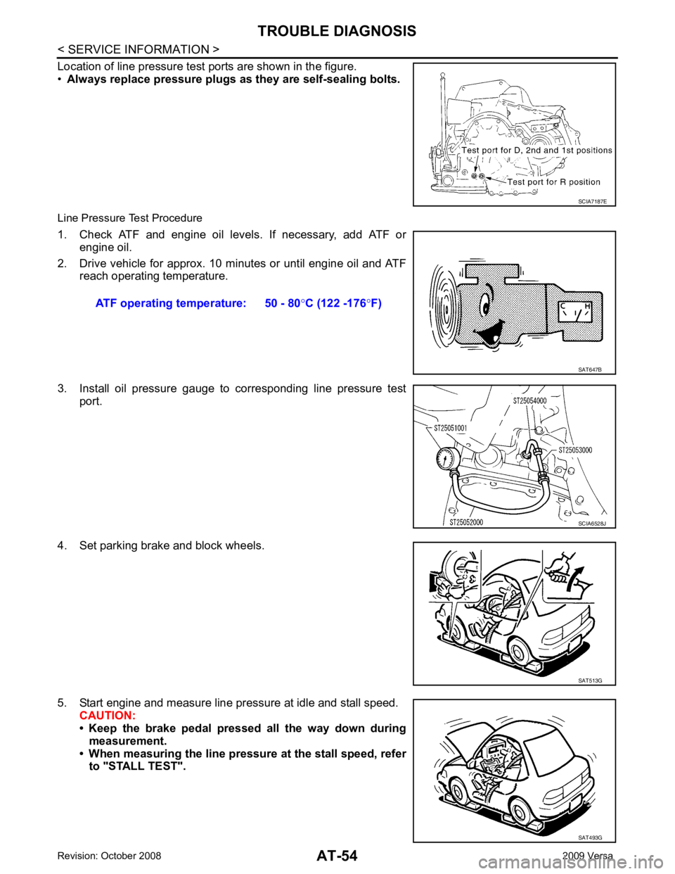
Location of line pressure test ports are shown in the figure.
• Always replace pressure plugs as they are self-sealing bolts.
Line Pressure Test Procedure
1. Check ATF and engine oil levels. If necessary, add ATF or engine oil.
2. Drive vehicle for approx. 10 minutes or until engine oil and ATF reach operating temperature.
3. Install oil pressure gauge to corresponding line pressure test port.
4. Set parking brake and block wheels.
5. Start engine and measure line pressure at idle and stall speed. CAUTION:
• Keep the brake pedal pressed all the way down during
measurement.
• When measuring the line pressure at the stall speed, refer to "STALL TEST". SCIA7187E
ATF operating temperature: 50 - 80
°C (122 -176 °F) SAT647B
SCIA6528J
SAT513G
SAT493G
Page 907 of 4331
CO
NP
O
10. Place the coolant container (with the refill hose inserted)
at the same level as the top of the radiator. Then
open the ball valve on the refill hose so the coolant will be drawn up to fill the cooling system. The cooling
system is full when the vacuum gauge reads zero.
CAUTION:
Do not allow the coolant container to get too low when filling, to avoid air from being drawn into
the cooling system.
11. Remove the Tool from the radiator neck opening.
12. Fill the cooling system reservoir tank to the specif ied level and install the radiator cap. Run the engine to
warm up the cooling system and top up the system as necessary.
FLUSHING COOLING SYSTEM 1. Install reservoir tank if removed. Refer to CO-16, " Component " .
2. Install radiator drain plug. •If water drain plug on cylinder block is removed, close and tighten it. Refer to EM-96, " Disassem-
bly and Assembly " .
CAUTION:
Be sure to clean radiator drain plug and install with new O-ring. Refer to CO-16, " Component " .
3. Fill radiator and reservoir tank with water and reinstall radiator cap.
4. Run engine and warm it up to normal operating temperature.
5. Rev engine two or three times under no-load.
6. Stop engine and wait until it cools down.
7. Drain water from the cooling system.
8. Repeat steps 1 through 7 until clear water begins to drain from radiator.
Page 917 of 4331
CO
NP
O
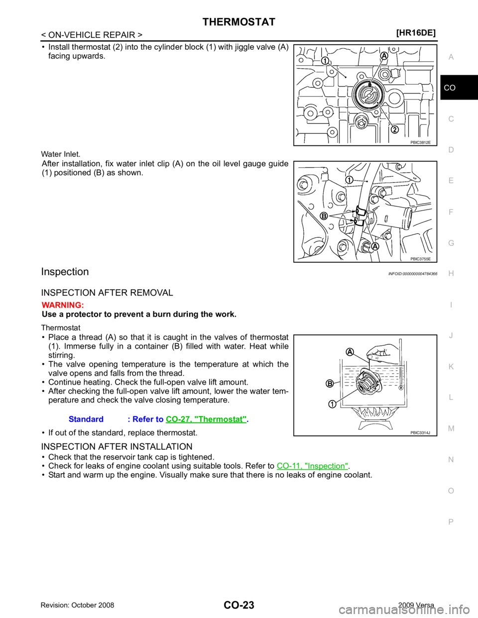
• Install thermostat (2) into the cylinder block (1) with jiggle valve (A)
facing upwards.
Water Inlet. After installation, fix water inlet clip (A) on the oil level gauge guide
(1) positioned (B) as shown.
Inspection INFOID:0000000004784366
INSPECTION AFTER REMOVAL WARNING:
Use a protector to prevent a burn during the work.
Thermostat • Place a thread (A) so that it is caught in the valves of thermostat (1). Immerse fully in a container (B) filled with water. Heat while
stirring.
• The valve opening temperature is the temperature at which the valve opens and falls from the thread.
• Continue heating. Check the full-open valve lift amount.
• After checking the full-open valve lift amount, lower the water tem- perature and check the valve closing temperature.
• If out of the standard, replace thermostat.
INSPECTION AFTER INSTALLATION • Check that the reservoir tank cap is tightened.
• Check for leaks of engine coolant using suitable tools. Refer to CO-11, " Inspection " .
• Start and warm up the engine. Visually make sure that there is no leaks of engine coolant. PBIC3755E
Thermostat " .
Page 931 of 4331
CO
NP
O
10. Place the coolant container (with the refill hose inserted)
at the same level as the top of the radiator. Then
open the ball valve on the refill hose so the coolant will be drawn up to fill the cooling system. The cooling
system is full when the vacuum gauge reads zero.
CAUTION:
Do not allow the coolant container to get too low when filling, to avoid air from being drawn into
the cooling system.
11. Remove the Tool from the radiator neck opening.
12. Fill the cooling system reservoir tank to the specif ied level and install the radiator cap. Run the engine to
warm up the cooling system and top up the system as necessary.
FLUSHING COOLING SYSTEM 1. Install reservoir tank if removed. Refer to CO-38, " Component " .
2. Install radiator drain plug. •If water drain plug on cylinder block is removed, close and tighten it. Refer to EM-200, " Disas-
sembly and Assembly " .
CAUTION:
Be sure to clean radiator drain plug and install with new O-ring. Refer to CO-38, " Component " .
3. Fill radiator and reservoir tank with water and reinstall radiator cap.
4. Run engine and warm it up to normal operating temperature.
5. Rev engine two or three times under no-load.
6. Stop engine and wait until it cools down.
7. Drain water from the cooling system.
8. Repeat steps 1 through 7 until clear water begins to drain from radiator.
Page 961 of 4331
CVT
N
O P
CVT FLUID
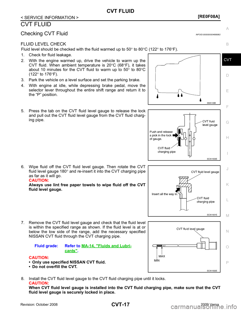
Checking CVT Fluid INFOID:0000000004666862
FLUID LEVEL CHECK Fluid level should be checked with the fluid warmed up to 50 ° to 80 °C (122 ° to 176 °F).
1. Check for fluid leakage.
2. With the engine warmed up, drive the vehicle to warm up the CVT fluid. When ambient temperature is 20 °C (68 °F), it takes
about 10 minutes for the CVT fluid to warm up to 50 ° to 80 °C
(122 ° to 176 °F).
3. Park the vehicle on a level surface and set the parking brake.
4. With engine at idle, while depressing brake pedal, move the selector lever throughout the entire shift range and return it to
the “P” position.
5. Press the tab on the CVT fluid level gauge to release the lock and pull out the CVT fluid level gauge from the CVT fluid charg-
ing pipe.
6. Wipe fluid off the CVT fluid level gauge. Then rotate the CVT fluid level gauge 180 ° and re-insert it into the CVT charging pipe
as far as it will go.
CAUTION:
Always use lint free paper towels to wipe fluid off the CVT
fluid level gauge.
7. Remove the CVT fluid level gauge and check that the fluid level is within the specified range as shown. If the fluid level is at or
below the low side of the range, add the necessary specified
NISSAN CVT fluid through the CVT charging pipe.
CAUTION:
• Only use specified NISSAN CVT fluid.
• Do not overfill the CVT.
8. Install the CVT fluid level gauge to the CVT fluid charging pipe until it locks. CAUTION:
When CVT fluid level gauge is installed into the CVT fluid charging pipe, make sure that the CVT
fluid level gauge is securely locked in place. Fluids and Lubri-
cants " .
Page 987 of 4331
CVT
N
O P
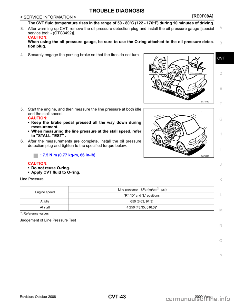
The CVT fluid temperature rises in the range of 50 - 80
°C (122 - 176 °F) during 10 minutes of driving.
3. After warming up CVT, remove the oil pressure detection plug and install the oil pressure gauge [special service tool: - (OTC3492)].
CAUTION:
When using the oil pressure gauge, be sure to use the O-ring attached to the oil pressure detec-
tion plug.
4. Securely engage the parking brake so that the tires do not turn.
5. Start the engine, and then measure the line pressure at both idle and the stall speed.
CAUTION:
• Keep the brake pedal pressed all the way down during
measurement.
• When measuring the line pressure at the stall speed, refer
to "STALL TEST" .
6. After the measurements are complete, install the oil pressure detection plug and tighten to the specified torque below.
CAUTION:
• Do not reuse O-ring.
• Apply CVT fluid to O-ring.
Line Pressure
*: Reference values
Judgement of Line Pressure Test
Page 1140 of 4331
![NISSAN LATIO 2009 Service Repair Manual CVT-196< SERVICE INFORMATION >
[RE0F08B]
CVT FLUID
CVT FLUID
Checking CVT Fluid INFOID:0000000004305570
FLUID LEVEL CHECK
Fluid level should be checked with the fluid warmed up to 50 ° to 80 °C (122 NISSAN LATIO 2009 Service Repair Manual CVT-196< SERVICE INFORMATION >
[RE0F08B]
CVT FLUID
CVT FLUID
Checking CVT Fluid INFOID:0000000004305570
FLUID LEVEL CHECK
Fluid level should be checked with the fluid warmed up to 50 ° to 80 °C (122](/manual-img/5/57359/w960_57359-1139.png)
CVT-196< SERVICE INFORMATION >
[RE0F08B]
CVT FLUID
CVT FLUID
Checking CVT Fluid INFOID:0000000004305570
FLUID LEVEL CHECK
Fluid level should be checked with the fluid warmed up to 50 ° to 80 °C (122 ° to 176 °F).
1. Check for fluid leakage.
2. With the engine warmed up, drive the vehicle to warm up the CVT fluid. When ambient temperature is 20 °C (68 °F), it takes
about 10 minutes for the CVT fluid to warm up to 50 ° to 80 °C
(122 ° to 176 °F).
3. Park the vehicle on a level surface and set the parking brake.
4. With engine at idle, while depressing brake pedal, move the selector lever throughout the entire shift range and return it to
the “P” position.
5. Press the tab on the CVT fluid level gauge to release the lock and pull out the CVT fluid level gauge from the CVT fluid charg-
ing pipe.
6. Wipe fluid off the CVT fluid level gauge. Then rotate the CVT fluid level gauge 180 ° and re-insert it into the CVT charging pipe
as far as it will go.
CAUTION:
Always use lint free paper towels to wipe fluid off the CVT
fluid level gauge.
7. Remove the CVT fluid level gauge and check that the fluid level is within the specified range as shown. If the fluid level is at or
below the low side of the range, add the necessary specified
NISSAN CVT fluid through the CVT charging pipe.
CAUTION:
• Only use specified NISSAN CVT fluid.
• Do not overfill the CVT.
8. Install the CVT fluid level gauge to the CVT fluid charging pipe until it locks. CAUTION:
When CVT fluid level gauge is in stalled into the CVT fluid charging pipe, make sure that the CVT
fluid level gauge is securely locked in place. SMA146B
SCIA1933E
SCIA1931E
Fluid grade: Refer to
MA-14, " Fluids and Lubri-
cants " .
SCIA1932E