2009 NISSAN LATIO change time
[x] Cancel search: change timePage 116 of 4331
AT
N
O P
5. Accelerate vehicle to 20 to 25 km/h (12 to 16 MPH) under the following conditions and release the accel-
erator pedal completely.
THROTTLE POSI: Less th an 1.0/8 (at all times during step 4)
SLCT LVR POSI: “D” position
- Make sure that “GEAR” shows “2” after releasing pedal.
6. Depress accelerator pedal to WOT (more than 7.0/ 8 of “THROTTLE POSI”) quickly from a speed of 20 to
25 km/h (12 to 16 MPH) until “TESTING” changes to “STOP VEHICLE” or “COMPLETED”. (It will take
approximately 3 seconds.)
If the check result NG appears on CONSULT-III screen, go to AT-111, " Diagnosis Procedure " .
If “STOP VEHICLE” appears on CONSULT-III screen, go to the following step.
- Make sure that “GEAR” shows “1” when depressing accelerator pedal to WOT.
- If “TESTING” does not appear on CONSULT-III fo r a long time, select “SELF-DIAG RESULTS” for
“TRANSMISSION”. In case a DTC other than “P0731 A/T 1ST GR FNCTN” is shown, refer to AT-79," CONSULT-III Function (TRANSMISSION) " .
7. Stop vehicle.
8. Follow the instruction displayed. (Check for normal shifting referring to the table below.)
9. Make sure that “OK” is disp layed. (If “NG” is displayed, refer to “Diagnostic Procedure”.)
Refer to AT-111, " Diagnosis Procedure " .
Refer to AT-64, " Vehicle Speed at Which Gear Shifting Occurs " .
WITH GST
Follow the procedure “WITH CONSULT-III”.
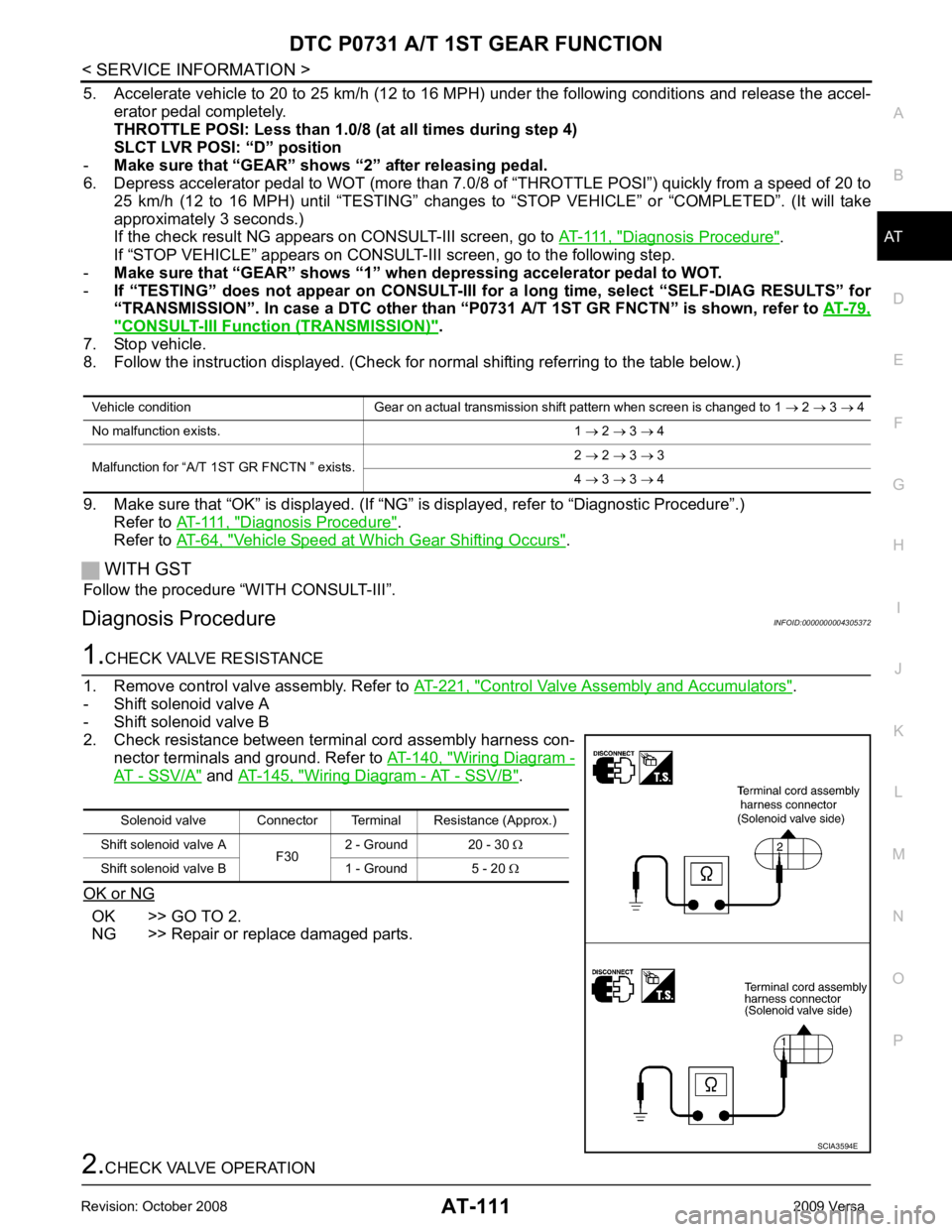
Diagnosis Procedure INFOID:0000000004305372Control Valve Assembly and Accumulators " .
- Shift solenoid valve A
- Shift solenoid valve B
2. Check resistance between terminal cord assembly harness con- nector terminals and ground. Refer to AT-140, " Wiring Diagram -
AT - SSV/A " and
AT-145, " Wiring Diagram - AT - SSV/B " .
OK or NG OK >> GO TO 2.
NG >> Repair or replace damaged parts. Solenoid valve Connector Terminal Resistance (Approx.)
Shift solenoid valve A F302 - Ground 20 - 30
Ω
Shift solenoid valve B 1 - Ground 5 - 20 Ω
Page 119 of 4331
Diagnosis Procedure " .
If “STOP VEHICLE” appears on CONSUL T-III screen, go to following step.
- Make sure that “GEAR” shows “2” wh en depressing accelerator pedal to WOT.
- If “TESTING” does not appear on CONSULT-III fo r a long time, select “SELF-DIAG RESULTS” for
“TRANSMISSION”. In case a DTC other than “P0732 A/T 2ND GR FNCTN” is shown, refer to AT-79," CONSULT-III Function (TRANSMISSION) " .
7. Stop vehicle.
8. Follow the instruction displayed. (Check for normal shifting referring to the table below.)
9. Make sure that “OK” is displayed. (If “NG” is displayed, refer to “Diagnostic Procedure”.)
Refer to AT-114, " Diagnosis Procedure " .
Refer to AT-64, " Vehicle Speed at Which Gear Shifting Occurs " .
WITH GST
Follow the procedure “WITH CONSULT-III”.
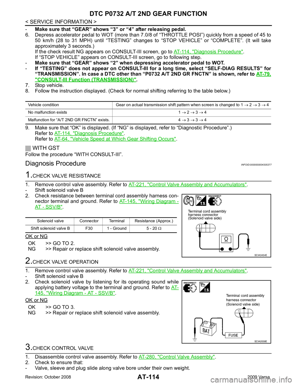
Diagnosis Procedure INFOID:0000000004305377Control Valve Assembly and Accumulators " .
- Shift solenoid valve B
2. Check resistance between terminal cord assembly harness con- nector terminal and ground. Refer to AT-145, " Wiring Diagram -
AT - SSV/B " .
OK or NG OK >> GO TO 2.
NG >> Repair or replace shift solenoid valve assembly. Control Valve Assembly and Accumulators " .
- Shift solenoid valve B
2. Check solenoid valve by listening for its operating sound while applying battery voltage to the terminal and ground. Refer to AT-145, " Wiring Diagram - AT - SSV/B " .
OK or NG OK >> GO TO 3.
NG >> Repair or replace shift solenoid valve assembly. Control Valve Assembly " .
2. Check to ensure that:
- Valve, sleeve and plug slide along valve bore under their own weight. Vehicle condition Gear on actual transmission shift pattern when screen is changed to 1
→ 2 → 3 → 4
No malfunction exists 1 → 2 → 3 → 4
Malfunction for “A/T 2ND GR FNCTN” exists. 4 → 3 → 3 → 4 Solenoid valve Connector Terminal Resistance (Approx.)
Shift solenoid valve B F30 1 - Ground 5 - 20 Ω SCIA2058E
Page 122 of 4331
DTC P0733 A/T 3RD GEAR FUNCTION
AT-117
< SERVICE INFORMATION >
D
E
F
G H
I
J
K L
M A
B AT
N
O P
-
Make sure that “GEAR” shows “4” after releasing pedal.
6. Depress accelerator pedal steadily with 3.5/8 - 4.5/ 8 of “THROTTLE POSI” from a speed of 60 to 75 km/h
(37 to 47 MPH) until “TESTING” changes to “STOP VE HICLE” or “COMPLETED”. (It will take approxi-
mately 3 seconds.)
If the check result NG appears on CONSULT-III screen, go to AT-117, " Diagnosis Procedure " .
If “STOP VEHICLE” appears on CONSULT-III screen, go to following step.
- Make sure that “GEAR” shows “3” when depr essing accelerator pedal with 3.5/8 - 4.5/8 of
“THROTTLE POSI”.
- If “TESTING” does not appear on CONSULT-III fo r a long time, select “SELF-DIAG RESULTS” for
“TRANSMISSION”. In case a DTC ot her than “P0733 A/T 3RD GR FNCTN” is shown, refer to AT-79," CONSULT-III Function (TRANSMISSION) " .
7. Stop vehicle.
8. Follow the instruction displayed. (Check for normal shifting referring to the table below.)
9. Make sure that “OK” is disp layed. (If “NG” is displayed, refer to “Diagnostic Procedure”.)
Refer to AT-117, " Diagnosis Procedure " .
Refer to AT-64, " Vehicle Speed at Which Gear Shifting Occurs " .
WITH GST
Follow the procedure “WITH CONSULT-III”.
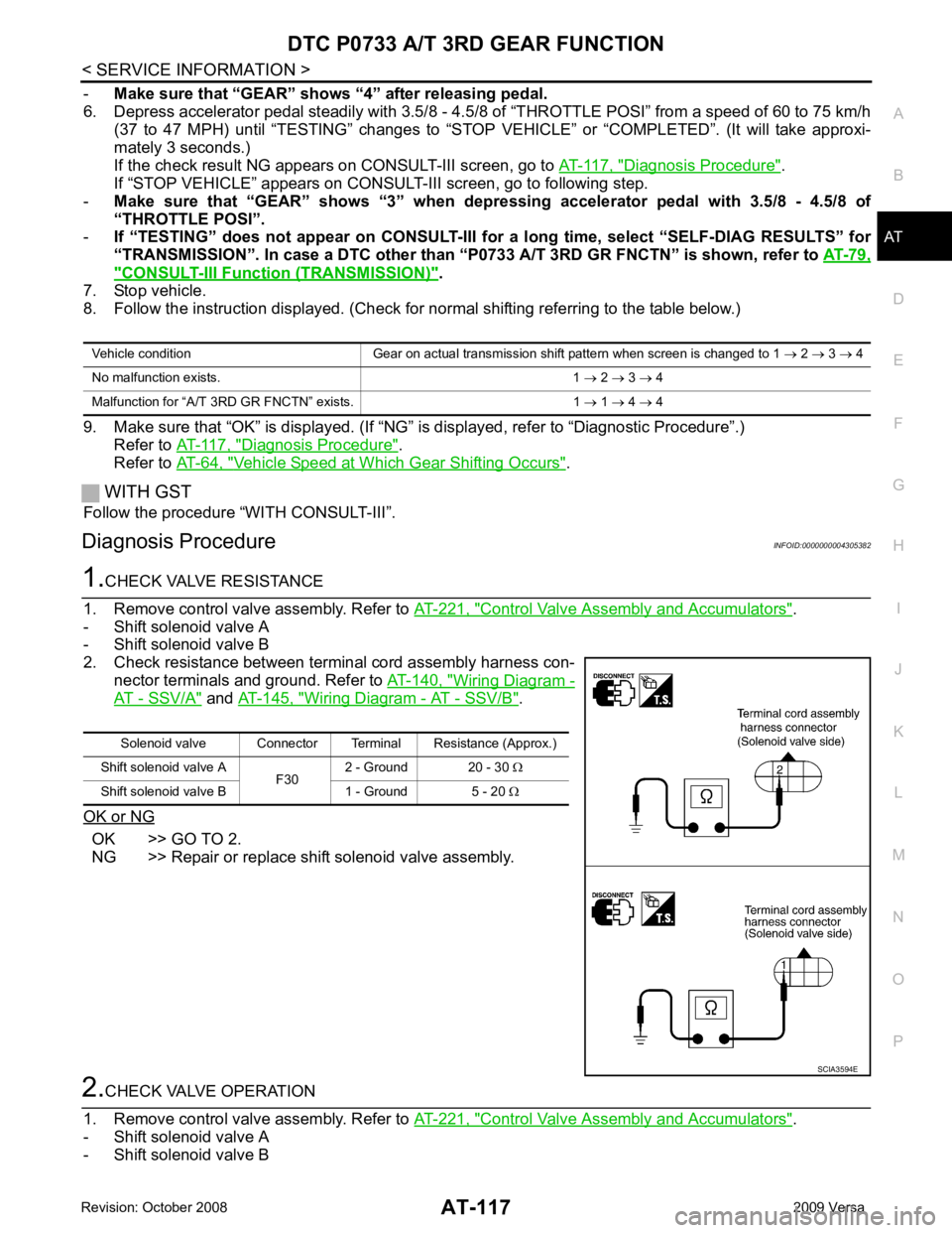
Diagnosis Procedure INFOID:00000000043053821.
CHECK VALVE RESISTANCE
1. Remove control valve assembly. Refer to AT-221, " Control Valve Assembly and Accumulators " .
- Shift solenoid valve A
- Shift solenoid valve B
2. Check resistance between terminal cord assembly harness con- nector terminals and ground. Refer to AT-140, " Wiring Diagram -
AT - SSV/A " and
AT-145, " Wiring Diagram - AT - SSV/B " .
OK or NG OK >> GO TO 2.
NG >> Repair or replace shift solenoid valve assembly. 2.
CHECK VALVE OPERATION
1. Remove control valve assembly. Refer to AT-221, " Control Valve Assembly and Accumulators " .
- Shift solenoid valve A
- Shift solenoid valve B Vehicle condition Gear on actual transmission shift pattern when screen is changed to 1
→ 2 → 3 → 4
No malfunction exists. 1 → 2 → 3 → 4
Malfunction for “A/T 3 RD GR FNCTN” exists. 1 → 1 → 4 → 4 Solenoid valve Connector Terminal Resistance (Approx.)
Shift solenoid valve A F302 - Ground 20 - 30
Ω
Shift solenoid valve B 1 - Ground 5 - 20 Ω SCIA3594E
Page 389 of 4331

AV
N
O P
• to audio unit terminal 21 (with premium system)
• through body grounds M57 and M61 and
• to subwoofer terminal 3 (with premium system)
• through body grounds B7 and B19.
Then audio signals are supplied
• through audio unit terminals 2, 3, 4, 5, 11, 12, 13, and 14
• to terminals + and - of front door speaker LH and RH and
• to terminals + and - of tweeter LH and RH and
• to terminals + and - of rear door speaker LH and RH and
• to terminals 2 and 6 of subwoofer (with premium system).
Steering Wheel Audio Contro l Switches (with Bluetooth)
When one of steering wheel audio control switches is pus hed, the resistance in steering switch circuit changes
depending on which button is pushed.
Satellite Radio Tuner (Pre-wiring) The satellite radio tuner pre-wiring allows connection of a satellite radio tuner.
Power is supplied at all times
• through 20A fuse (No. 27, located in the fuse and fusible link box)
• to satellite radio tuner pre-wiring terminal 32.
With the ignition switch in the ACC or ON position, power is supplied
• through 10A fuse (No. 20, located in the fuse and fusible link box)
• to satellite radio tuner pre-wiring terminal 36.
Then audio signals are supplied
• through satellite radio tuner pre-wiring terminals 21, 22, 23 and 24
• to audio unit terminals 41, 42, 43 and 44.
Satellite Radio Tuner (Factory Installed)
Power is supplied at all times
• through 20A fuse (No. 27, located in the fuse and fusible link box)
• to satellite radio tuner terminal 32.
With the ignition switch in the ACC or ON position, power is supplied
• through 10A fuse (No. 20, located in the fuse and fusible link box)
• to satellite radio tuner terminal 36.
Ground is supplied through the case of the satellite radio tuner.
Then audio signals are supplied
• through satellite radio tuner terminals 21, 22, 23 and 24
• to audio unit terminals 41, 42, 43 and 44.
Ground is supplied through the case of the satellite radio tuner.
SPEED SENSITIVE VOLUME SYSTEM (MID LEVEL AND PREMIUM SYSTEM) Volume level of this system goes up and down automatica lly in proportion to the vehicle speed. The control
level can be selected by the customer. Refer to Owner's Manual for operating instructions.
Page 406 of 4331
35, " Sound Is Not Heard from S
ubwoofer (Premium System) " .
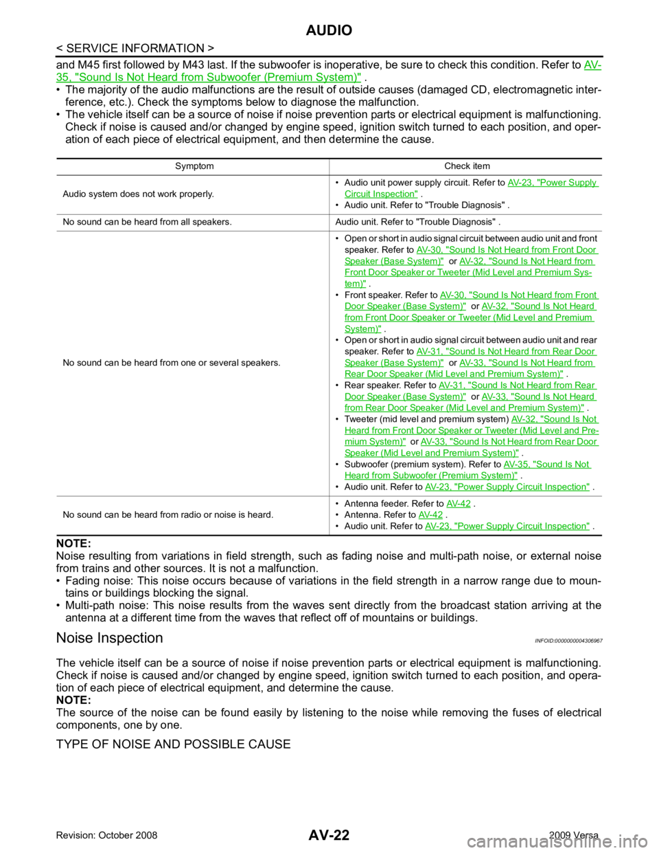
• The majority of the audio malfunctions are the result of outside causes (damaged CD, electromagnetic inter-
ference, etc.). Check the symptom s below to diagnose the malfunction.
• The vehicle itself can be a source of noise if noise prevention parts or electrical equipment is malfunctioning.
Check if noise is caused and/or changed by engine speed, ignition switch turned to each position, and oper-
ation of each piece of electrical equipment, and then determine the cause.
NOTE:
Noise resulting from variations in field strength, such as fading noise and multi-path noise, or external noise
from trains and other sources. It is not a malfunction.
• Fading noise: This noise occurs because of variations in the field strength in a narrow range due to moun- tains or buildings blocking the signal.
• Multi-path noise: This noise results from the waves s ent directly from the broadcast station arriving at the
antenna at a different time from the waves that reflect off of mountains or buildings.
Noise Inspection INFOID:0000000004306967
The vehicle itself can be a source of noise if noise prevention parts or electrical equipment is malfunctioning.
Check if noise is caused and/or changed by engine speed, ignition switch turned to each position, and opera-
tion of each piece of electrical equipment, and determine the cause.
NOTE:
The source of the noise can be found easily by listening to the noise while removing the fuses of electrical
components, one by one.
TYPE OF NOISE AND POSSIBLE CAUSE Symptom Check item
Audio system does not work properly. • Audio unit power supply circuit. Refer to
AV-23, " Power Supply
Circuit Inspection " .
• Audio unit. Refer to "Trouble Diagnosis" .
No sound can be heard from all speakers. Audio unit. Refer to "Trouble Diagnosis" .
No sound can be heard from one or several speakers. • Open or short in audio signal circuit between audio unit and front
speaker. Refer to AV-30, " Sound Is Not Heard from Front Door
Speaker (Base System) " or
AV-32, " Sound Is Not Heard from
Front Door Speaker or Tweeter (Mid Level and Premium Sys-
tem) " .
• Front speaker. Refer to AV-30, " Sound Is Not Heard from Front
Door Speaker (Base System) " or
AV-32, " Sound Is Not Heard
from Front Door Speaker or Tweeter (Mid Level and Premium
System) " .
• Open or short in audio signal circuit between audio unit and rear
speaker. Refer to AV-31, " Sound Is Not Heard from Rear Door
Speaker (Base System) " or
AV-33, " Sound Is Not Heard from
Rear Door Speaker (Mid Level and Premium System) " .
• Rear speaker. Refer to AV-31, " Sound Is Not Heard from Rear
Door Speaker (Base System) " or
AV-33, " Sound Is Not Heard
from Rear Door Speaker (Mid Level and Premium System) " .
• Tweeter (mid level and premium system) AV-32, " Sound Is Not
Heard from Front Door Speaker or Tweeter (Mid Level and Pre-
mium System) " or
AV-33, " Sound Is Not Heard from Rear Door
Speaker (Mid Level and Premium System) " .
• Subwoofer (premium system). Refer to AV-35, " Sound Is Not
Heard from Subwoofer (Premium System) " .
• Audio unit. Refer to AV-23, " Power Supply Circuit Inspection " .
No sound can be heard from radio or noise is heard. • Antenna feeder. Refer to
AV-42 .
• Antenna. Refer to AV-42 .
• Audio unit. Refer to AV-23, " Power Supply Circuit Inspection " .
Page 429 of 4331
AV
N
O P
tooth cellular telephones may not be recognized by t
he Bluetooth control unit. When a cellular telephone or
the Bluetooth control unit is replaced, the telephone must be paired with the Bluetooth control unit. Different
cellular telephones may have different pairing procedures. Refer to the cellular telephone operating manual.
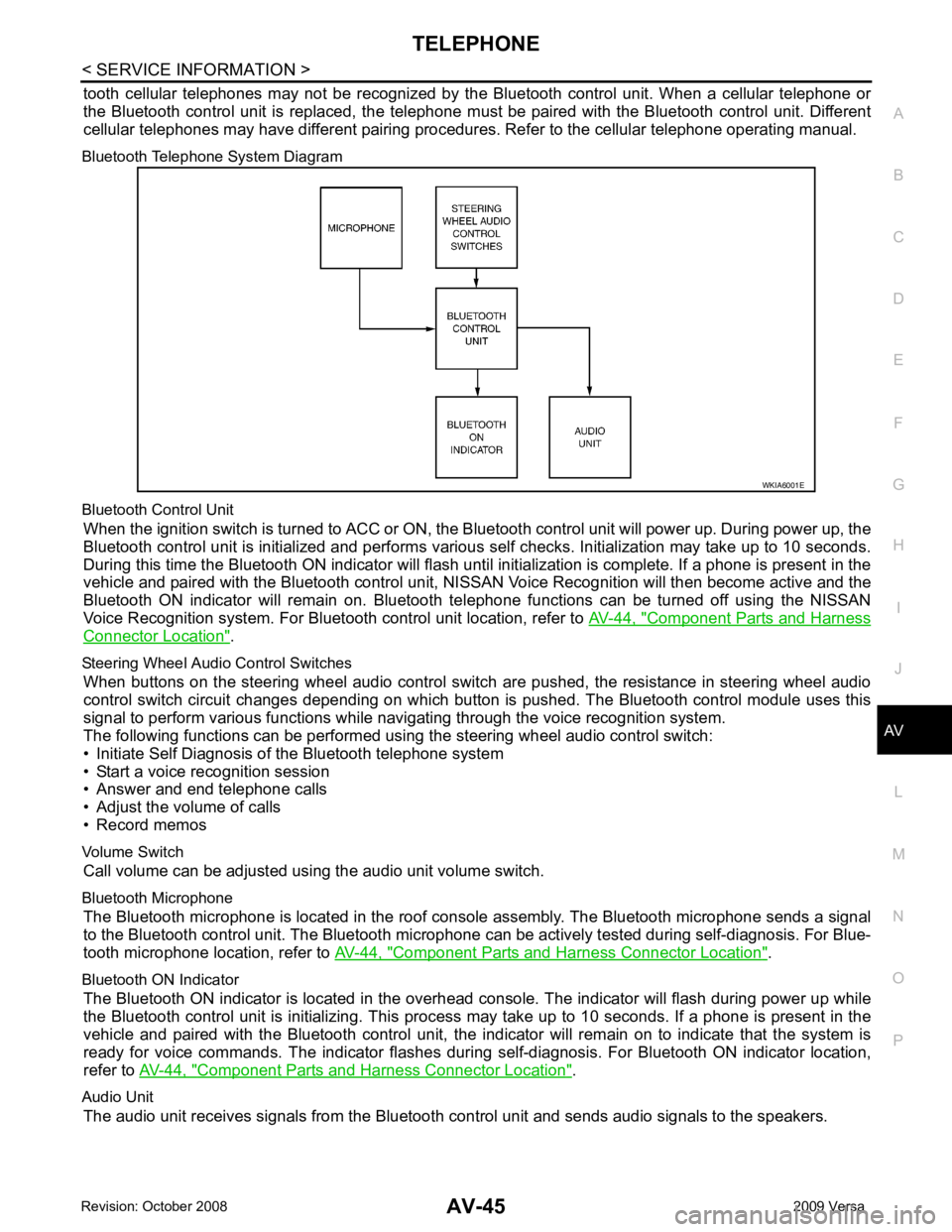
Bluetooth Telephone System Diagram
Bluetooth Control Unit When the ignition switch is turned to ACC or ON, the Bluetooth control unit will power up. During power up, the
Bluetooth control unit is initialized and performs various self checks. Initialization may take up to 10 seconds.
During this time the Bluetooth ON indicator will flash until initialization is complete. If a phone is present in the
vehicle and paired with the Bluetooth control unit, NIS SAN Voice Recognition will then become active and the
Bluetooth ON indicator will remain on. Bluetooth te lephone functions can be turned off using the NISSAN
Voice Recognition system. For Bluetooth control unit location, refer to AV-44, " Component Parts and Harness
Connector Location " .
Steering Wheel Audio Control Switches When buttons on the steering wheel audio control switch are pushed, the resistance in steering wheel audio
control switch circuit changes depending on which button is pushed. The Bluetooth control module uses this
signal to perform various functions while navigating through the voice recognition system.
The following functions can be performed usi ng the steering wheel audio control switch:
• Initiate Self Diagnosis of the Bluetooth telephone system
• Start a voice recognition session
• Answer and end telephone calls
• Adjust the volume of calls
• Record memos
Volume Switch Call volume can be adjusted using the audio unit volume switch.
Bluetooth Microphone The Bluetooth microphone is located in the roof c onsole assembly. The Bluetooth microphone sends a signal
to the Bluetooth control unit. The Bluetooth microphone can be actively tested during self-diagnosis. For Blue-
tooth microphone location, refer to AV-44, " Component Parts and Harness Connector Location " .
Bluetooth ON Indicator The Bluetooth ON indicator is located in the overhead console. The indicator will flash during power up while
the Bluetooth control unit is initializing. This process may take up to 10 seconds. If a phone is present in the
vehicle and paired with the Bluetooth control unit, the indi cator will remain on to indicate that the system is
ready for voice commands. The indicator flashes duri ng self-diagnosis. For Bluetooth ON indicator location,
refer to AV-44, " Component Parts and Harness Connector Location " .
Audio Unit The audio unit receives signals from the Bluetooth control unit and sends audio signals to the speakers.
Page 445 of 4331
BCS
N
O P
BCM (BODY CONTROL MODULE)
System Description INFOID:0000000004306833
BCM (body control module) controls the operation of various electrical units installed on the vehicle.
BCM FUNCTION BCM has a combination switch reading function for reading the operation of combination switches (light, wiper,
washer, turn signal) in addition to the function for c ontrolling the operation of various electrical components.
Also, it functions as an interface that receives signal s from the front air control, and sends signals to ECM
using CAN communication.
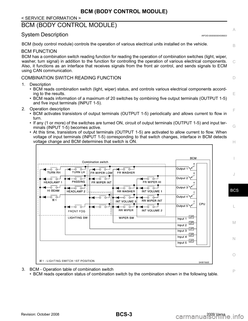
COMBINATION SWITCH READING FUNCTION 1. Description • BCM reads combination switch (light, wiper) status , and controls various electrical components accord-
ing to the results.
• BCM reads information of a maximum of 20 switches by combining five output terminals (OUTPUT 1-5)
and five input terminals (INPUT 1-5).
2. Operation description • BCM activates transistors of output terminals (OUTPUT 1-5) periodically and allows current to flow in
turn.
• If any (1 or more) of the switches are turned ON, circuit of output terminals (OUTPUT 1-5) and input ter-
minals (INPUT 1-5) becomes active.
• At this time, transistors of output terminals (OUTPUT 1-5) are activated to allow current to flow. When
voltage of input terminals (INPUT 1-5) corresponding to that switch changes, interface in BCM detects
voltage change and BCM determines that switch is ON.
3. BCM - Operation table of combination switch • BCM reads operation status of combination switch by the combination shown in the following table.
Page 530 of 4331
BL
N
O P
1: With Intelligent Key
2: Without Intelligent Key
3: Hatchback without Intelligent Key
4: Sedan without Intelligent Key
5: Hatchback
6: Sedan
7: With power door locks
8: With power windows
How to Perform Trouble Diagnosis INFOID:0000000004305012
1. Confirm the symptom or customer complaint.
2. Understand operation, description and function description. Refer to BL-58, " System Description " .
3. Perform the Preliminary Check. Refer to LT-11, " Preliminary Check " .
4. Check symptom and repair or replace the component.
5. Does the remote keyless entry system operate normally? If YES, GO TO 6. If NO, GO TO 4.
6. Inspection End.
Preliminary Check INFOID:0000000004305013
CHECK BCM CONFIGURATION Configuration " .
OK or NG OK >> Refer to
BL-71, " Work Flow " .
NG >> Change BCM configuration for "KEYLESS ENTRY" to "WITH". Refer to BCS-18, " Configuration " .
CONSULT-III Function (BCM) INFOID:0000000004305014
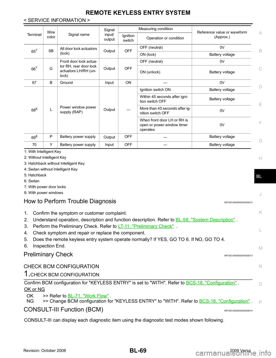
CONSULT-III can display each diagnostic item using the diagnostic test modes shown following. 65
7
SBAll door lock actuators
(lock) Output OFFOFF (neutral) 0V
ON (lock) Battery voltage
66 7
GFront door lock actua-
tor RH, rear door lock
actuators LH/RH (un-
lock) Output OFFOFF (neutral) 0V
ON (unlock) Battery voltage
67 B Ground Input ON — 0V
68 8
LPower window power
supply (RAP) Output —Ignition switch ON Battery voltage
Within 45 seconds after igni-
tion switch OFF Battery voltage
More than 45 seconds after ig-
nition switch OFF 0V
When front door LH or RH is
open or power window timer
operates 0V
69 8
P Battery power supply
OutputOFF
— Battery voltage
70 Y Battery power supply Input OFF — Battery voltage
Terminal
Wire
color Signal name Signal
input/
output Measuring condition
Reference value or waveform
(Approx.)
Ignition
switch Operation or condition