2009 NISSAN LATIO trunk
[x] Cancel search: trunkPage 423 of 4331
AV
N
O P
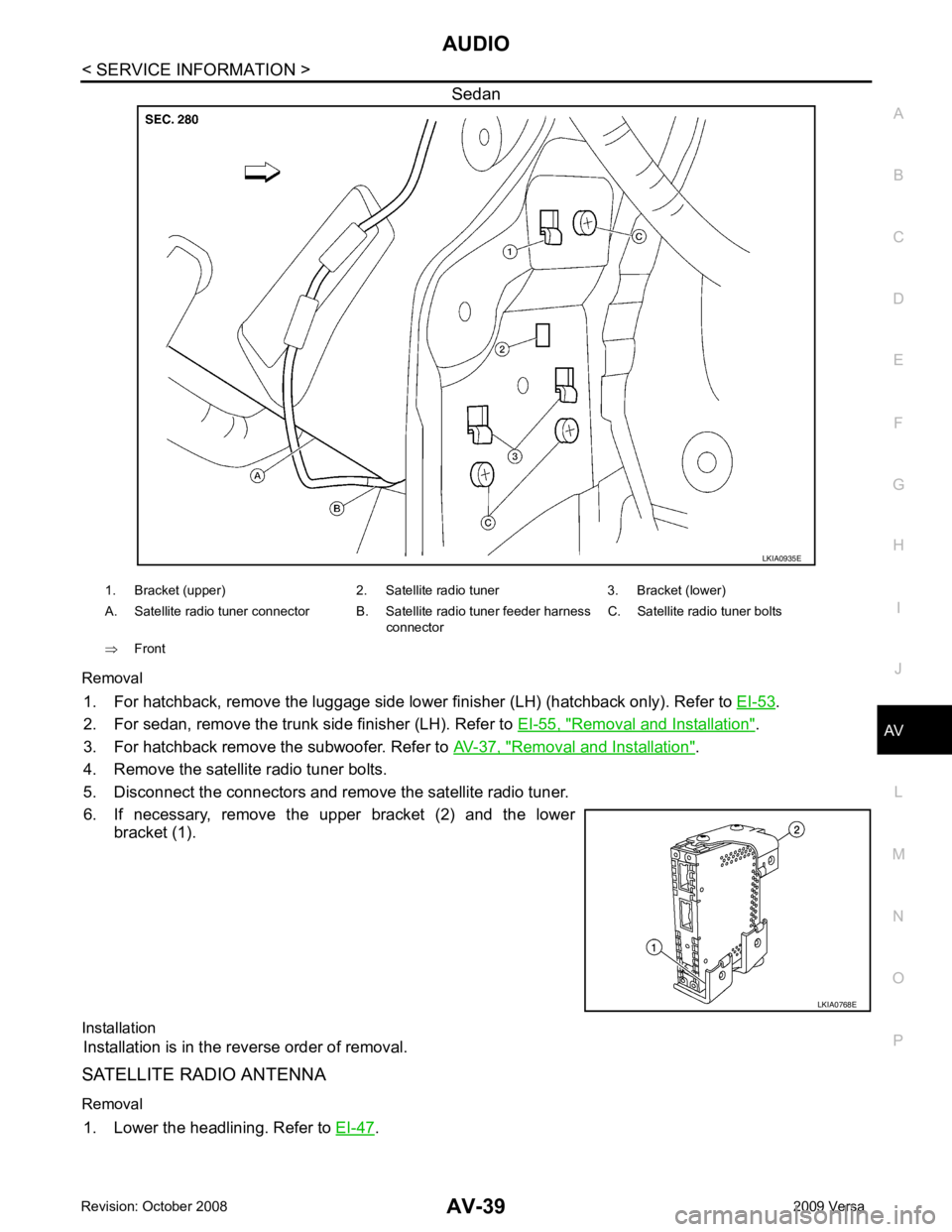
Sedan
Removal 1. For hatchback, remove the luggage side lower finisher (LH) (hatchback only). Refer to EI-53 .
2. For sedan, remove the trunk side finisher (LH). Refer to EI-55, " Removal and Installation " .
3. For hatchback remove the subwoofer. Refer to AV-37, " Removal and Installation " .
4. Remove the satellite radio tuner bolts.
5. Disconnect the connectors and remove the satellite radio tuner.
6. If necessary, remove the upper bracket (2) and the lower bracket (1).
Installation Installation is in the reverse order of removal.
SATELLITE RADIO ANTENNA
Removal 1. Lower the headlining. Refer to EI-47 .
Page 441 of 4331
AV
N
O P
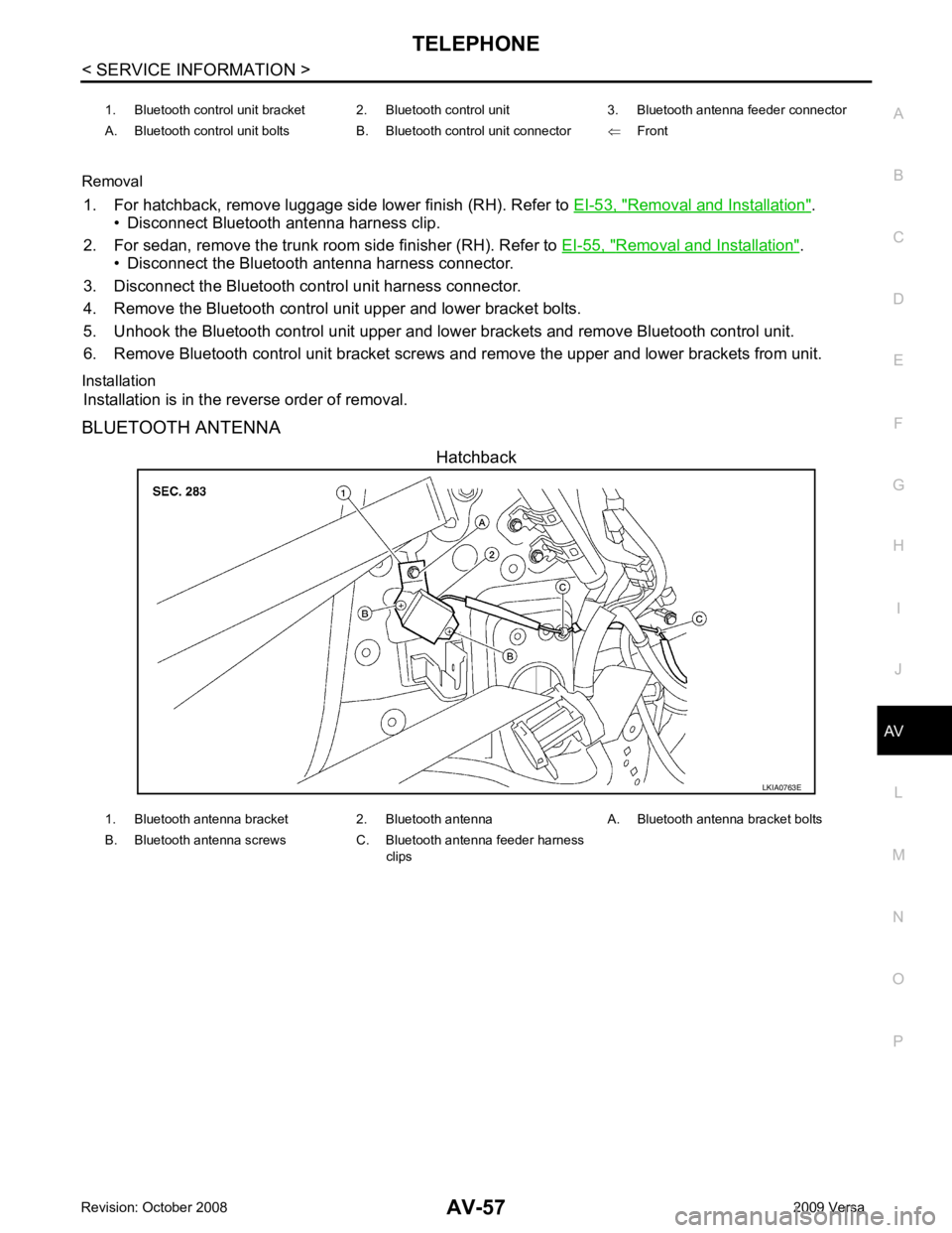
Removal
1. For hatchback, remove luggage side lower finish (RH). Refer to EI-53, " Removal and Installation " .
• Disconnect Bluetooth antenna harness clip.
2. For sedan, remove the trunk room side finisher (RH). Refer to EI-55, " Removal and Installation " .
• Disconnect the Bluetooth antenna harness connector.
3. Disconnect the Bluetooth control unit harness connector.
4. Remove the Bluetooth control unit upper and lower bracket bolts.
5. Unhook the Bluetooth control unit upper and lowe r brackets and remove Bluetooth control unit.
6. Remove Bluetooth control unit bracket screws and remove the upper and lower brackets from unit.
Installation Installation is in the reverse order of removal.
BLUETOOTH ANTENNA
Hatchback
1. Bluetooth control unit bracket 2. Bluetooth control unit 3. Bluetooth antenna feeder connector
A. Bluetooth control unit bolts B. Bluetooth control unit connector ⇐Front
Page 449 of 4331

BCS
N
O P
CAN Communication System Description INFOID:0000000004306834
Refer to LAN-8, " System Description " .
Panic alarm
• Key switch
• Keyfob IPDM E/R
Vehicle security system • All door switches
• Keyfob
• Door lock/unlock switch
• Trunk key cylinder switch (Se-
dan)
• Front door key cylinder switch LH • IPDM/ER
• Security indicator lamp
Battery saver control • Ignition switch
• Combination switch IPDM E/R
Headlamp Combination switch IPDM E/R
Tail lamp Combination switch IPDM E/R
Front fog lamp (with front fog lamps) Combination switch IPDM E/R
Turn signal lamp Combination switch • Turn signal lamp
• Combination meter
Hazard lamp Hazard switch • Turn signal lamp
• Combination meter
Room lamp timer • Key switch
• Keyfob
• Main power window and door lock/unlock switch
• Front door switch LH
• All door switch Interior room lamp
Back door switch signal (Hatchback) Back door lock assembly Luggage room lamp
Back door lock signal (Hatchback) Back door lock assembly Back door opener
Trunk lamp switch signal (Sedan) Trunk lamp switch and trunk re-
lease solenoid Luggage room lamp
Trunk lid opener signal (Sedan) Trunk lamp switch and trunk re-
lease solenoid Trunk lid opener
Key warning chime • Key switch
• Front door switch LH Combination meter (warning buzzer)
Light warning chime • Combination switch
• Key switch
• Front door switch LH Combination meter (warning buzzer)
Seat belt warning chime • Seat belt buckle switch LH
• Ignition switch Combination meter (warning buzzer)
Front wiper and washer system • Combination switch
• Ignition switch IPDM E/R
Rear window defogger Rear window defogger switch IPDM E/R
Rear wiper and washer system
(Hatchback) • Combination switch
• Ignition switch Rear wiper motor
A/C switch signal Front air control ECM
Blower fan switch signal Front air control ECM
A/C indicator signal Front air control A/C indicator
Low tire pressure warning system Remote keyless entry receiver Combination meter System Input Output
Page 455 of 4331
BCM (BODY CONTROL MODULE)
BCS-13
< SERVICE INFORMATION >
C
D E
F
G H
I
J
L
M A
B BCS
N
O P
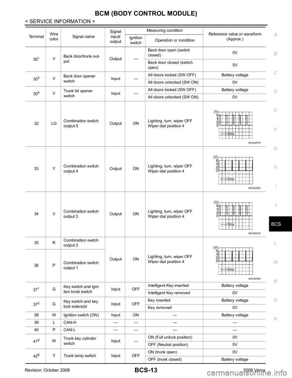
30
1
VBack door/trunk out-
put Output —Back door open (switch
closed) 0V
Back door closed (switch
open) 5V
30 3
VBack door opener
switch Input —All doors locked (SW OFF) Battery voltage
All doors unlocked (SW ON) 0V
30 4
VTrunk lid opener
switch Input —All doors locked (SW OFF) Battery voltage
All doors unlocked (SW ON) 0V
32 LG Combination switch
output 5 Output ONLighting, turn, wiper OFF
Wiper dial position 4
33 Y Combination switch
output 4 Output ON
Lighting, turn, wiper OFF
Wiper dial position 4
34 V Combination switch
output 3 Output ONLighting, turn, wiper OFF
Wiper dial position 4
35 R Combination switch
output 2
Output ONLighting, turn, wiper OFF
Wiper dial position 4
36 P Combination switch
output 1
37 1
GKey switch and igni-
tion knob switch Input OFFIntelligent Key inserted Battery voltage
Intelligent Key removed 0V
37 2
GKey switch and key
lock solenoid Input OFFKey inserted Battery voltage
Key removed 0V
38 W Ignition switch (ON) Input ON — Battery voltage
39 L CAN-H — — — —
40 P CAN-L — — — —
41 6
WTrunk key cylinder
switch Input —ON (Full unlock position) 0V
OFF (Neutral position) 5V
42 6
Y Trunk lamp switch Input OFF ON (trunk open) 0V
OFF (trunk closed) Battery voltage
Terminal
Wire
color Signal name Signal
input/
output Measuring condition
Reference value or waveform
(Approx.)
Ignition
switch Operation or condition SKIA5291E
SKIA5292E
SKIA5291E
SKIA5292E
Page 464 of 4331

BL
N
O P
Check Trunk Lid Opener S
witch Circuit (With Intel-
ligent Key) ........................................................... ..
212
Check Trunk Release Solenoid Circuit ............... ..214
FUEL FILLER LID OPENER .......................... ..217
Removal and Installation of Fuel Filler Lid Opener ..217
VEHICLE SECURITY (THEFT WARNING)
SYSTEM ......................................................... ..
218
Component Parts and Harness Connector Loca-
tion ...................................................................... ..
218
System Description ............................................. ..219
CAN Communication System Description ........... ..221
Schematic ........................................................... ..222
Wiring Diagram - VEHSEC - ............................... ..223
Terminal and Reference Value for BCM ............. ..227
Terminal and Re ference Value for Intelligent Key
Unit ...................................................................... ..
231
CONSULT-III Function (BCM) ............................. ..233
Trouble Diagnosis ............................................... ..235
Preliminary Check ............................................... ..235
Symptom Chart ................................................... ..237
Diagnosis Procedure 1 ........................................ ..238
Diagnosis Procedure 2 ........................................ ..241
Diagnosis Procedure 3 ........................................ ..242
Diagnosis Procedure 4 ........................................ ..242
Diagnosis Procedure 5 ........................................ ..242
Diagnosis Procedure 6 ........................................ ..242
Diagnosis Procedure 7 ........................................ ..242
Diagnosis Procedure 8 ........................................ ..244
Diagnosis Procedure 9 ........................................ ..245 NATS (Nissan Anti-Theft System) ................
248
Component Parts and Harness Connector Loca-
tion ....................................................................... ..
248
System Description .............................................. ..248
System Composition ............................................ ..249
ECM Re-communicating Function ....................... ..249
Wiring Diagram - NATS - ..................................... ..251
Terminal and Reference Value for BCM ................252
CONSULT-III Function ........................................ ..256
Trouble Diagnosis Procedure .............................. ..257
Trouble Diagnosis ................................................ ..259
Diagnosis Procedure 1 ........................................ ..260
Diagnosis Procedure 2 ........................................ ..262
Diagnosis Procedure 3 ........................................ ..263
Diagnosis Procedure 4 ........................................ ..264
Diagnosis Procedure 5 ........................................ ..265
Diagnosis Procedure 6 ........................................ ..266
How to Replace NATS Antenna Amp .................. ..266
BODY REPAIR ................................................ 267
Body Exterior Paint Color .................................... ..267
Body Component Parts ....................................... ..269
Corrosion Protection ............................................ ..274
Body Sealing ....................................................... ..278
Body Construction ............................................... ..284
Body Alignment ................................................... ..286
Handling Precaution for Plastics .......................... ..303
Precaution in Repairing High Strength Steel ....... ..307
Foam Repair ........................................................ ..310
Replacement Operation ....................................... ..313
Page 470 of 4331
BL
N
O P
SILICONE GREASE
Used instead of UHMW tape that will be visible or not fit.
Note: Will only last a few months.
SILICONE SPRAY
Use when grease cannot be applied.
DUCT TAPE
Use to eliminate movement.
CONFIRM THE REPAIR Confirm that the cause of a noise is repaired by test driving the vehicle. Operate the vehicle under the same
conditions as when the noise originally occurred. Refer to the notes on the Diagnostic Worksheet.
Generic Squeak and Rattle Troubleshooting INFOID:0000000004304978
Refer to Table of Contents for specific component removal and installation information.
INSTRUMENT PANEL Most incidents are caused by contact and movement between:
1. The cluster lid A and instrument panel
2. Acrylic lens and combination meter housing
3. Instrument panel to front pillar garnish
4. Instrument panel to windshield
5. Instrument panel mounting pins
6. Wiring harnesses behind the combination meter
7. A/C defroster duct and duct joint
These incidents can usually be located by tapping or moving the components to duplicate the noise or by
pressing on the components while driving to stop the noi se. Most of these incidents can be repaired by apply-
ing felt cloth tape or silicone spray (in hard to reach areas). Urethane pads can be used to insulate wiring har-
ness.
CAUTION:
Do not use silicone spray to isolate a squeak or ra ttle. If you saturate the area with silicone, you will
not be able to recheck the repair.
CENTER CONSOLE Components to pay attention to include:
1. Shifter assembly cover to finisher
2. A/C control unit and cluster lid C
3. Wiring harnesses behind audio and A/C control unit
The instrument panel repair and isolation pr ocedures also apply to the center console.
DOORS Pay attention to the:
1. Finisher and inner panel making a slapping noise
2. Inside handle escutcheon to door finisher
3. Wiring harnesses tapping
4. Door striker out of alignment causing a popping noise on starts and stops
Tapping or moving the components or pressing on them wh ile driving to duplicate the conditions can isolate
many of these incidents. You can usually insulate the ar eas with felt cloth tape or insulator foam blocks from
the NISSAN Squeak and Rattle Kit (J-43980) to repair the noise.
TRUNK Trunk noises are often caused by a loose jack or loose items put into the trunk by the owner.
In addition look for:
1. Trunk lid bumpers out of adjustment
2. Trunk lid striker out of adjustment
3. The trunk lid torsion bars knocking together
4. A loose license plate or bracket
Page 500 of 4331
POWER DOOR LOCK SYSTEM
BL-39
< SERVICE INFORMATION >
C
D E
F
G H
J
K L
M A
B BL
N
O P
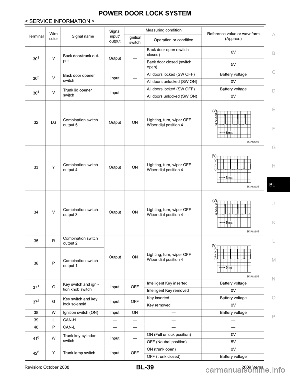
30
1
VBack door/trunk out-
put Output —Back door open (switch
closed) 0V
Back door closed (switch
open) 5V
30 3
VBack door opener
switch Input —All doors locked (SW OFF) Battery voltage
All doors unlocked (SW ON) 0V
30 4
VTrunk lid opener
switch Input —All doors locked (SW OFF) Battery voltage
All doors unlocked (SW ON) 0V
32 LG Combination switch
output 5 Output ONLighting, turn, wiper OFF
Wiper dial position 4
33 Y Combination switch
output 4 Output ON
Lighting, turn, wiper OFF
Wiper dial position 4
34 V Combination switch
output 3 Output ONLighting, turn, wiper OFF
Wiper dial position 4
35 R Combination switch
output 2
Output ONLighting, turn, wiper OFF
Wiper dial position 4
36 P Combination switch
output 1
37 1
GKey switch and igni-
tion knob switch Input OFFIntelligent Key inserted Battery voltage
Intelligent Key removed 0V
37 2
GKey switch and key
lock solenoid Input OFFKey inserted Battery voltage
Key removed 0V
38 W Ignition switch (ON) Input ON — Battery voltage
39 L CAN-H — — — —
40 P CAN-L — — — —
41 6
WTrunk key cylinder
switch Input —ON (Full unlock position) 0V
OFF (Neutral position) 5V
42 6
Y Trunk lamp switch Input OFF ON (trunk open) 0V
OFF (trunk closed) Battery voltage
Terminal
Wire
color Signal name Signal
input/
output Measuring condition
Reference value or waveform
(Approx.)
Ignition
switch Operation or condition SKIA5291E
SKIA5292E
SKIA5291E
SKIA5292E
Page 501 of 4331
BL-40< SERVICE INFORMATION >
POWER DOOR LOCK SYSTEM
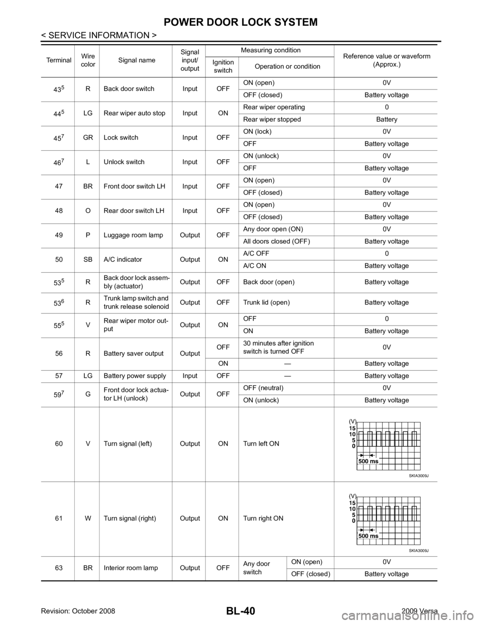
43 5
R Back door switch Input OFF ON (open) 0V
OFF (closed) Ba ttery voltage
44 5
LG Rear wiper auto stop Input ON Rear wiper operating 0
Rear wiper stopped Battery
45 7
GR Lock switch Input OFF ON (lock) 0V
OFF Battery voltage
46 7
L Unlock switch Input OFF ON (unlock) 0V
OFF Battery voltage
47 BR Front door switch LH Input OFF ON (open) 0V
OFF (closed) Ba ttery voltage
48 O Rear door switch LH Input OFF ON (open) 0V
OFF (closed) Ba ttery voltage
49 P Luggage room lamp Output OFF Any door open (ON) 0V
All doors closed (OFF) Battery voltage
50 SB A/C indicator Output ON A/C OFF 0
A/C ON Battery voltage
53 5
RBack door lock assem-
bly (actuator) Output OFF Back door (open) Battery voltage
53 6
RTrunk lamp switch and
trunk release solenoid Output OFF Trunk lid (open) Battery voltage
55 5
VRear wiper motor out-
put Output ONOFF 0
ON Battery voltage
56 R Battery saver output Output OFF
30 minutes after ignition
switch is turned OFF 0V
ON — Battery voltage
57 LG Battery power supply Input OFF — Battery voltage
59 7
GFront door lock actua-
tor LH (unlock) Output OFFOFF (neutral) 0V
ON (unlock) Battery voltage
60 V Turn signal (left) Output ON Turn left ON
61 W Turn signal (right) Output ON Turn right ON
63 BR Interior room lamp Output OFF Any door
switch ON (open) 0V
OFF (closed) Battery voltage
Terminal
Wire
color Signal name Signal
input/
output Measuring condition
Reference value or waveform
(Approx.)
Ignition
switch Operation or condition SKIA3009J
SKIA3009J