Page 3708 of 4331
CONSULT-III Function (BCM) " for switches and
their functions.
OK or NG OK >> GO TO 2.
NG >> Inspect malfunctioning switch system. OK >> Replace BCM. Refer to
BCS-18, " Removal and Installation of BCM " .
NG >> GO TO 3. OK >> GO TO 6.
NG >> GO TO 4. Test item Description
INT LAMP Interior room lamp can be operated by any ON-OFF operations. Item Description CONSULT-III
ROOM LAMP TIMER SET Interior room lamp battery saver timer setting can be changed. MODE 1: 30 min.
MODE 2: 60 min.
ROOM LAMP BAT SAV SET Interior room lamp battery saver control mode can be changed in this mode. Se-
lect interior room lamp battery saver control mode between ON and OFF. ON/OFF
Page 3778 of 4331
ENGINE MAINTENANCE (MR18DE)
MA-35
< SERVICE INFORMATION >
C
D E
F
G H
I
J
K
M A
B MA
N
O P
SPARK PLUG : Removal and Installation
INFOID:0000000004683698
REMOVAL 1. Remove spark plug using suitable tool. CAUTION:
Never drop or shock it.
INSPECTION AFTER REMOVAL CAUTION:
• Never drop or shock spark plug.
• Checking and adjusting spar k plug gap is not required
between change intervals.
• If spark plug tip is covered with carbon, a spark plug cleaner may be used.
• Never use wire brush for cleaning spark plug.
INSTALLATION 1. Install rocker cover gasket to rocker cover. PBIC3871E
SMA806CA
Cleaner air pressure
: Less than 588 kPa (5.88 bar, 6 kg/cm 2
, 85 psi)
Cleaning time : Less than 20 seconds SMA773C
Page 4000 of 4331

PG
N
O P
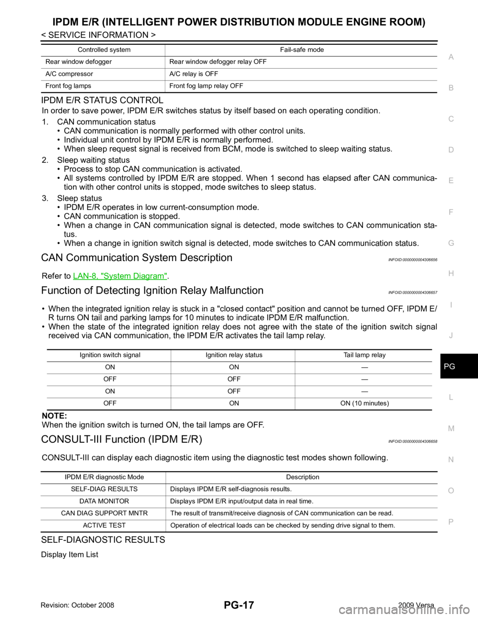
IPDM E/R STATUS CONTROL
In order to save power, IPDM E/R switches status by itself based on each operating condition.
1. CAN communication status • CAN communication is normally performed with other control units.
• Individual unit control by IPDM E/R is normally performed.
• When sleep request signal is received from BCM, mode is switched to sleep waiting status.
2. Sleep waiting status • Process to stop CAN communication is activated.
• All systems controlled by IPDM E/R are stopped. When 1 second has elapsed after CAN communica-
tion with other control units is st opped, mode switches to sleep status.
3. Sleep status • IPDM E/R operates in low current-consumption mode.
• CAN communication is stopped.
• When a change in CAN communication signal is detec ted, mode switches to CAN communication sta-
tus.
• When a change in ignition switch signal is detect ed, mode switches to CAN communication status.
CAN Communication System Description INFOID:0000000004306656
Refer to LAN-8, " System Diagram " .
Function of Detecting Ig nition Relay Malfunction INFOID:0000000004306657
• When the integrated ignition relay is stuck in a "clo sed contact" position and cannot be turned OFF, IPDM E/
R turns ON tail and parking lamps for 10 mi nutes to indicate IPDM E/R malfunction.
• When the state of the integrated ignition relay does not agree with the state of the ignition switch signal
received via CAN communication, the IPDM E/R activates the tail lamp relay.
NOTE:
When the ignition switch is turned ON, the tail lamps are OFF.
CONSULT-III Function (IPDM E/R) INFOID:0000000004306658
CONSULT-III can display each diagnostic item using the diagnostic test modes shown following.
SELF-DIAGNOSTIC RESULTS
Display Item List Rear window defogger Rear window defogger relay OFF
A/C compressor A/C relay is OFF
Front fog lamps Front fog lamp relay OFF Controlled system Fail-safe mode Ignition switch signal Ignition relay status Tail lamp relay
ON ON —
OFF OFF — ON OFF —
OFF ON ON (10 minutes) IPDM E/R diagnostic Mode Description
SELF-DIAG RESULTS Displays IPDM E/R self-diagnosis results.
DATA MONITOR Displays IPDM E/R input/output data in real time.
CAN DIAG SUPPORT MNTR The result of transmit/receive diagnosis of CAN communication can be read. ACTIVE TEST Operation of electrical loads can be checked by sending drive signal to them.
Page 4094 of 4331

RF
N
O P
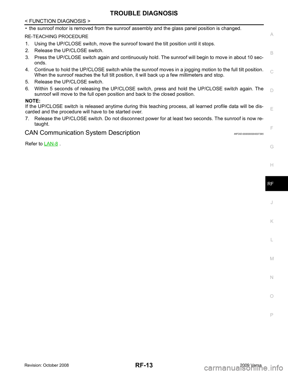
• the sunroof motor is removed from the sunroof
assembly and the glass panel position is changed.
RE-TEACHING PROCEDURE 1. Using the UP/CLOSE switch, move the sunroo f toward the tilt position until it stops.
2. Release the UP/CLOSE switch.
3. Press the UP/CLOSE switch again and continuously hold. The sunroof will begin to move in about 10 sec- onds.
4. Continue to hold the UP/CLOSE switch while the sunroof moves in a jogging motion to the full tilt position.
When the sunroof reaches the full tilt positi on, it will back up a few millimeters and stop.
5. Release the UP/CLOSE switch.
6. Within 5 seconds of releasing the UP/CLOSE s witch, press and hold the UP/CLOSE switch again. The
sunroof will move to the full open pos ition and back to the closed position.
NOTE:
If the UP/CLOSE switch is released anytime during th is teaching process, all learned profile data will be dis-
carded and the procedure will have to be started over.
7. Release the UP/CLOSE switch. Do not disconnect power for at least two seconds. The sunroof is now re-
taught.
CAN Communication System Description INFOID:0000000004307395
Refer to LAN-8 .