2009 NISSAN LATIO service interval
[x] Cancel search: service intervalPage 2428 of 4331
![NISSAN LATIO 2009 Service Repair Manual EC-1072< SERVICE INFOMATION >
[MR TYPE 2]
ON BOARD DIAGNOSTIC (OBD) SYSTEM
tified codes can be identified by using the CONSULT-II I or GST. A DTC will be used as an example for how to
read a code.
A p NISSAN LATIO 2009 Service Repair Manual EC-1072< SERVICE INFOMATION >
[MR TYPE 2]
ON BOARD DIAGNOSTIC (OBD) SYSTEM
tified codes can be identified by using the CONSULT-II I or GST. A DTC will be used as an example for how to
read a code.
A p](/manual-img/5/57359/w960_57359-2427.png)
EC-1072< SERVICE INFOMATION >
[MR TYPE 2]
ON BOARD DIAGNOSTIC (OBD) SYSTEM
tified codes can be identified by using the CONSULT-II I or GST. A DTC will be used as an example for how to
read a code.
A particular trouble code can be identified by the number of four-digit numeral flashes. The “zero” is indicated
by the number of ten flashes. The “A” is indicated by the number of eleven flash. The length of time the
1,000th-digit numeral flashes on and off is 1.2 seconds consisting of an ON (0.6-second) - OFF (0.6-second)
cycle. The 100th-digit numeral and lower digit numer als consist of a 0.3-second ON and 0.3-second OFF
cycle. A change from one digit numeral to another occurs at an interval of 1.0-second OFF. In other words, the
later numeral appears on the display 1.3 seconds after the former numeral has disappeared.
A change from one trouble code to another occu rs at an interval of 1.8-second OFF.
In this way, all the detected malfunctions are classi fied by their DTC numbers. The DTC 0000 refers to no mal-
function. (See EC-1015 )
How to Erase Diagnostic Test Mode II (Self-diagnostic Results)
The DTC can be erased from the back-up memory in the ECM by depressing accelerator pedal.
Refer to "How to Erase Diagnostic Test Mode II (Self-diagnostic Results)".
• If the battery is disconnected, the DTC will be lost from the backup memory within 24 hours.
• Be careful not to erase the stored memo ry before starting trouble diagnoses.
OBD System Operation Chart INFOID:0000000004499928
RELATIONSHIP BETWEEN MIL, 1ST TRIP DTC, DTC, AND DETECTABLE ITEMS
• When a malfunction is detected for the first time, the 1st trip DTC and the 1st trip freeze frame data are
stored in the ECM memory.
• When the same malfunction is detected in two consec utive trips, the DTC and the freeze frame data are
stored in the ECM memory, and the MIL will come on. For details, refer to EC-1051, " Two Trip Detection
Logic " .
• The MIL will go off after the vehicle is driven 3 time s (driving pattern B) with no malfunction. The drive is
counted only when the recorded driving pattern is met (as stored in the ECM). If another malfunction occurs
while counting, the counter will reset.
• The DTC and the freeze frame data will be stored until the vehicle is driven 40 times (driving pattern A) with-
out the same malfunction recurring (except for Misfire and Fuel Injection System). For Misfire and Fuel Injec-
tion System, the DTC and freez e frame data will be stored until the vehicle is driven 80 times (driving pattern PBIB3005E
Page 3087 of 4331
![NISSAN LATIO 2009 Service Repair Manual EM-140< SERVICE INFORMATION >
[MR18DE]
AIR CLEANER AND AIR DUCT
• Align marks.
• Attach each joint securely.
• Screw clamps firmly.
Changing Air Cleaner Filter INFOID:0000000004307131
REMOVAL
1. NISSAN LATIO 2009 Service Repair Manual EM-140< SERVICE INFORMATION >
[MR18DE]
AIR CLEANER AND AIR DUCT
• Align marks.
• Attach each joint securely.
• Screw clamps firmly.
Changing Air Cleaner Filter INFOID:0000000004307131
REMOVAL
1.](/manual-img/5/57359/w960_57359-3086.png)
EM-140< SERVICE INFORMATION >
[MR18DE]
AIR CLEANER AND AIR DUCT
• Align marks.
• Attach each joint securely.
• Screw clamps firmly.
Changing Air Cleaner Filter INFOID:0000000004307131
REMOVAL
1. Push the tabs (A) of both ends of the air cleaner cover (1) into the inside (B).
2. Pull up the air cleaner cover (1) and remove it (C).
3. Remove the air cleaner filter (1) and holder (2) assembly from the air cleaner case.
4. Remove the air cleaner filter (1) from the holder (2).
INSPECTION AFTER REMOVAL
It is necessary to replace the air cleaner filter at the recommended intervals, more often under dusty driving
conditions. Refer to MA-9, " Introduction of Periodic Maintenance " .
INSTALLATION
Installation is in the reverse order of removal.
• Install the air cleaner cover (1) in the direction shown.
• Air cleaner filter (2)
• Holder (3) PBIC3557J
PBIC3558J
PBIC3559J
Page 3101 of 4331
![NISSAN LATIO 2009 Service Repair Manual EM-154< SERVICE INFORMATION >
[MR18DE]
IGNITION COIL, SPARK PLUG AND ROCKER COVER
3. Remove spark plug using suitable tool. CAUTION:
Never drop or shock it.
4. Remove rocker cover. • Loosen bolts in NISSAN LATIO 2009 Service Repair Manual EM-154< SERVICE INFORMATION >
[MR18DE]
IGNITION COIL, SPARK PLUG AND ROCKER COVER
3. Remove spark plug using suitable tool. CAUTION:
Never drop or shock it.
4. Remove rocker cover. • Loosen bolts in](/manual-img/5/57359/w960_57359-3100.png)
EM-154< SERVICE INFORMATION >
[MR18DE]
IGNITION COIL, SPARK PLUG AND ROCKER COVER
3. Remove spark plug using suitable tool. CAUTION:
Never drop or shock it.
4. Remove rocker cover. • Loosen bolts in reverse order as shown.
• Engine front
INSPECTION AFTER REMOVAL
CAUTION:
• Never drop or shock spark plug.
• Checking and adjusting spar k plug gap is not required
between change intervals.
• If spark plug tip is covered with car bon, a spark plug cleaner may be used.
• Never use wire brush for cleaning spark plug.
INSTALLATION
1. Install the rocker cover gasket to the rocker cover. PBIC3871E
PBIC3151J
SMA806CA
Cleaner air pressure
: Less than 588 kPa (5.88 bar, 6 kg/cm 2
, 85 psi)
Cleaning time : Less than 20 seconds SMA773C
Page 3763 of 4331

MA-20< SERVICE INFORMATION >
ENGINE MAINTENANCE (HR16DE)
AIR CLEANER FILTER : Removal and Installation INFOID:0000000004806007
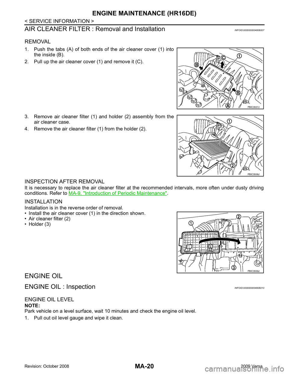
REMOVAL
1. Push the tabs (A) of both ends of the air cleaner cover (1) into the inside (B).
2. Pull up the air cleaner cover (1) and remove it (C).
3. Remove air cleaner filter (1) and holder (2) assembly from the air cleaner case.
4. Remove the air cleaner filter (1) from the holder (2).
INSPECTION AFTER REMOVAL
It is necessary to replace the air cleaner filter at the recommended intervals, more often under dusty driving
conditions. Refer to MA-9, " Introduction of Periodic Maintenance " .
INSTALLATION
Installation is in the reverse order of removal.
• Install the air cleaner cover (1) in the direction shown.
• Air cleaner filter (2)
• Holder (3)
ENGINE OIL
ENGINE OIL : Inspection INFOID:0000000004806010
ENGINE OIL LEVEL
NOTE:
Park vehicle on a level surface, wait 10 minutes and check the engine oil level.
1. Pull out oil level gauge and wipe it clean. PBIC3557J
PBIC3558J
PBIC3559J
Page 3768 of 4331

ENGINE MAINTENANCE (HR16DE)
MA-25
< SERVICE INFORMATION >
C
D E
F
G H
I
J
K
M A
B MA
N
O P
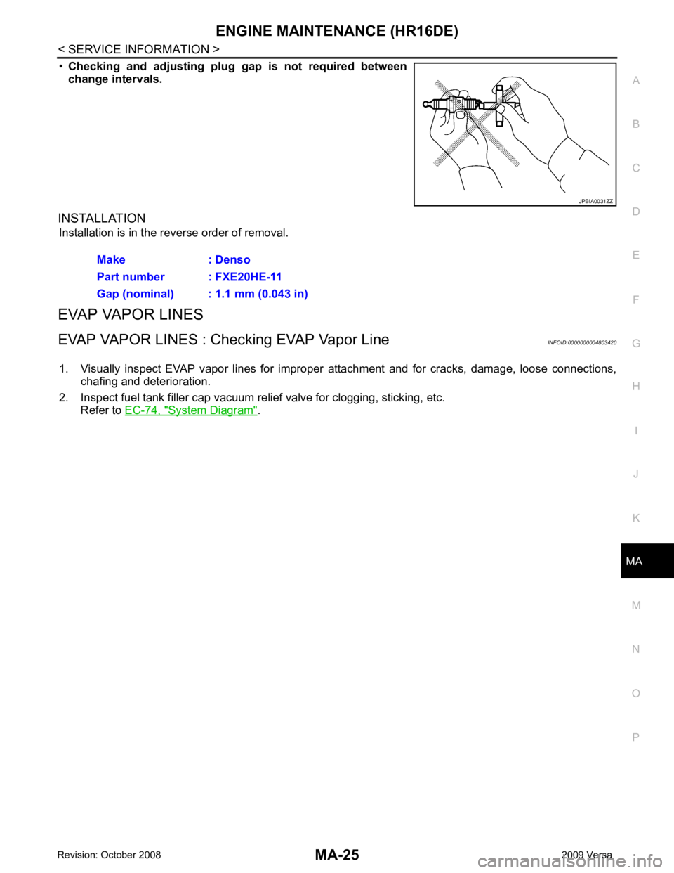
•
Checking and adjusting plug gap is not required between
change intervals.
INSTALLATION Installation is in the reverse order of removal.
EVAP VAPOR LINES
EVAP VAPOR LINES : Checking EVAP Vapor Line INFOID:0000000004803420
1. Visually inspect EVAP vapor lines for improper attachment and for cracks, damage, loose connections,
chafing and deterioration.
2. Inspect fuel tank filler cap vacuum relief valve for clogging, sticking, etc.
Refer to EC-74, " System Diagram " . JPBIA0031ZZ
Make : Denso
Part number : FXE20HE-11
Gap (nominal) : 1.1 mm (0.043 in)
Page 3778 of 4331

ENGINE MAINTENANCE (MR18DE)
MA-35
< SERVICE INFORMATION >
C
D E
F
G H
I
J
K
M A
B MA
N
O P
SPARK PLUG : Removal and Installation
INFOID:0000000004683698
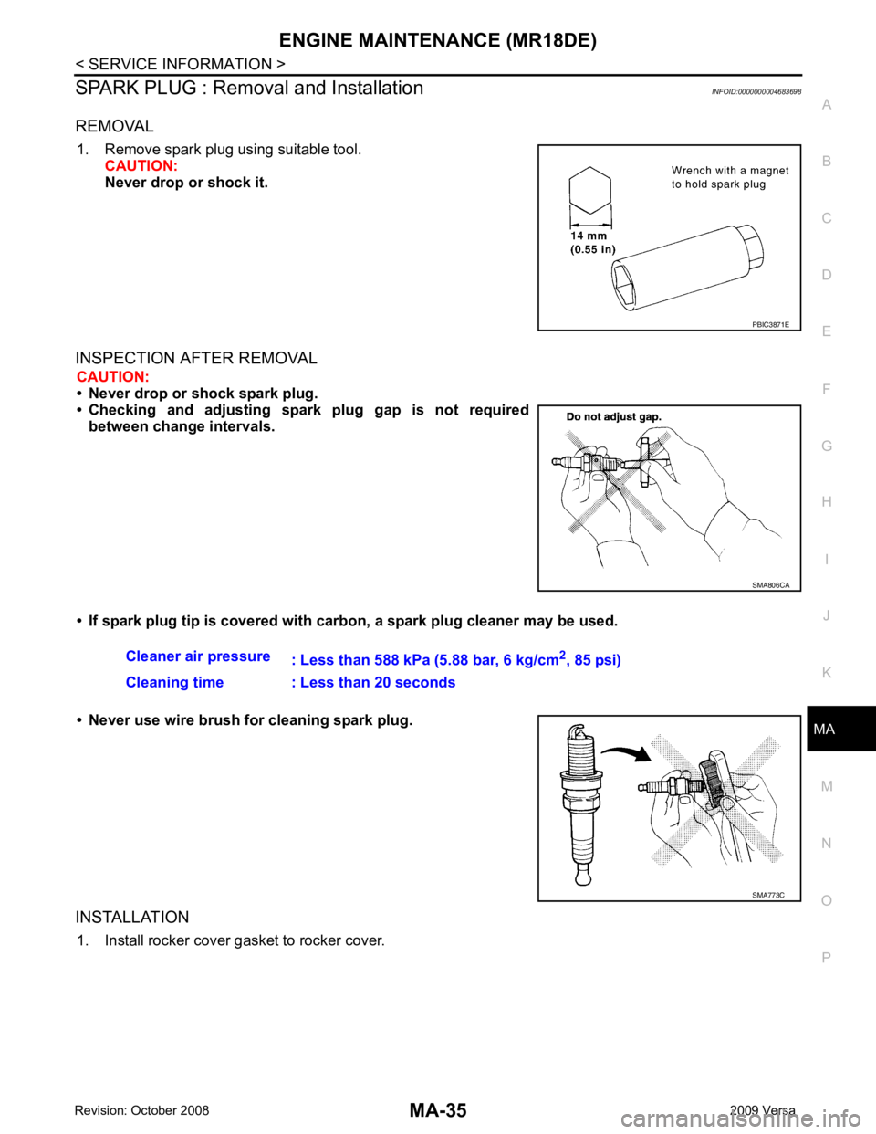
REMOVAL 1. Remove spark plug using suitable tool. CAUTION:
Never drop or shock it.
INSPECTION AFTER REMOVAL CAUTION:
• Never drop or shock spark plug.
• Checking and adjusting spar k plug gap is not required
between change intervals.
• If spark plug tip is covered with carbon, a spark plug cleaner may be used.
• Never use wire brush for cleaning spark plug.
INSTALLATION 1. Install rocker cover gasket to rocker cover. PBIC3871E
SMA806CA
Cleaner air pressure
: Less than 588 kPa (5.88 bar, 6 kg/cm 2
, 85 psi)
Cleaning time : Less than 20 seconds SMA773C
Page 3784 of 4331
![NISSAN LATIO 2009 Service Repair Manual CHASSIS AND BODY MAINTENANCE
MA-41
< SERVICE INFORMATION >
C
D E
F
G H
I
J
K
M A
B MA
N
O P
• : Vehicle front
• Radiator (2)
• CVT fluid cooler hose [inlet side (3)]
• Transaxle assembly (4)
2 NISSAN LATIO 2009 Service Repair Manual CHASSIS AND BODY MAINTENANCE
MA-41
< SERVICE INFORMATION >
C
D E
F
G H
I
J
K
M A
B MA
N
O P
• : Vehicle front
• Radiator (2)
• CVT fluid cooler hose [inlet side (3)]
• Transaxle assembly (4)
2](/manual-img/5/57359/w960_57359-3783.png)
CHASSIS AND BODY MAINTENANCE
MA-41
< SERVICE INFORMATION >
C
D E
F
G H
I
J
K
M A
B MA
N
O P
• : Vehicle front
• Radiator (2)
• CVT fluid cooler hose [inlet side (3)]
• Transaxle assembly (4)
2. Drain CVT fluid from CVT fluid cooler hose [outlet side (1)] and refill with new specified NISSAN CVT fluid in the CVT fluid
charging pipe with the engine running at idle speed.
CAUTION:
Only use the specifi ed NISSAN CVT fluid.
3. Refill until new CVT fluid comes out from CVT fluid cooler hose [outlet side (1)]. NOTE:
About 30 to 50% extra fluid will be required for this procedure.
4. Check fluid level and condition. Refer to MA-39, " CVT FLUID : Checking CVT Fluid (RE0F08B) " .
CAUTION:
Delete CVT fluid deterioration date with CO NSULT-III after changing CVT fluid. Refer to CVT-230," CONSULT-III Function (TRANSMISSION) " .
CLUTCH FLUID
CLUTCH FLUID : Air Bleeding Procedure INFOID:0000000004683730
CAUTION:
Do not spill clutch fluid onto painted surfaces. If it spills, wipe up immediately and wash the affected
area with water.
NOTE:
• Do not use a vacuum assist or any other type of pow er bleeder on this system. Use of a vacuum assist or
power bleeder will not purge all the air from the system.
• Carefully monitor fluid level in reservoir tank during bleeding operation.
1. Fill master cylinder reservoir tank with new clutch fluid.
2. Connect a transparent vinyl tube and container to the bleeding connector (1) on the CSC.
3. Depress and release the clutch pedal slowly and fully 15 times at an interval of two to three seconds and release the clutch
pedal.
4. Push in the lock pin (1) of the bleeding connector (2), and maintain the position. • RS5F91R transaxle models
CAUTION:
Hold the lock pin in to preven t the bleeding connector from
separating when fluid pressure is applied.
Fluid capacity and grade: Refer to
MA-14, " Fluids
and Lubricants " .
SCIA6088E
PCIB1494E
PCIB1495E
Page 3789 of 4331

MA-46< SERVICE INFORMATION >
CHASSIS AND BODY MAINTENANCE
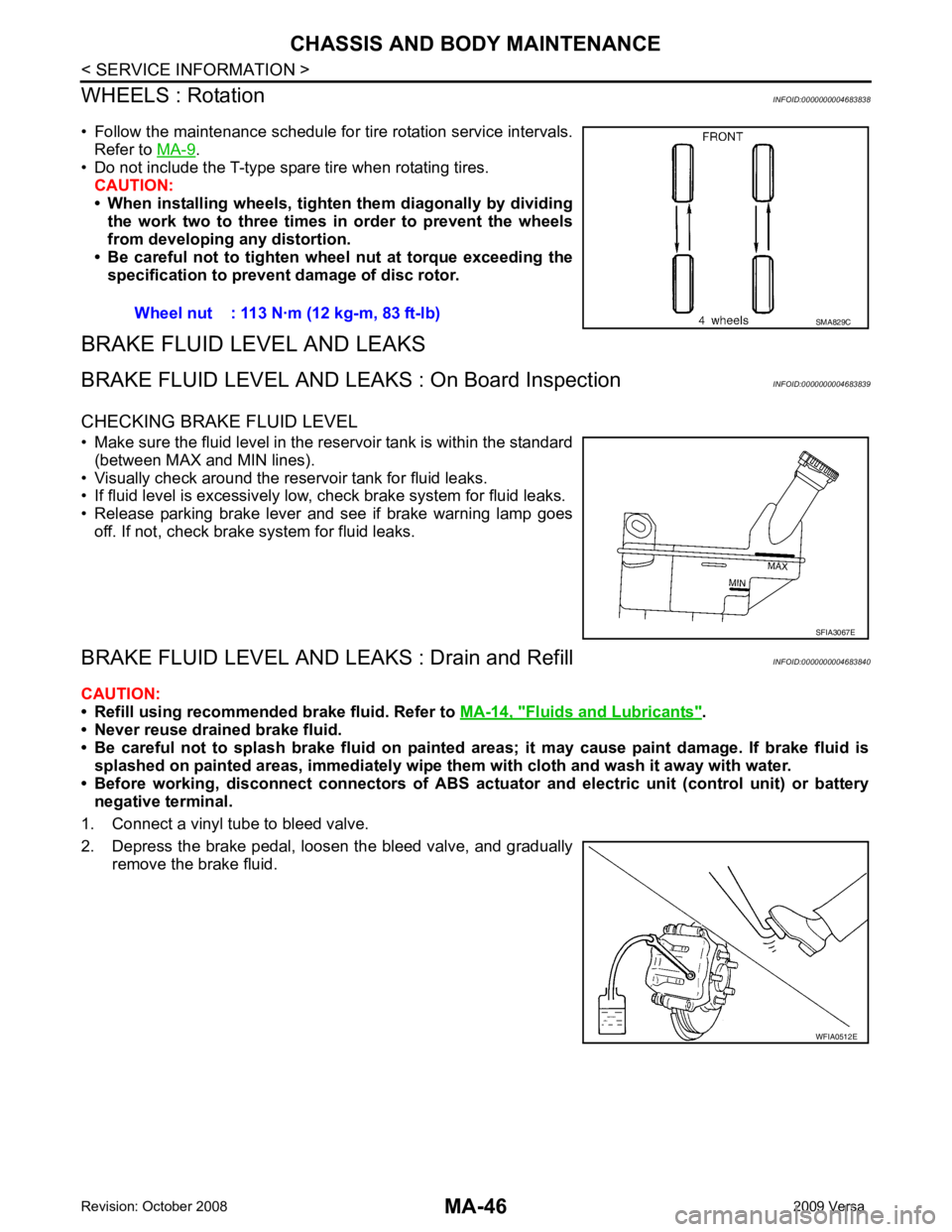
WHEELS : Rotation INFOID:0000000004683838
• Follow the maintenance schedule for tire rotation service intervals. Refer to MA-9 .
• Do not include the T-type spare tire when rotating tires.
CAUTION:
• When installing wheels, tighten them diagonally by dividing
the work two to three times in order to prevent the wheels
from developing any distortion.
• Be careful not to tighten wheel nut at torque exceeding the specification to prevent damage of disc rotor.
BRAKE FLUID LEVEL AND LEAKS
BRAKE FLUID LEVEL AND LEAK S : On Board Inspection INFOID:0000000004683839
CHECKING BRAKE FLUID LEVEL
• Make sure the fluid level in the reservoir tank is within the standard (between MAX and MIN lines).
• Visually check around the reservoir tank for fluid leaks.
• If fluid level is excessively low, check brake system for fluid leaks.
• Release parking brake lever and see if brake warning lamp goes off. If not, check brake system for fluid leaks.
BRAKE FLUID LEVEL AND LE AKS : Drain and Refill INFOID:0000000004683840
CAUTION:
• Refill using recommended brake fluid. Refer to MA-14, " Fluids and Lubricants " .
• Never reuse drained brake fluid.
• Be careful not to splash brake fluid on painted areas; it may cause paint damage. If brake fluid is
splashed on painted areas, immediately wipe th em with cloth and wash it away with water.
• Before working, disconnect connectors of ABS actua tor and electric unit (control unit) or battery
negative terminal.
1. Connect a vinyl tube to bleed valve.
2. Depress the brake pedal, loosen the bleed valve, and gradually remove the brake fluid.Wheel nut : 113 N·m (12 kg-m, 83 ft-lb) SMA829C
SFIA3067E
WFIA0512E