2009 NISSAN LATIO temp gauge
[x] Cancel search: temp gaugePage 1166 of 4331
![NISSAN LATIO 2009 Service Repair Manual CVT-222< SERVICE INFORMATION >
[RE0F08B]
TROUBLE DIAGNOSIS
The CVT fluid temperature rises in the range of 50 - 80 °C (122 - 176 °F) during 10 minutes of driving.
3. After warming up CVT, remove the NISSAN LATIO 2009 Service Repair Manual CVT-222< SERVICE INFORMATION >
[RE0F08B]
TROUBLE DIAGNOSIS
The CVT fluid temperature rises in the range of 50 - 80 °C (122 - 176 °F) during 10 minutes of driving.
3. After warming up CVT, remove the](/manual-img/5/57359/w960_57359-1165.png)
CVT-222< SERVICE INFORMATION >
[RE0F08B]
TROUBLE DIAGNOSIS
The CVT fluid temperature rises in the range of 50 - 80 °C (122 - 176 °F) during 10 minutes of driving.
3. After warming up CVT, remove the oil pressure detection plug and install the oil pressure gauge [special service tool: - (OTC3492)].
CAUTION:
When using the oil pressure gauge, be sure to u se the O-ring attached to the oil pressure detec-
tion plug.
4. Securely engage the parking brake so that the tires do not turn.
5. Start the engine, and then measure the line pressure at both idle and the stall speed.
CAUTION:
• Keep the brake pedal pressed all the way down during
measurement.
• When measuring the line pressure at the stall speed, refer
to "STALL TEST" .
6. After the measurements are complete, install the oil pressure detection plug and tighten to the specified torque below.
CAUTION:
• Do not reuse O-ring.
• Apply CVT fluid to O-ring.
Line Pressure
Judgement of Line Pressure Test SAT513G
: 7.5 N·m (0.77 kg-m, 66 in-lb)
SAT493G
Engine speed
Line pressure kPa (kg/cm
2
, psi)
“R”, “D” and “L” positions
At idle CVT-357, " Line Pressure "
At stall
Page 1314 of 4331
![NISSAN LATIO 2009 Service Repair Manual CONSULT-III display Malfunction Reference page
CAN COMM CIRC [U1000] Malfunction is detected in CAN communication lines.
CAUTION:
Even when there is no malfunct ion on CAN communication system, mal-
f NISSAN LATIO 2009 Service Repair Manual CONSULT-III display Malfunction Reference page
CAN COMM CIRC [U1000] Malfunction is detected in CAN communication lines.
CAUTION:
Even when there is no malfunct ion on CAN communication system, mal-
f](/manual-img/5/57359/w960_57359-1313.png)
CONSULT-III display Malfunction Reference page
CAN COMM CIRC [U1000] Malfunction is detected in CAN communication lines.
CAUTION:
Even when there is no malfunct ion on CAN communication system, mal-
function may be misinterpreted when battery has low voltage (when main-
taining 7 - 8 V for about 2 seconds) or 10A fuse [No. 14, located in the fuse
block (J/B)] is removed. DI-18VEHICLE SPEED CIRC [B2205]
Malfunction is detected when an erroneous speed signal is input.
CAUTION:
Even when there is no malfunction on speed signal system, malfunctions
may be misinterpreted when battery has low voltage (when maintaining 7
- 8 V for about 2 seconds). DI-15Display item [Unit]
MAIN
SIGNALS SELECTION
FROM MENU Contents
SPEED METER [km/h] X X The value of vehicle speed sign
al, which is input from ABS ac-
tuator and electric unit (control unit).
SPEED OUTPUT [km/h] X X The value of vehicle speed signal, which is transmitted to each
unit with CAN communication.
TACHO METER [rpm] X X The value of engine speed signal, which is input from ECM.
W TEMP METER [ °C] X X The value of engine coolant temperature signal, which is input
from ECM.
FUEL METER [lit.] X X The value, which processes a resistance signal from fuel
gauge.
DISTANCE [km] X X The value, which is calculated by vehicle speed signal from
ABS actuator and electric unit (con trol unit), fuel gauge and fuel
consumption signal from ECM.
FUEL W/L [ON/OFF] X X Indicates [ON/OFF] condition of low-fuel warning lamp.
C-ENG W/L [ON/OFF] X Indicates [ON/OFF] condition of malfunction indicator lamp
(MIL).
AIR PRES W/L X Indicates [ON/OFF] condition of low tire pressure warning lamp.
SEAT BELT W/L X Indicates [ON/OFF] condition of seat belt warning lamp.
BUZZER [ON/OFF] X X Indicates [ON/ OFF] condition of buzzer.
DOOR W/L [ON/OFF] X Indicates [ON/OFF] condition of door warning lamp.
HI-BEAM IND [ON/OFF] X Indicat es [ON/OFF] condition of high beam indicator lamp.
Page 1726 of 4331

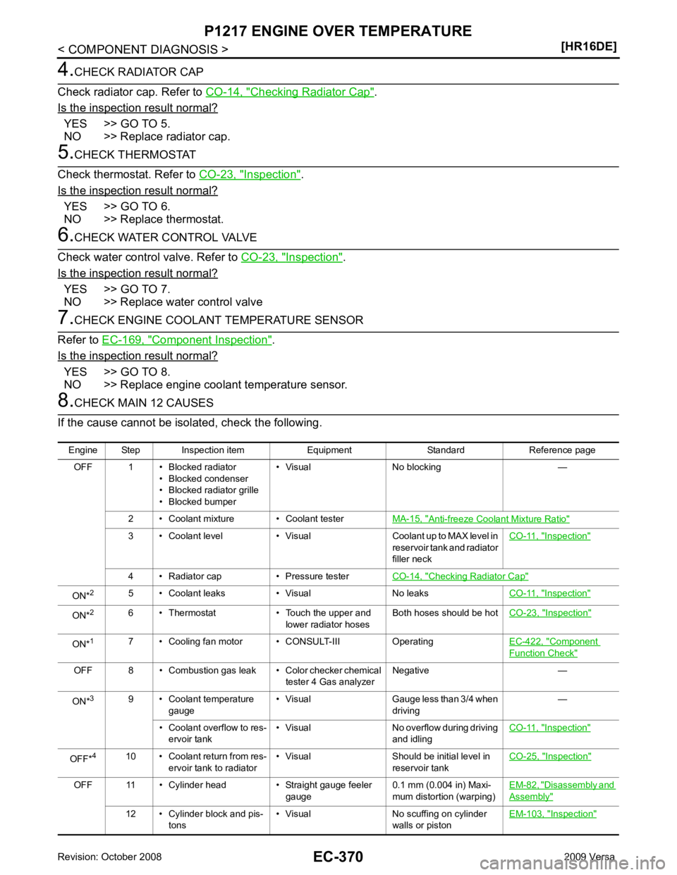
Checking Radiator Cap " .
Is the inspection result normal? YES >> GO TO 5.
NO >> Replace radiator cap. Inspection " .
Is the inspection result normal? YES >> GO TO 6.
NO >> Replace thermostat. Inspection " .
Is the inspection result normal? YES >> GO TO 7.
NO >> Replace water control valve Component Inspection " .
Is the inspection result normal? YES >> GO TO 8.
NO >> Replace engine coolant temperature sensor. Anti-freeze Coolant Mixture Ratio "
3 • Coolant level • Visual Coolant up to MAX level in
reservoir tank and radiator
filler neck CO-11, " Inspection "
4 • Radiator cap • Pressure tester
CO-14, " Checking Radiator Cap "
ON*
2
5 • Coolant leaks • Visual No leaks CO-11, " Inspection "
ON*
2
6 • Thermostat • Touch the upper and
lower radiator hosesBoth hoses should be hot
CO-23, " Inspection "
ON*
1
7 • Cooling fan motor • CONSULT-III Operating EC-422, " Component
Function Check "
OFF 8 • Combustion gas leak • Color checker chemical
tester 4 Gas analyzerNegative —
ON* 3
9 • Coolant temperature
gauge • Visual Gauge less than 3/4 when
driving —
• Coolant overflow to res- ervoir tank • Visual No overflow during driving
and idling CO-11, " Inspection "
OFF*
4
10 • Coolant return from res-
ervoir tank to radiator • Visual Should be initial level in
reservoir tank CO-25, " Inspection "
OFF 11 • Cylinder head • Straight gauge feeler
gauge0.1 mm (0.004 in) Maxi-
mum distortion (warping) EM-82, " Disassembly and
Assembly "
12 • Cylinder block and pis-
tons • Visual No scuffing on cylinder
walls or piston EM-103, " Inspection "
Page 1806 of 4331

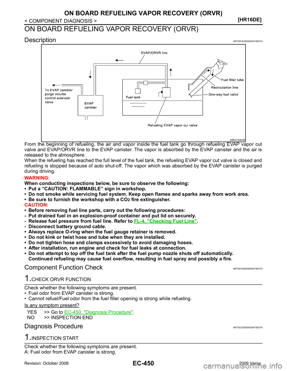
Checking Fuel Line " .
- Disconnect battery ground cable.
• Always replace O-ring when the fu el gauge retainer is removed.
• Do not kink or twist hose and tube when they are installed.
• Do not tighten hose and clamps excessively to avoid damaging hoses.
• After installation, run engine an d check for fuel leaks at connection.
• Do not attempt to top off the fuel tank afte r the fuel pump nozzle shuts off automatically.
Continued refueling may cause fuel overflow, r esulting in fuel spray and possibly a fire.
Component Function Check INFOID:0000000004780375YES >> Go to
EC-450, " Diagnosis Procedure " .
NO >> INSPECTION END
Diagnosis Procedure INFOID:0000000004780376
Page 1889 of 4331

EC
NP
O
ON BOARD REFUELING VAPOR RECOVERY (ORVR)
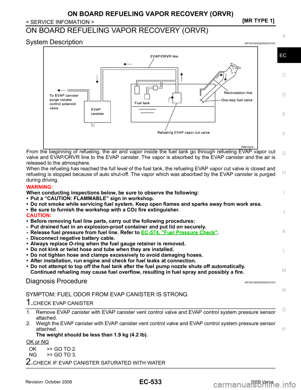
System Description INFOID:0000000004537032
From the beginning of refueling, the air and vapor insi de the fuel tank go through refueling EVAP vapor cut
valve and EVAP/ORVR line to the EVAP canister. The v apor is absorbed by the EVAP canister and the air is
released to the atmosphere.
When the refueling has reached the full level of the fuel tank, the refueling EVAP vapor cut valve is closed and
refueling is stopped because of auto shut-off. The vapor which was absorbed by the EVAP canister is purged
during driving.
WARNING:
When conducting inspectio ns below, be sure to observe the following:
• Put a “CAUTION: FLAMMABL E” sign in workshop.
• Do not smoke while servicing fuel system. Keep open flames and sparks away from work area.
• Be sure to furnish the workshop with a CO 2
fire extinguisher.
CAUTION:
• Before removing fuel line parts, carry out the following procedures:
- Put drained fuel in an explosion-proof containe r and put lid on securely.
- Release fuel pressure from fuel line. Refer to EC-574, " Fuel Pressure Check " .
- Disconnect negative battery cable.
• Always replace O-ring when the fu el gauge retainer is removed.
• Do not kink or twist hose and tube when they are installed.
• Do not tighten hose and clamps excessively to avoid damaging hoses.
• After installation, run engine a nd check for fuel leaks at connection.
• Do not attempt to top off the fuel tank after the fuel pump nozzle shuts off automatically.
Continued refueling may cause fuel overflow, r esulting in fuel spray and possibly a fire.
Diagnosis Procedure INFOID:0000000004537033
SYMPTOM: FUEL ODOR FROM EVAP CANISTER IS STRONG. OK >> GO TO 2.
NG >> GO TO 3.
Page 1922 of 4331
![NISSAN LATIO 2009 Service Repair Manual EC-566< SERVICE INFOMATION >
[MR TYPE 1]
BASIC SERVICE PROCEDURE
BASIC SERVICE PROCEDURE
Basic Inspection INFOID:00000000045370431.
INSPECTION START
1. Check service records for any recent repairs tha NISSAN LATIO 2009 Service Repair Manual EC-566< SERVICE INFOMATION >
[MR TYPE 1]
BASIC SERVICE PROCEDURE
BASIC SERVICE PROCEDURE
Basic Inspection INFOID:00000000045370431.
INSPECTION START
1. Check service records for any recent repairs tha](/manual-img/5/57359/w960_57359-1921.png)
EC-566< SERVICE INFOMATION >
[MR TYPE 1]
BASIC SERVICE PROCEDURE
BASIC SERVICE PROCEDURE
Basic Inspection INFOID:00000000045370431.
INSPECTION START
1. Check service records for any recent repairs that ma y indicate a related malfunction, or a current need for
scheduled maintenance.
2. Open engine hood and check the following:
- Harness connectors for improper connections
- Wiring harness for improper connections, pinches and cut
- Vacuum hoses for splits, kinks and improper connections
- Hoses and ducts for leaks
- Air cleaner clogging
- Gasket
3. Confirm that electrical or mechanical loads are not applied.
- Headlamp switch is OFF.
- Air conditioner switch is OFF.
- Rear window defogger switch is OFF.
- Steering wheel is in the straight-ahead position, etc.
4. Start engine and warm it up until engine coolant temperature indicator points the middle of gauge.
Ensure engine stays below 1,000 rpm.
5. Run engine at about 2,000 rpm for about 2 minutes under no load.
6. Make sure that no DTC is displayed with CONSULT-III or GST.
OK or NG OK >> GO TO 3.
NG >> GO TO 2. 2.
REPAIR OR REPLACE
Repair or replace components as necessary according to corresponding Diagnostic Procedure.
>> GO TO 3. 3.
CHECK TARGET IDLE SPEED
With CONSULT-III
1. Run engine at about 2,000 rpm for about 2 minutes under no load. SEF983U
SEF976U
SEF977U
Page 2100 of 4331
![NISSAN LATIO 2009 Service Repair Manual EC-744< SERVICE INFOMATION >
[MR TYPE 1]
DTC P0171 FUEL INJECTION SYSTEM FUNCTION
1. Listen for an intake air leak after the mass air flow sensor.
2. Check PCV hose connection.
OK or NG OK >> GO TO 3. NISSAN LATIO 2009 Service Repair Manual EC-744< SERVICE INFOMATION >
[MR TYPE 1]
DTC P0171 FUEL INJECTION SYSTEM FUNCTION
1. Listen for an intake air leak after the mass air flow sensor.
2. Check PCV hose connection.
OK or NG OK >> GO TO 3.](/manual-img/5/57359/w960_57359-2099.png)
EC-744< SERVICE INFOMATION >
[MR TYPE 1]
DTC P0171 FUEL INJECTION SYSTEM FUNCTION
1. Listen for an intake air leak after the mass air flow sensor.
2. Check PCV hose connection.
OK or NG OK >> GO TO 3.
NG >> Repair or replace. 3.
CHECK AIR FUEL RATIO (A/F) SENS OR 1 CIRCUIT FOR OPEN AND SHORT
1. Turn ignition switch OFF.
2. Disconnect air fuel ratio (A/F) sensor 1 harness connector (1).
- Air fuel ratio (A/F) sensor 1 (2)
3. Disconnect ECM harness connector.
4. Check harness continuity between the following terminals. Refer to Wiring Diagram.
5. Check harness continuity between ECM terminals 49, 53 or A/F sensor 1 terminals 1, 2 and ground. Refer to Wiring Diagram.
6. Also check harness for short to power.
OK or NG OK >> GO TO 4.
NG >> Repair open circuit or short to ground or short to power in harness or connectors. 4.
CHECK FUEL PRESSURE
1. Release fuel pressure to zero. Refer to EC-574, " Fuel Pressure Check " .
2. Install fuel pressure gauge and check fuel pressure. Refer to EC-574, " Fuel Pressure Check " .
OK or NG OK >> GO TO 6.
NG >> GO TO 5. 5.
DETECT MALFUNCTIONING PART
Check the following.
• Fuel pump and circuit (Refer to EC-991 .)
• Fuel pressure regulator (Refer to EC-574, " Fuel Pressure Check " .)
• Fuel lines (Refer to EM-156 .)
• Fuel filter for clogging
>> Repair or replace. 6.
CHECK MASS AIR FLOW SENSOR
With CONSULT-III
1. Install all removed parts.
2. Start engine and warm it up to normal operating temperature.
3. Check “MASS AIR FLOW” in “DATA MONITOR” mode with CONSULT-III.
With GST A/F sensor 1 terminal ECM terminal
1 49
2 53
Continuity should exist.
Continuity should not exist. BBIA0699E
At idling: Approximately 350 kPa (3.57 kg/cm
2
, 51 psi)
at idling : 1.0 - 4.0 g·m/sec
at 2,500 rpm : 2.0 - 10.0 g·m/sec
Page 2106 of 4331
![NISSAN LATIO 2009 Service Repair Manual EC-750< SERVICE INFOMATION >
[MR TYPE 1]
DTC P0172 FUEL INJECTION SYSTEM FUNCTION
Listen for an intake air leak after the mass air flow sensor.
OK or NG OK >> GO TO 3.
NG >> Repair or replace. 3.
CHEC NISSAN LATIO 2009 Service Repair Manual EC-750< SERVICE INFOMATION >
[MR TYPE 1]
DTC P0172 FUEL INJECTION SYSTEM FUNCTION
Listen for an intake air leak after the mass air flow sensor.
OK or NG OK >> GO TO 3.
NG >> Repair or replace. 3.
CHEC](/manual-img/5/57359/w960_57359-2105.png)
EC-750< SERVICE INFOMATION >
[MR TYPE 1]
DTC P0172 FUEL INJECTION SYSTEM FUNCTION
Listen for an intake air leak after the mass air flow sensor.
OK or NG OK >> GO TO 3.
NG >> Repair or replace. 3.
CHECK AIR FUEL RATIO (A/F) SENS OR 1 CIRCUIT FOR OPEN AND SHORT
1. Turn ignition switch OFF.
2. Disconnect air fuel ratio (A/F) sensor 1 harness connector (1).
- Air fuel ratio (A/F) sensor 1 (2)
3. Disconnect ECM harness connector.
4. Check harness continuity between the following terminals. Refer to Wiring Diagram.
5. Check harness continuity between ECM terminals 49, 53 or A/F sensor 1 terminals 1, 2 and ground. Refer to Wiring Diagram.
6. Also check harness for short to power.
OK or NG OK >> GO TO 4.
NG >> Repair open circuit or short to ground or short to power in harness or connectors. 4.
CHECK FUEL PRESSURE
1. Release fuel pressure to zero. Refer to EC-574, " Fuel Pressure Check " .
2. Install fuel pressure gauge and check fuel pressure. Refer to EC-574, " Fuel Pressure Check " .
OK or NG OK >> GO TO 6.
NG >> GO TO 5. 5.
DETECT MALFUNCTIONING PART
Check the following.
• Fuel pump and circuit (Refer to EC-991 .)
• Fuel pressure regulator (Refer to EC-574, " Fuel Pressure Check " .)
>> Repair or replace. 6.
CHECK MASS AIR FLOW SENSOR
With CONSULT-III
1. Install all removed parts.
2. Start engine and warm it up to normal operating temperature.
3. Check “MASS AIR FLOW” in “DATA MONITOR” mode with CONSULT-III.
With GST
1. Install all removed parts.
2. Start engine and warm it up to normal operating temperature.
3. Check mass air flow sensor signal in Service $01 with GST. A/F sensor 1 terminal ECM terminal
1 49
2 53
Continuity should exist.
Continuity should not exist. BBIA0699E
At idling: Approximately 350 kPa (3.57 kg/cm2, 51 psi)
at idling : 1.0 - 4.0 g·m/sec
at 2,500 rpm : 2.0 - 10.0 g·m/sec