2009 NISSAN LATIO tires
[x] Cancel search: tiresPage 805 of 4331

BR
N
O P
NOISE, VIBRATION AND HARSHN
ESS (NVH) TROUBLESHOOTING
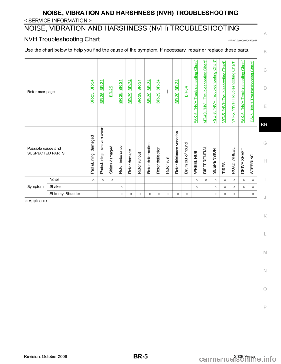
NVH Troubleshooting Chart INFOID:0000000004305889
Use the chart below to help you find t he cause of the symptom. If necessary, repair or replace these parts.
× : ApplicableReference pageBR-25
,
BR-34
BR-25
, BR-34BR-25
BR-29
, BR-34
BR-29
, BR-34
BR-29
, BR-34
BR-29
, BR-34
BR-29
, BR-34—
BR-29, BR-34BR-34
FAX-5, "
NVH Troubleshooting Chart
"
MT-49, "
NVH Troubleshooting Chart
"
FSU-6, "
NVH Troubleshooting Chart
"
WT-5, "
NVH Troubleshooting Chart
"
WT-5, "
NVH Troubleshooting Chart
"
FAX-5, "
NVH Troubleshooting Chart
"
PS-5, "
NVH Troubleshooting Chart
" Possible cause and
SUSPECTED PARTS
Pads/Lining damaged
Pads/Lining - uneven wear
Shims damaged
Rotor imbalance
Rotor damage
Rotor runout
Rotor deformation
Rotor deflection
Rotor rust
Rotor thickness variation
Drum out of round
WHEEL HUB
DIFFERENTIAL
SUSPENSION
TIRES
ROAD WHEEL
DRIVE SHAFT
STEERING
Symptom Noise
× × × × × × × × × ×
Shake × × × × × × ×
Shimmy, Shudder × × × × × × × × × × × ×
Page 927 of 4331

CO
NP
O
Except cool-
ing system
parts mal-
function — Overload on engine
Abusive driving
High engine rpm under no
load
Driving in low gear for ex-
tended time
Driving at extremely high
speed
Power train system mal-
function
—
Installed improper size
wheels and tires
Dragging brakes
Improper ignition timing
Blocked or restricted air
flow Blocked bumper Installed front bumper fas-
cia cover
—
Blocked radiator grille Mud contamination or paper
clogging
Blocked radiator Blocked air flow
Blocked condenser
Installed large fog lamp
Symptom Check items
Page 985 of 4331
![NISSAN LATIO 2009 Service Repair Manual TROUBLE DIAGNOSIS
CVT-41
< SERVICE INFORMATION >
[RE0F08A] D
E
F
G H
I
J
K L
M A
B CVT
N
O P
• Inspect for fluid leakage and check the fluid level. Refer to
CVT-17, " Checking CVT Fluid " .
Fluid NISSAN LATIO 2009 Service Repair Manual TROUBLE DIAGNOSIS
CVT-41
< SERVICE INFORMATION >
[RE0F08A] D
E
F
G H
I
J
K L
M A
B CVT
N
O P
• Inspect for fluid leakage and check the fluid level. Refer to
CVT-17, " Checking CVT Fluid " .
Fluid](/manual-img/5/57359/w960_57359-984.png)
TROUBLE DIAGNOSIS
CVT-41
< SERVICE INFORMATION >
[RE0F08A] D
E
F
G H
I
J
K L
M A
B CVT
N
O P
• Inspect for fluid leakage and check the fluid level. Refer to
CVT-17, " Checking CVT Fluid " .
Fluid Condition Check Inspect the fluid condition.
STALL TEST
Stall Test Procedure 1. Inspect the amount of engine oil. Replenish the engine oil if necessary.
2. Drive for about 10 minutes to warm up the vehicle so that the CVT fluid temperature is 50 to 80 °C (122 to 176 °F). Inspect the
amount of CVT fluid. Replenish if necessary.
3. Securely engage the parking brake so that the tires do not turn.
4. Install a tachometer where it can be seen by driver during test. •It is good practice to mark the point of specified engine
rpm on indicator.
5. Start engine, apply foot brake, and place selector lever in “D” position.Fluid status Conceivable cause Required operation
Varnished (viscous
varnish state) Clutch, brake
scorched Replace the CVT fluid and check the
CVT main unit and the vehicle for
malfunctions (wire harnesses, cool-
er pipes, etc.)
Milky white or
cloudy Water in the fluidReplace the CVT fluid and check for
places where water is getting in.
Large amount of
metal powder mixed
in Unusual wear of
sliding parts within
CVT Replace the CVT fluid and check for
improper operation of the CVT. SAT638A
SAT647B
SAT513G
SAT775B
Page 987 of 4331

CVT
N
O P
The CVT fluid temperature rises in the range of 50 - 80
°C (122 - 176 °F) during 10 minutes of driving.
3. After warming up CVT, remove the oil pressure detection plug and install the oil pressure gauge [special service tool: - (OTC3492)].
CAUTION:
When using the oil pressure gauge, be sure to use the O-ring attached to the oil pressure detec-
tion plug.
4. Securely engage the parking brake so that the tires do not turn.
5. Start the engine, and then measure the line pressure at both idle and the stall speed.
CAUTION:
• Keep the brake pedal pressed all the way down during
measurement.
• When measuring the line pressure at the stall speed, refer
to "STALL TEST" .
6. After the measurements are complete, install the oil pressure detection plug and tighten to the specified torque below.
CAUTION:
• Do not reuse O-ring.
• Apply CVT fluid to O-ring.
Line Pressure
*: Reference values
Judgement of Line Pressure Test
Page 1164 of 4331
![NISSAN LATIO 2009 Service Repair Manual CVT-220< SERVICE INFORMATION >
[RE0F08B]
TROUBLE DIAGNOSIS
• Inspect for fluid leakage and check the fluid level. Refer to CVT-196, " Checking CVT Fluid " .
Fluid Condition Check
Inspect the fluid NISSAN LATIO 2009 Service Repair Manual CVT-220< SERVICE INFORMATION >
[RE0F08B]
TROUBLE DIAGNOSIS
• Inspect for fluid leakage and check the fluid level. Refer to CVT-196, " Checking CVT Fluid " .
Fluid Condition Check
Inspect the fluid](/manual-img/5/57359/w960_57359-1163.png)
CVT-220< SERVICE INFORMATION >
[RE0F08B]
TROUBLE DIAGNOSIS
• Inspect for fluid leakage and check the fluid level. Refer to CVT-196, " Checking CVT Fluid " .
Fluid Condition Check
Inspect the fluid condition.
STALL TEST
Stall Test Procedure
1. Inspect the amount of engine oil. Replenish the engine oil if necessary.
2. Drive for about 10 minutes to wa rm up the vehicle so that the
CVT fluid temperature is 50 to 80 °C (122 to 176 °F). Inspect the
amount of CVT fluid. Replenish if necessary.
3. Securely engage the parking brake so that the tires do not turn.
4. Install a tachometer where it can be seen by driver during test. •It is good practice to mark the point of specified engine
rpm on indicator.
5. Start engine, apply foot brake, and place selector lever in “D” position.Fluid status Conceivable cause Required operation
Varnished (viscous
varnish state) Clutch, brake
scorched Replace the CVT fluid and check the
CVT main unit and the vehicle for
malfunctions (wire harnesses, cool-
er pipes, etc.)
Milky white or
cloudy Water in the fluidReplace the CVT fluid and check for
places where water is getting in.
Large amount of
metal powder mixed
in Unusual wear of
sliding parts within
CVT Replace the CVT fluid and check for
improper operation of the CVT. SAT638A
SAT647B
SAT513G
SAT775B
Page 1166 of 4331
![NISSAN LATIO 2009 Service Repair Manual CVT-222< SERVICE INFORMATION >
[RE0F08B]
TROUBLE DIAGNOSIS
The CVT fluid temperature rises in the range of 50 - 80 °C (122 - 176 °F) during 10 minutes of driving.
3. After warming up CVT, remove the NISSAN LATIO 2009 Service Repair Manual CVT-222< SERVICE INFORMATION >
[RE0F08B]
TROUBLE DIAGNOSIS
The CVT fluid temperature rises in the range of 50 - 80 °C (122 - 176 °F) during 10 minutes of driving.
3. After warming up CVT, remove the](/manual-img/5/57359/w960_57359-1165.png)
CVT-222< SERVICE INFORMATION >
[RE0F08B]
TROUBLE DIAGNOSIS
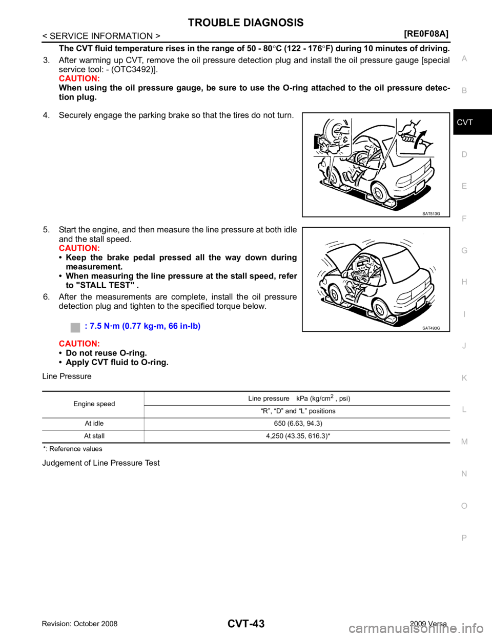
The CVT fluid temperature rises in the range of 50 - 80 °C (122 - 176 °F) during 10 minutes of driving.
3. After warming up CVT, remove the oil pressure detection plug and install the oil pressure gauge [special service tool: - (OTC3492)].
CAUTION:
When using the oil pressure gauge, be sure to u se the O-ring attached to the oil pressure detec-
tion plug.
4. Securely engage the parking brake so that the tires do not turn.
5. Start the engine, and then measure the line pressure at both idle and the stall speed.
CAUTION:
• Keep the brake pedal pressed all the way down during
measurement.
• When measuring the line pressure at the stall speed, refer
to "STALL TEST" .
6. After the measurements are complete, install the oil pressure detection plug and tighten to the specified torque below.
CAUTION:
• Do not reuse O-ring.
• Apply CVT fluid to O-ring.
Line Pressure
Judgement of Line Pressure Test SAT513G
: 7.5 N·m (0.77 kg-m, 66 in-lb)
SAT493G
Engine speed
Line pressure kPa (kg/cm
2
, psi)
“R”, “D” and “L” positions
At idle CVT-357, " Line Pressure "
At stall
Page 3036 of 4331

EM
NP
O
• If items or work required are not covered by the
engine section, follow the procedures in the applica-
ble sections.
• Always use the support poin t specified for lifting.
• Use either 2-pole lift type or separate type lift as best you can. If board-on type is used for unavoid-
able reasons, support at the rear axle jacking point with a transmission jack or similar tool before
starting work, in prepar ation for the backward shif t of center of gravity.
• For supporting points fo r lifting and jacking point at rear axle, refer to GI-38, " Garage Jack and
Safety Stand and 2-Pole Lift " .
REMOVAL
Outline Remove the engine and the transaxle assembly from t he vehicle downward. Separate the engine and the tran-
saxle.
Preparation 1. Remove the hood assembly. Refer to BL-14, " Removal and Installation " .
2. Remove the cowl top cover and cowl top extension assembly. Refer to EI-22, " Removal and Installation " .
3. Release fuel pressure. Refer to EC-498, " Inspection " .
4. Drain engine coolant from radiator. Refer to CO-11, " Changing Engine Coolant " .
CAUTION:
• Perform this step when the engine is cold.
• Never spill engine coolant on drive belt.
5. Drain the transmission fluid. Refer to MT-10, " Draining " (M/T),
AT-17, " Changing A/T Fluid " (A/T).
6. Remove the following parts. • Engine undercover
• Front road wheels and tires: Refer to WT-7, " Rotation " .
• Front fender protector (RH and LH): Refer to EI-24, " Removal and Installation " .
• Battery and battery tray: Refer to SC-7, " Removal and Installation " .
• Drive belt: Refer to EM-15, " Removal and Installation " .
• Air duct and air cleaner case assembly: Refer to EM-26, " Exploded View " .
• Radiator hose (upper and lower): Refer to CO-16, " Component " .
• Disconnect cooling fan controller wiring harness.
• Remove coolant reservoir tank.
• Remove fan shroud and cooling fan assembly. Refer to CO-18, " Component (Models with A/C) " or
CO- 18, " Component (Models without A/C) " .
Engine Room LH 1. Disconnect all connections of engine harness around the engine mounting insulator (LH), and then tem- porarily secure the engine harness into the engine side.
CAUTION:
Protect connectors using a resin bag against foreign materials.
2. Remove ground cable at transaxle side.
3. Disconnect fuel feed hose at engine side. Refer to EM-34, " Exploded View " .
4. Disconnect EVAP purge hose and brake booster vacuum hose.
5. Disconnect heater hoses, and install plugs them to prevent engine coolant from draining. Refer to CO-16," Component " .
6. Disconnect control linkage from transaxle. Refer to AT-212, " Control Device Removal and Installation " (A/
T), MT-13, " Exploded View " (M/T).
7. Disconnect the clutch tube at tr ansmission side (if equipped). Refer to CL-14, " Removal and Installation " .
Engine Room RH 1. Remove ground cable between front cover and vehicle.
2. Remove generator and generator bracket; Refer to SC-25, " Removal and Installation " .
3. Remove A/C compressor with piping connected from t he engine. Temporarily secure it on the vehicle side
with a rope to avoid putting load on it. (if equipped) Refer to MTC-78, " Removal and Installation of Com-
pressor - HR16DE " .
Vehicle Underbody
Page 3200 of 4331

FAX
N
O P
NOISE, VIBRATION AND HARSHN
ESS (NVH) TROUBLESHOOTING
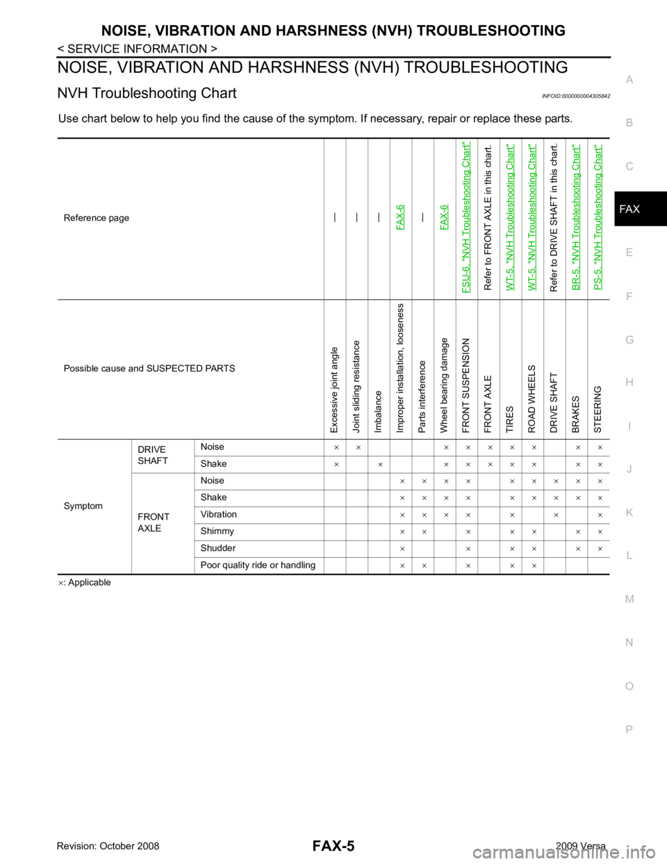
NVH Troubleshooting Chart INFOID:0000000004305842
Use chart below to help you find the cause of the symptom. If necessary, repair or replace these parts.
× : ApplicableReference page—
—
—
FAX-6—
FAX-6
FSU-6, "
NVH Troubleshooting Chart
"
Refer to FRONT AXLE in this chart.
WT-5, "
NVH Troubleshooting Chart
"
WT-5, "
NVH Troubleshooting Chart
"
Refer to DRIVE SHAFT in this chart. BR-5, "
NVH Troubleshooting Chart
"
PS-5, "
NVH Troubleshooting Chart
" Possible cause and
SUSPECTED PARTS
Excessive joint angle
Joint sliding resistance
Imbalance
Improper installation, looseness
Parts interference
Wheel bearing damage
FRONT SUSPENSION
FRONT AXLE
TIRES
ROAD WHEELS
DRIVE SHAFT
BRAKES
STEERING
Symptom DRIVE
SHAFT Noise
× × × × × × × × ×
Shake × × × × × × × × ×
FRONT
AXLE Noise
× × × × × × × × ×
Shake × × × × × × × × ×
Vibration × × × × × × ×
Shimmy × × × × × × ×
Shudder × × × × × ×
Poor quality ride or handling × × × × ×