2009 NISSAN LATIO ESP
[x] Cancel search: ESPPage 38 of 4331
AT
N
O P
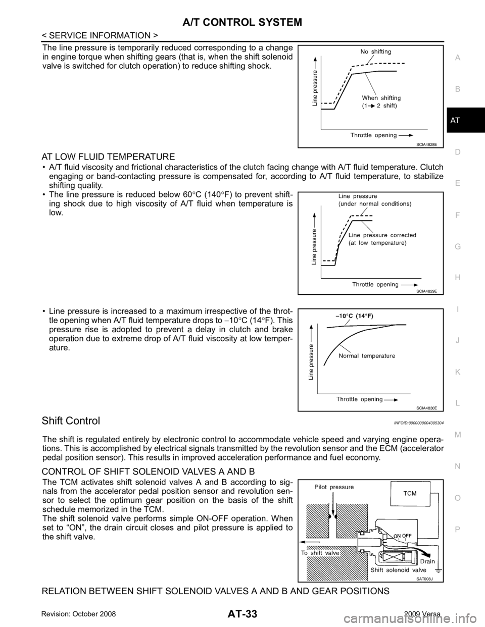
The line pressure is temporarily reduced corresponding to a change
in engine torque when shifting gears (that is, when the shift solenoid
valve is switched for clutch operation) to reduce shifting shock.
AT LOW FLUID TEMPERATURE • A/T fluid viscosity and frictional characteristics of t he clutch facing change with A/T fluid temperature. Clutch
engaging or band-contacting pressure is compensated for, according to A/T fluid temperature, to stabilize
shifting quality.
• The line pressure is reduced below 60 °C (140 °F) to prevent shift-
ing shock due to high viscosity of A/T fluid when temperature is
low.
• Line pressure is increased to a maximum irrespective of the throt- tle opening when A/T fluid temperature drops to −10 °C (14 °F). This
pressure rise is adopted to prevent a delay in clutch and brake
operation due to extreme drop of A/T fluid viscosity at low temper-
ature.
Shift Control INFOID:0000000004305304
The shift is regulated entirely by electronic cont rol to accommodate vehicle speed and varying engine opera-
tions. This is accomplished by electrical signals trans mitted by the revolution sensor and the ECM (accelerator
pedal position sensor). This results in improved acceleration performance and fuel economy.
CONTROL OF SHIFT SOLENOID VALVES A AND B The TCM activates shift solenoid valves A and B according to sig-
nals from the accelerator pedal position sensor and revolution sen-
sor to select the optimum gear pos ition on the basis of the shift
schedule memorized in the TCM.
The shift solenoid valve performs simple ON-OFF operation. When
set to “ON”, the drain circuit closes and pilot pressure is applied to
the shift valve.
RELATION BETWEEN SHIFT SOLENOID VALVES A AND B AND GEAR POSITIONS SAT008J
Page 42 of 4331

AT
N
O P
Control Valve
INFOID:0000000004305307
FUNCTION OF CONTROL VALVES
Centrifugal Cancel Mechanism INFOID:0000000004305308
FUNCTION The centrifugal cancel mechanism is a mechanism to c ancel the centrifugal hydraulic pressure instead of the
conventional check balls. It cancels the centrifugal hy draulic pressure which is generated as high clutch drum
rotates, and it allows for preventing high clutch from dragging and for providing stable high clutch piston press-
ing force in all revolution speeds.
STRUCTURE/OPERATION Valve name Function
Pressure regulator valve, plug and sleeve
plug Regulates oil discharged from the oil pump to provide optimum line pressure for all driving
conditions.
Pressure modifier valve and sleeve Used as a signal supplementary valve to the pressure regulator valve. Regulates pres- sure-modifier pressure (signal pressure) which controls optimum line pressure for all driv-
ing conditions.
Pilot valve Regulates line pressure to maintain a constant pilot pressure level which controls lock-up mechanism, overrun clutch, shift timing.
Accumulator control valve Regulates accumulator back-pressure to pressure suited to driving conditions.
Manual valve Directs line pressure to oil circuits corresponding to select positions. Hydraulic pressure drains when the shift lever is in Neutral.
Shift valve A Simultaneously switches three oil circuits using output pressure of shift solenoid valve A to meet driving conditions (vehicle speed, throttle opening, etc.).
Provides automatic downshifting and upshifting (1st → 2nd → 3rd → 4th gears/4th → 3rd
→ 2nd → 1st gears) in combination with shift valve B.
Shift valve B Simultaneously switches two oil circuits using output pressure of shift solenoid valve B in relation to driving conditions (vehicle speed, throttle opening, etc.).
Provides automatic downshifting and upshifting (1st → 2nd → 3rd → 4th gears/4th → 3rd
→ 2nd → 1st gears) in combination with shift valve A.
Overrun clutch control valve Switches hydraulic circuits to prevent engagement of the overrun clutch simultaneously with application of the brake band in D4. (Interlocking occurs if the overrun clutch engages
during D 4.)
1st reducing valve Reduces low & reverse brake pressure to dampen engine-brake shock when downshift- ing from the 1st position 12 to 1 1.
Overrun clutch reducing valve Reduces oil pressure directed to the overrun clutch and prevents engine-brake shock. In the 1st and 2nd positions, line pressure acts on the overrun clutch reducing valve to
increase the pressure-regulating point, with resultant engine brake capability.
Torque converter relief valve Prevents an excessive rise in torque converter pressure.
Torque converter clutch control valve, plug
and sleeve Activates or inactivates the lock-up function.
Also provides smooth lock-up through transient application and release of the lock-up
system.
1-2 accumulator valve and piston Lessens the shock find when the 2nd gear band servo contracts, and provides smooth shifting.
3-2 timing valve Switches the pace that oil pressure is released depending on vehicle speed; maximizes the high clutch release timing, and allows for soft downshifting.
Shuttle valve Determines if the overrun clutch solenoid valve should control the 3-2 timing valve or the overrun clutch control valve and switches between the two.
Cooler check valve At low speeds and with a small load when a little heat is generated, saves the volume of cooler flow, and stores the oil pressure for lock-up.
Page 44 of 4331
AT
N
O P
ON BOARD DIAGNOSTIC (OBD) SYSTEM
Introduction INFOID:0000000004305309
A/T system has two self-diagnostic systems.
The first is emission-related on boar d diagnostic system (OBD-II) performed by the TCM in combination with
the ECM. The malfunction is indicated by the MIL (malf unction indicator lamp) and is stored as a DTC in the
ECM memory but not the TCM memory.
The second is the TCM original self-diagnosis indicated by the OD OFF indicator lamp. The malfunction is
stored in the TCM memory. The detected items are ov erlapped with OBD-II self-diagnostic items. For detail,
refer to AT-79, " CONSULT-III Function (TRANSMISSION) " .
OBD-II Function for A/T System INFOID:0000000004305310
The ECM provides emission-related on board diagnostic (O BD-II) functions for the A/T system. One function
is to receive a signal from the TCM used with OBD-rela ted parts of the A/T system. The signal is sent to the
ECM when a malfunction occurs in the corresponding OBD-re lated part. The other function is to indicate a
diagnostic result by means of the MIL (malfunction indica tor lamp) on the instrument panel. Sensors, switches
and solenoid valves are used as sensing elements.
The MIL automatically illuminates in One or Two Trip Detection Logic when a malfunction is sensed in relation
to A/T system parts.
One or Two Trip Detection Logic of OBD-II INFOID:0000000004305311
ONE TRIP DETECTION LOGIC If a malfunction is sensed during the first test drive, the MIL will illuminate and the malfunction will be stored in
the ECM memory as a DTC. The TCM is not provided with such a memory function.
TWO TRIP DETECTION LOGIC When a malfunction is sensed during the first test drive, it is stored in the ECM memory as a 1st trip DTC
(diagnostic trouble code) or 1st trip freeze frame data. At this point, the MIL will not illuminate. — 1st trip
If the same malfunction as that experienced during the fi rst test drive is sensed during the second test drive,
the MIL will illuminate. — 2nd trip
The “trip” in the “One or Two Trip Detection Logic” m eans a driving mode in which self-diagnosis is performed
during vehicle operation.
OBD-II Diagnostic Trouble Code (DTC) INFOID:0000000004305312
HOW TO READ DTC AND 1ST TRIP DTC DTC and 1st trip DTC can be read by the following methods.
( with CONSULT-III or GST) CONSULT-III or GST (Generic Scan Tool) Examples: P0705, P0720 etc.
These DTC are prescribed by SAE J2012.
(CONSULT-III also displays the malfunctioning component or system.)
• 1st trip DTC No. is the same as DTC No.
• Output of the diagnostic troubl e code indicates that the indicated circuit has a malfunction. How-
ever, in case of the Mode II and GST, they do not indicate whether the malfunction is still occurring or
occurred in the past and returned to normal.
CONSULT-III can identify them as shown below, therefore, CONS ULT-III (if available) is recom-
mended.
DTC or 1st trip DTC of a malfunction is displayed in SELF-DIAGNOSTIC RESULTS mode for “ENGINE” with
CONSULT-III. Time data indicates how many times the vehicle was driven after the last detection of a DTC.
If the DTC is being detected curr ently, the time data will be “0”.
If a 1st trip DTC is stored in the ECM, the time data will be “1t”.
Freeze Frame Data and 1st Trip Freeze Frame Data The ECM has a memory function, which stores the driv ing condition such as fuel system status, calculated
load value, engine coolant temperature, short term f uel trim, long term fuel trim, engine speed and vehicle
speed at the moment the ECM detects a malfunction.
Page 59 of 4331
AT-54< SERVICE INFORMATION >
TROUBLE DIAGNOSIS
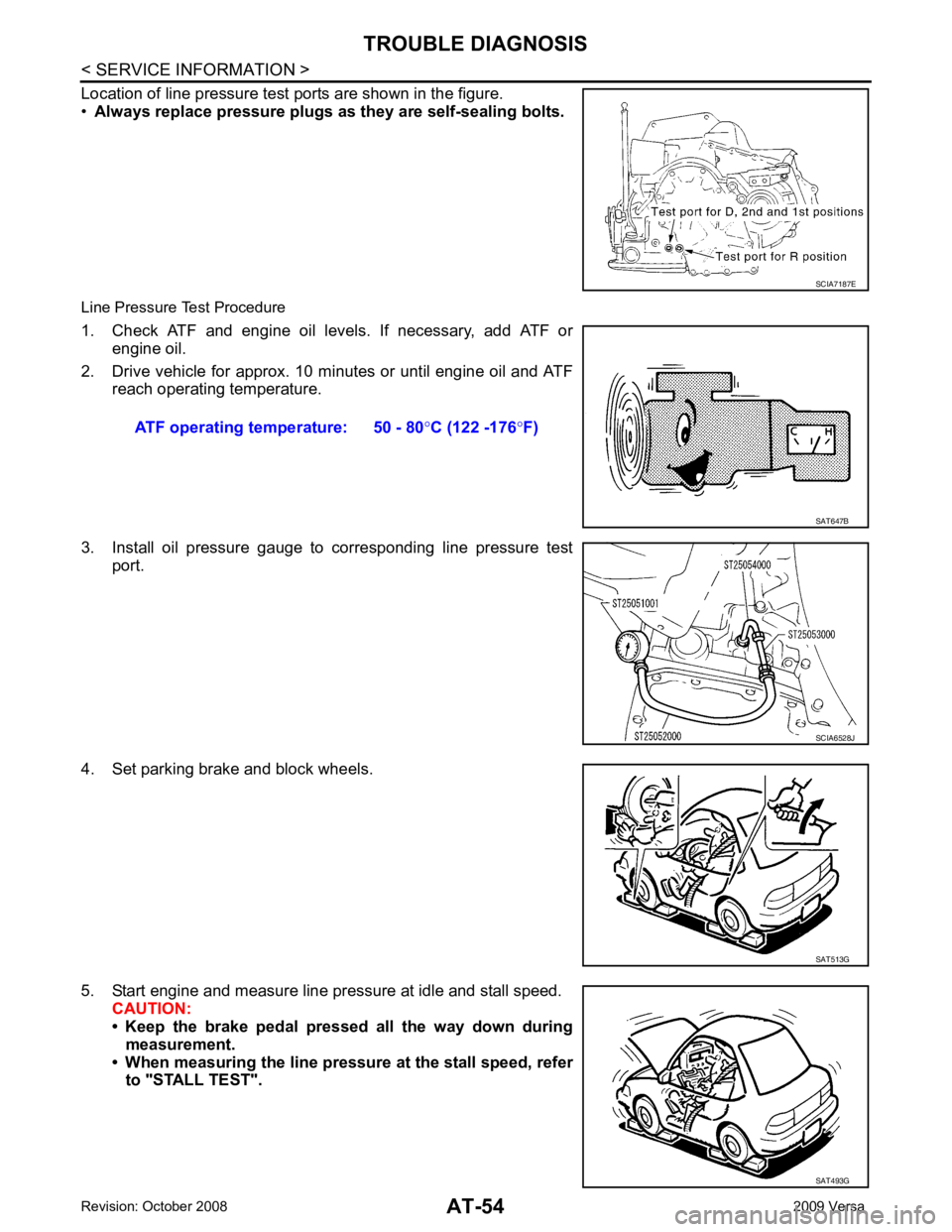
Location of line pressure test ports are shown in the figure.
• Always replace pressure plugs as they are self-sealing bolts.
Line Pressure Test Procedure
1. Check ATF and engine oil levels. If necessary, add ATF or engine oil.
2. Drive vehicle for approx. 10 minutes or until engine oil and ATF reach operating temperature.
3. Install oil pressure gauge to corresponding line pressure test port.
4. Set parking brake and block wheels.
5. Start engine and measure line pressure at idle and stall speed. CAUTION:
• Keep the brake pedal pressed all the way down during
measurement.
• When measuring the line pressure at the stall speed, refer to "STALL TEST". SCIA7187E
ATF operating temperature: 50 - 80
°C (122 -176 °F) SAT647B
SCIA6528J
SAT513G
SAT493G
Page 144 of 4331
AT
N
O P
DTC P0750 SHIFT SOLENOID VALVE A
Description INFOID:0000000004305411
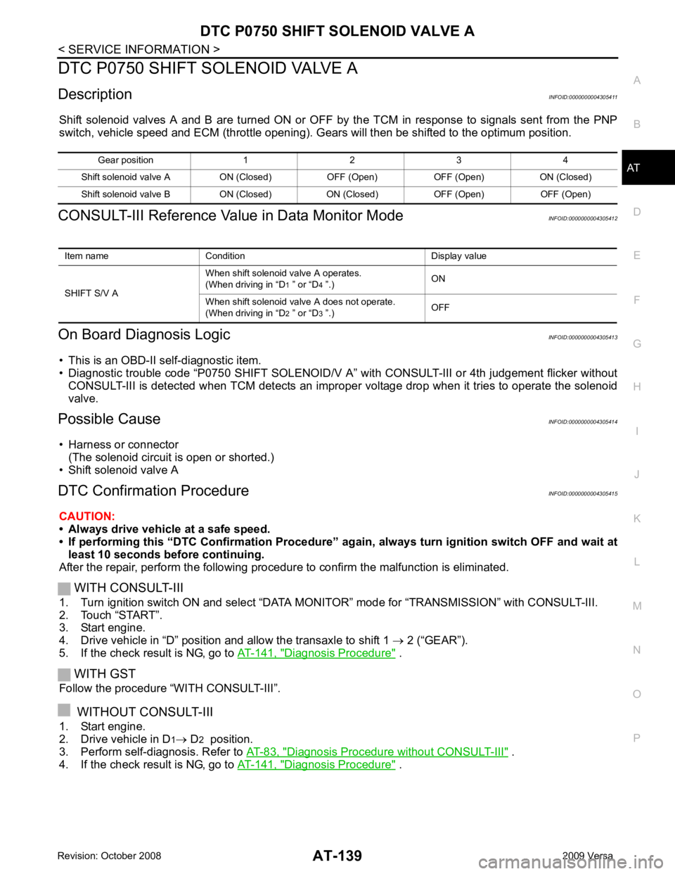
Shift solenoid valves A and B are turned ON or OFF by the TCM in response to signals sent from the PNP
switch, vehicle speed and ECM (throttle opening). G ears will then be shifted to the optimum position.
CONSULT-III Reference Val ue in Data Monitor Mode INFOID:0000000004305412
On Board Diagnosis Logic INFOID:0000000004305413
• This is an OBD-II self-diagnostic item.
• Diagnostic trouble code “P0750 SHIFT SOLENOID/V A” with CONSULT-III or 4th judgement flicker without
CONSULT-III is detected when TCM detects an improper voltage drop when it tries to operate the solenoid
valve.
Possible Cause INFOID:0000000004305414
• Harness or connector (The solenoid circuit is open or shorted.)
• Shift solenoid valve A
DTC Confirmation Procedure INFOID:0000000004305415
CAUTION:
• Always drive vehicle at a safe speed.
• If performing this “DTC Confirmation Procedure” again, always turn ignition switch OFF and wait at
least 10 seconds before continuing.
After the repair, perform the following procedure to confirm the malfunction is eliminated.
WITH CONSULT-III
1. Turn ignition switch ON and select “DATA MO NITOR” mode for “TRANSMISSION” with CONSULT-III.
2. Touch “START”.
3. Start engine.
4. Drive vehicle in “D” position and allow the transaxle to shift 1 → 2 (“GEAR”).
5. If the check result is NG, go to AT-141, " Diagnosis Procedure " .
WITH GST
Follow the procedure “WITH CONSULT-III”.
WITHOUT CONSULT-III
1. Start engine.
2. Drive vehicle in D 1→ D 2 position.
3. Perform self-diagnosis. Refer to AT-83, " Diagnosis Procedure without CONSULT-III " .
4. If the check result is NG, go to AT-141, " Diagnosis Procedure " .
Gear position 1 2 3 4
Shift solenoid valve A ON (Closed) OFF (Open) OFF (Open) ON (Closed)
Shift solenoid valve B ON (Closed) ON (Closed) OFF (Open) OFF (Open) Item name Condition Display value
SHIFT S/V A When shift solenoid valve A operates.
(When driving in “D 1 ” or “D 4 ”.) ON
When shift solenoid valve A does not operate.
(When driving in “D 2 ” or “D 3 ”.) OFF
Page 154 of 4331
AT
N
O P
DTC P1760 OVERRUN CLUTCH SOLENOID VALVE
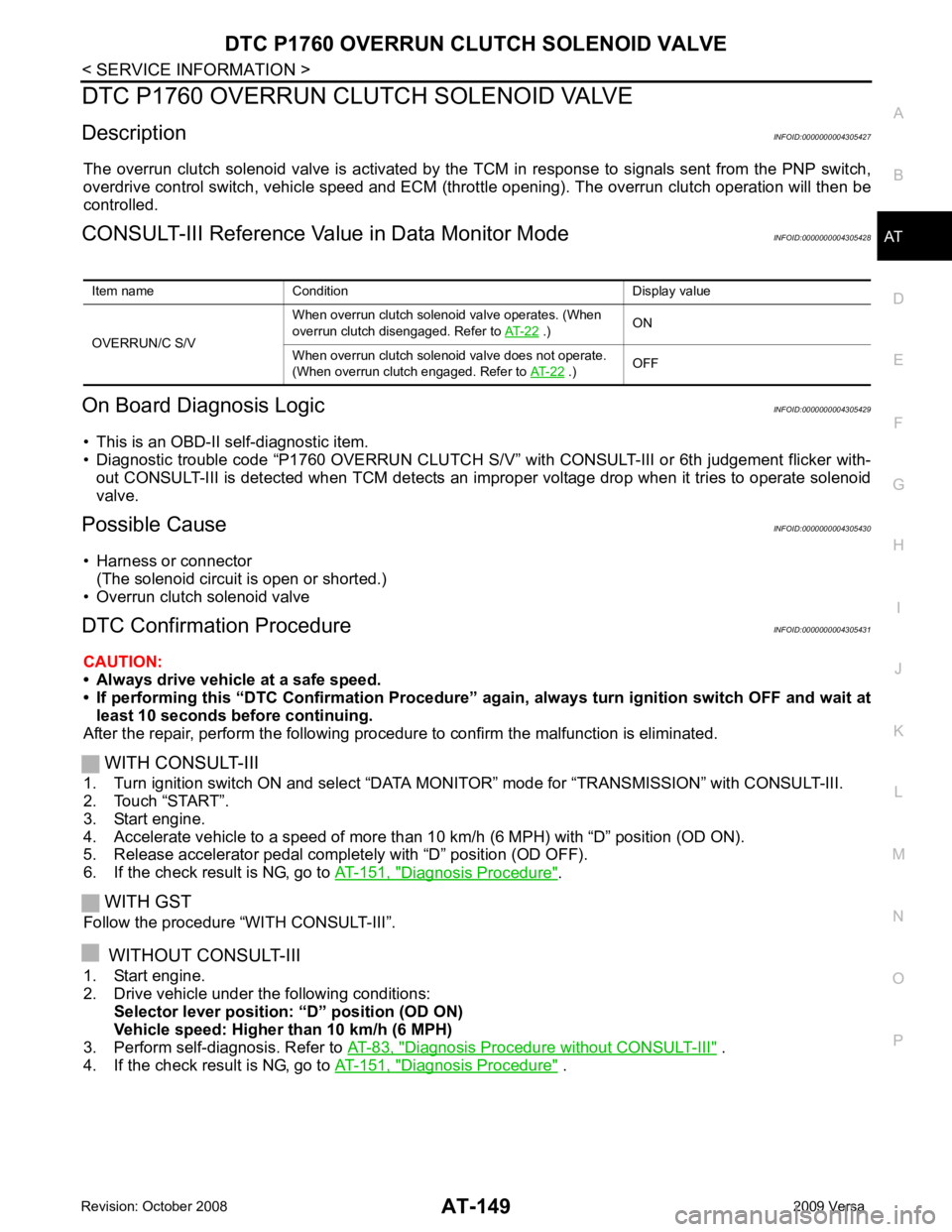
Description INFOID:0000000004305427
The overrun clutch solenoid valve is activated by the TCM in response to signals sent from the PNP switch,
overdrive control switch, vehicle speed and ECM (throt tle opening). The overrun clutch operation will then be
controlled.
CONSULT-III Reference Val ue in Data Monitor Mode INFOID:0000000004305428
On Board Diagnosis Logic INFOID:0000000004305429
• This is an OBD-II self-diagnostic item.
• Diagnostic trouble code “P1760 OVERRUN CLUTCH S/V” wit h CONSULT-III or 6th judgement flicker with-
out CONSULT-III is detected when TCM detects an im proper voltage drop when it tries to operate solenoid
valve.
Possible Cause INFOID:0000000004305430
• Harness or connector (The solenoid circuit is open or shorted.)
• Overrun clutch solenoid valve
DTC Confirmation Procedure INFOID:0000000004305431
CAUTION:
• Always drive vehicle at a safe speed.
• If performing this “DTC Confirmation Procedure” again, always turn ignition switch OFF and wait at
least 10 seconds before continuing.
After the repair, perform the following procedure to confirm the malfunction is eliminated.
WITH CONSULT-III
1. Turn ignition switch ON and select “DATA MO NITOR” mode for “TRANSMISSION” with CONSULT-III.
2. Touch “START”.
3. Start engine.
4. Accelerate vehicle to a speed of more than 10 km/h (6 MPH) with “D” position (OD ON).
5. Release accelerator pedal completely with “D” position (OD OFF).
6. If the check result is NG, go to AT-151, " Diagnosis Procedure " .
WITH GST
Follow the procedure “WITH CONSULT-III”.
WITHOUT CONSULT-III
1. Start engine.
2. Drive vehicle under the following conditions: Selector lever position: “D” position (OD ON)
Vehicle speed: Higher than 10 km/h (6 MPH)
3. Perform self-diagnosis. Refer to AT-83, " Diagnosis Procedure without CONSULT-III " .
4. If the check result is NG, go to AT-151, " Diagnosis Procedure " .
Item name Condition Display value
OVERRUN/C S/V When overrun clutch solenoid valve operates. (When
overrun clutch disengaged. Refer to AT-22 .)
ON
When overrun clutch solenoid valve does not operate.
(When overrun clutch engaged. Refer to AT-22 .)
OFF
Page 212 of 4331

AT
N
O P
A/T SHIFT LOCK SYSTEM
Description INFOID:0000000004305498
• The mechanical key interlock mechanism also operates as a shift lock: With the ignition switch turned to ON, selector lever cannot be shifted from “P” position to any other position
unless brake pedal is depressed.
With the key removed, selector lever cannot be shifted from “P” position to any other position.
The key cannot be removed unless selector lever is placed in “P” position.
• The shift lock and key interlock mechanisms are controlled by the ON-OFF operation of the shift lock sole-
noid and by the operation of the rotator and sli der located inside key cylinder, respectively.
Shift Lock System Parts Location INFOID:0000000004305499
1. Key interlock cable 2. Key cylinder 3. Stop lamp switch
4. Brake pedal 5. Shift lock release button 6. Key interlock cable
7. Shift lock solenoid 8. Park position switch
Page 234 of 4331
AT
N
O P
REMOVAL AND INSTALLATION
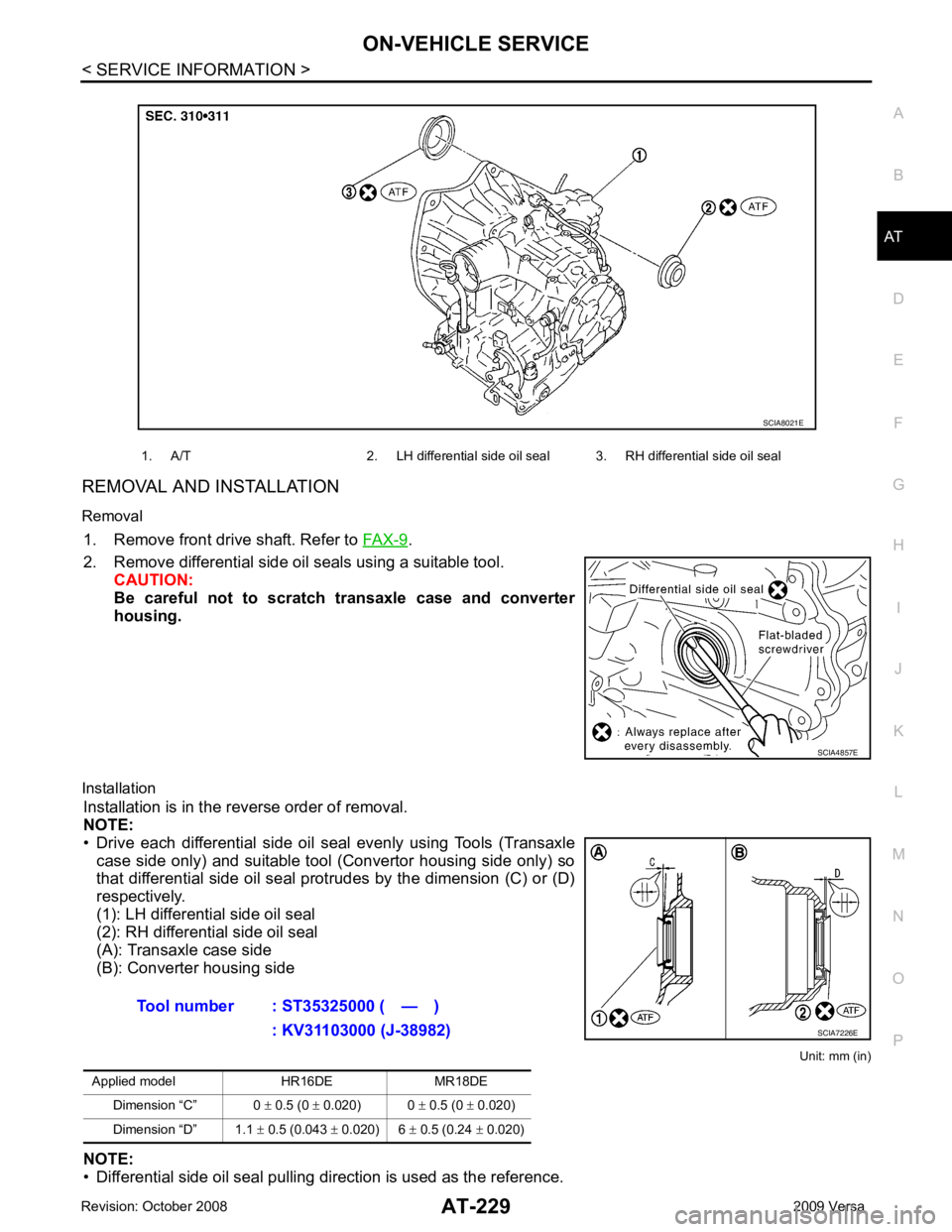
Removal 1. Remove front drive shaft. Refer to FAX-9 .
2. Remove differential side oil seals using a suitable tool. CAUTION:
Be careful not to scratch transaxle case and converter
housing.
Installation Installation is in the reverse order of removal.
NOTE:
• Drive each differential side oil seal evenly using Tools (Transaxle case side only) and suitable tool (Convertor housing side only) so
that differential side oil seal protrudes by the dimension (C) or (D)
respectively.
(1): LH differential side oil seal
(2): RH differential side oil seal
(A): Transaxle case side
(B): Converter housing side
Unit: mm (in)
NOTE:
• Differential side oil seal pulling direction is used as the reference. 1. A/T 2. LH differential side oil seal 3. RH differential side oil seal