2009 NISSAN LATIO ESP
[x] Cancel search: ESPPage 1217 of 4331
CVT
N
O P
DTC P0745 LINE PRESSURE SOLENOID VALVE
Description INFOID:0000000004305682
• The pressure control solenoid valve A (line pressure solenoid valve) is included in the control valve assem- bly.
• The pressure control solenoid valve A (line pressure solenoid valve) regulates the oil pump discharge pres-
sure to suit the driving condition in response to a signal sent from the TCM.
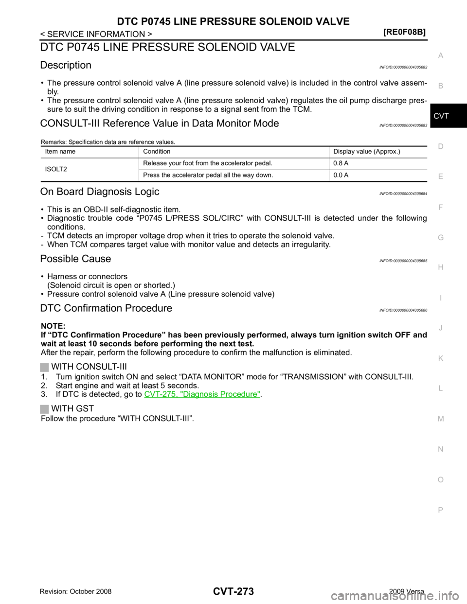
CONSULT-III Reference Val ue in Data Monitor Mode INFOID:0000000004305683
Remarks: Specification data are reference values.
On Board Diagnosis Logic INFOID:0000000004305684
• This is an OBD-II self-diagnostic item.
• Diagnostic trouble code “P0745 L/PRESS SOL/CIRC” with CONSULT-III is detected under the following
conditions.
- TCM detects an improper voltage drop when it tries to operate the solenoid valve.
- When TCM compares target value with monitor value and detects an irregularity.
Possible Cause INFOID:0000000004305685
• Harness or connectors (Solenoid circuit is open or shorted.)
• Pressure control solenoid valve A (Line pressure solenoid valve)
DTC Confirmation Procedure INFOID:0000000004305686
NOTE:
If “DTC Confirmation Procedure” has been previously performed, alw ays turn ignition switch OFF and
wait at least 10 seconds before performing the next test.
After the repair, perform the following procedure to confirm the malfunction is eliminated.
WITH CONSULT-III
1. Turn ignition switch ON and select “DATA MO NITOR” mode for “TRANSMISSION” with CONSULT-III.
2. Start engine and wait at least 5 seconds.
3. If DTC is detected, go to CVT-275, " Diagnosis Procedure " .
WITH GST
Follow the procedure “WITH CONSULT-III”. Item name Condition Display value (Approx.)
ISOLT2 Release your foot from the accelerator pedal. 0.8 A
Press the accelerator pedal all the way down. 0.0 A
Page 1237 of 4331
CVT
N
O P
DTC P0868 SECONDARY PRESSURE DOWN
Description INFOID:0000000004305730
• The pressure control solenoid valve B (secondary pressure solenoid valve) is included in the control valve assembly.
• The pressure control solenoid valve B (secondary pressure solenoid valve) regulates the secondary pres-
sure to suit the driving condition in response to a signal sent from the TCM.
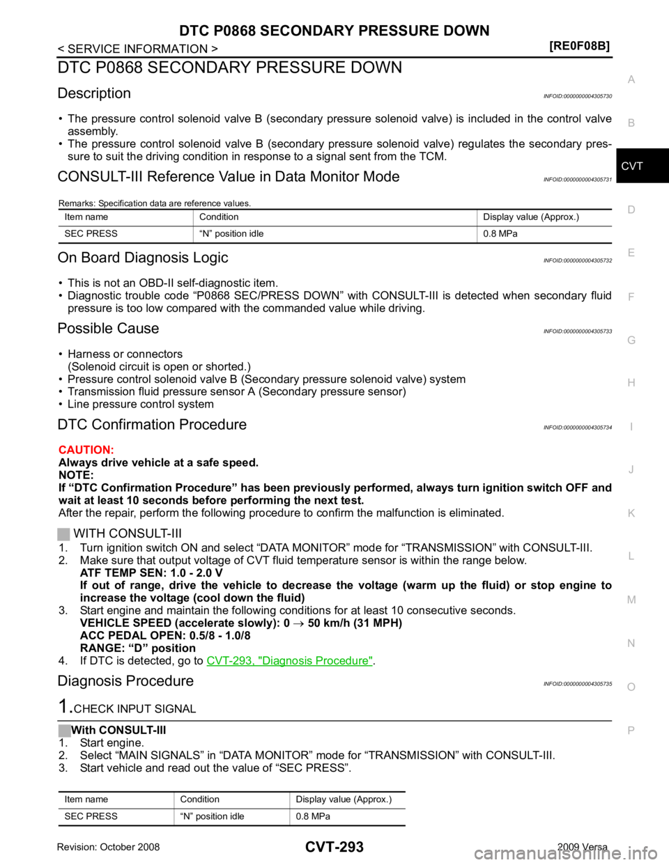
CONSULT-III Reference Val ue in Data Monitor Mode INFOID:0000000004305731
Remarks: Specification data are reference values.
On Board Diagnosis Logic INFOID:0000000004305732
• This is not an OBD-II self-diagnostic item.
• Diagnostic trouble code “P0868 SEC/PRESS DOWN” with CONSULT-III is detected when secondary fluid
pressure is too low compared with the commanded value while driving.
Possible Cause INFOID:0000000004305733
• Harness or connectors (Solenoid circuit is open or shorted.)
• Pressure control solenoid valve B (Secondary pressure solenoid valve) system
• Transmission fluid pressure sensor A (Secondary pressure sensor)
• Line pressure control system
DTC Confirmation Procedure INFOID:0000000004305734
CAUTION:
Always drive vehicle at a safe speed.
NOTE:
If “DTC Confirmation Procedure” has been previously performed, alw ays turn ignition switch OFF and
wait at least 10 seconds before performing the next test.
After the repair, perform the following procedure to confirm the malfunction is eliminated.
WITH CONSULT-III
1. Turn ignition switch ON and select “DATA MO NITOR” mode for “TRANSMISSION” with CONSULT-III.
2. Make sure that output voltage of CVT fluid temperature sensor is within the range below.
ATF TEMP SEN: 1.0 - 2.0 V
If out of range, drive the vehicle to decrease the voltage (warm up the fluid) or stop engine to
increase the voltage (c ool down the fluid)
3. Start engine and maintain the following conditions for at least 10 consecutive seconds. VEHICLE SPEED (accelerate slowly): 0 → 50 km/h (31 MPH)
ACC PEDAL OPEN: 0.5/8 - 1.0/8
RANGE: “D” position
4. If DTC is detected, go to CVT-293, " Diagnosis Procedure " .
Diagnosis Procedure INFOID:0000000004305735
Page 1255 of 4331
CVT
N
O P
DTC P1777 STEP MOTOR - CIRCUIT
Description INFOID:0000000004305777
• The step motor is included in the control valve assembly.
• The step motor changes the step with turning 4 coils ON/OF F according to the signal from TCM. As a result,
the flow of line pressure to primary pu lley is changed and pulley ratio is controlled
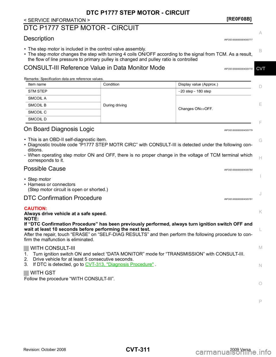
CONSULT-III Reference Val ue in Data Monitor Mode INFOID:0000000004305778
Remarks: Specification data are reference values.
On Board Diagnosis Logic INFOID:0000000004305779
• This is an OBD-II self-diagnostic item.
• Diagnostic trouble code “P1777 STEP MOTR CIRC” with CONSULT-III is detected under the following con-
ditions.
- When operating step motor ON and OFF, there is no proper change in the voltage of TCM terminal which corresponds to it.
Possible Cause INFOID:0000000004305780
• Step motor
• Harness or connectors
(Step motor circuit is open or shorted.)
DTC Confirmation Procedure INFOID:0000000004305781
CAUTION:
Always drive vehicle at a safe speed.
NOTE:
If “DTC Confirmation Procedure” has been previously performed, alw ays turn ignition switch OFF and
wait at least 10 seconds before performing the next test.
After the repair, touch “ERASE” on “SELF-DIAG RESU LTS” and then perform the following procedure to con-
firm the malfunction is eliminated.
WITH CONSULT-III
1. Turn ignition switch ON and select “DATA MO NITOR” mode for “TRANSMISSION” with CONSULT-III.
2. Drive vehicle for at least 5 consecutive seconds.
3. If DTC is detected, go to CVT-313, " Diagnosis Procedure " .
WITH GST
Follow the procedure “WITH CONSULT-III”. Item name Condition Display value (Approx.)
STM STEP
During driving−
20 step - 180 step
SMCOIL A
Changes ON⇔OFF.
SMCOIL B
SMCOIL C
SMCOIL D
Page 1279 of 4331
![NISSAN LATIO 2009 Service Repair Manual CVT SHIFT LOCK SYSTEM
CVT-335
< SERVICE INFORMATION >
[RE0F08B] D
E
F
G H
I
J
K L
M A
B CVT
N
O P
CVT SHIFT LOCK SYSTEM
Description INFOID:0000000004305812
• The mechanical key interlock mechanism a NISSAN LATIO 2009 Service Repair Manual CVT SHIFT LOCK SYSTEM
CVT-335
< SERVICE INFORMATION >
[RE0F08B] D
E
F
G H
I
J
K L
M A
B CVT
N
O P
CVT SHIFT LOCK SYSTEM
Description INFOID:0000000004305812
• The mechanical key interlock mechanism a](/manual-img/5/57359/w960_57359-1278.png)
CVT SHIFT LOCK SYSTEM
CVT-335
< SERVICE INFORMATION >
[RE0F08B] D
E
F
G H
I
J
K L
M A
B CVT
N
O P
CVT SHIFT LOCK SYSTEM
Description INFOID:0000000004305812
• The mechanical key interlock mechanism also operates as a shift lock: With the ignition switch turned to ON, selector lever cannot be shifted from “P” position to any other position
unless brake pedal is depressed.
With the key removed, selector lever cannot be shifted from “P” position to any other position.
The key cannot be removed unless selector lever is placed in “P” position.
• The shift lock and key interlock mechanisms are controlled by the ON-OFF operation of the shift lock sole-
noid and by the operation of the rotator and sli der located inside key cylinder, respectively.
Shift Lock System Electrical Parts Location INFOID:0000000004305813
1. Key interlock cable 2. Key cylinder 3. Stop lamp switch
4. Brake pedal 5. Shift lock release button 6. Key interlock cable
7. Shift lock solenoid 8. Park position switch BCIA0034E
Page 1350 of 4331
CONSULT-III Function (BCM) " .
Self - diagnostic results content
No malfunction detected>>GO TO 2.
Malfunction detected>> Check applicable parts, and repair or replace corresponding parts. CONSULT-III Function (METER/M&A) " .
Self - diagnostic results content
No malfunction detected>> Inspection End.
Malfunction detected>> Check applicable parts, and repair or replace corresponding parts.
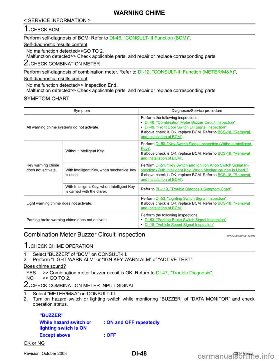
SYMPTOM CHART
Combination Meter Buzzer Circuit Inspection INFOID:0000000004307033YES >> Combination meter buzzer circuit is OK. Return to
DI-47, " Trouble Diagnosis " .
NO >> GO TO 2. Combination Meter Buzzer Circuit Inspection "
•
DI-49, " Front Door Switch LH Signal Inspection "
If above check is OK, replace BCM. Refer to
BCS-18, " Removal
and Installation of BCM " .
Key warning chime
does not activate. Without Intelligent Key.
Perform
DI-50, " Key Switch Signal Inspection (Without Intelligent
Key) " .
If above check is OK, replace BCM. Refer to BCS-18, " Removal
and Installation of BCM " .
With Intelligent Key, when mechanical key
is used. Perform
DI-51, " Key Switch and Ignition Knob Switch Signal In-
spection (With Intelligent Key, When Mechanical Key Is Used) " .
If above check is OK, replace BCM. Refer to BCS-18, " Removal
and Installation of BCM " .
With Intelligent Key, when Intelligent Key
is carried with the driver. Refer to
BL-119, " Trouble Diagnosis Symptom Chart " .
Light warning chime does not activate. Perform
DI-53, " Lighting Switch Signal Inspection " .
If above check is OK, replace BCM. Refer to BCS-18, " Removal
and Installation of BCM " .
Parking brake warning chime does not activate Perform the following inspections
• DI-53, " Parking Brake Switch Signal Inspection "
•
DI-15, " Vehicle Speed Signal Inspection "
Page 1449 of 4331

EC
NP
O
In most cases the ECM will automatically complete its self-diagnosis cycle during normal usage, and the SRT
status will indicate “CMPLT” for each application syste m. Once set as “CMPLT”, the SRT status remains
“CMPLT” until the self-diagnosis memory is erased.
Occasionally, certain portions of the self-diagnostic test may not be completed as a result of the customer's
normal driving pattern; the SRT will indicate “INCMP” for these items.
NOTE:
The SRT will also indicate “INCMP” if the self-diagnosis memory is erased for any reason or if the ECM mem-
ory power supply is interrupted for several hours.
If, during the state emissions inspection, the SRT indica tes “CMPLT” for all test items, the inspector will con-
tinue with the emissions test. However, if the SRT i ndicates “INCMP” for one or more of the SRT items the
vehicle is returned to the customer untested.
NOTE:
If MIL is ON during the state emissi ons inspection, the vehicle is also returned to the customer untested even
though the SRT indicates “CMPLT” for all test items. T herefore, it is important to check SRT (“CMPLT”) and
DTC (No DTCs) before the inspection.
SRT Item The table below shows required self-diagnostic items to set the SRT to “CMPLT”.
*: If completion of several SRTs is required, perform driving patterns (DTC CONFIRMATION PROCEDURE), one by one based on the
priority for models with CONSULT-III.
SRT Set Timing SRT is set as “CMPLT” after self-diagnosis has been performed one or more times. Completion of SRT is
done regardless of whether the result is OK or NG. T he set timing is different between OK and NG results and
is shown in the table below. SRT item
(CONSULT-III indication) Performance
Priority* Required self-diagnostic items to set the SRT to “CMPLT”
Corresponding
DTC No.
CATALYST 2 Three way catalyst function P0420
EVAP SYSTEM 2 EVAP control system purge flow monitoring P0441
1 EVAP control system P0442
2 EVAP control system P0456
HO2S 2 Air fuel ratio (A/F) sensor 1 P0133 Heated oxygen sensor 2 P0137
Heated oxygen sensor 2 P0138
Heated oxygen sensor 2 P0139 Self-diagnosis result
Example
Diagnosis Ignition cycle
← ON →OFF ← ON →OFF ← ON →OFF ← ON →
All OK Case 1 P0400 OK (1) — (1) OK (2) — (2) P0402 OK (1) — (1) — (1) OK (2)
P1402 OK (1) OK (2) — (2) — (2)
SRT of EGR “CMPLT” “CMPLT” “CMPLT” “CMPLT”
Case 2 P0400 OK (1) — (1) — (1) — (1) P0402 — (0) — (0) OK (1) — (1)
P1402 OK (1) OK (2) — (2) — (2)
SRT of EGR “INCMP” “INCMP” “CMPLT” “CMPLT”
Page 1505 of 4331
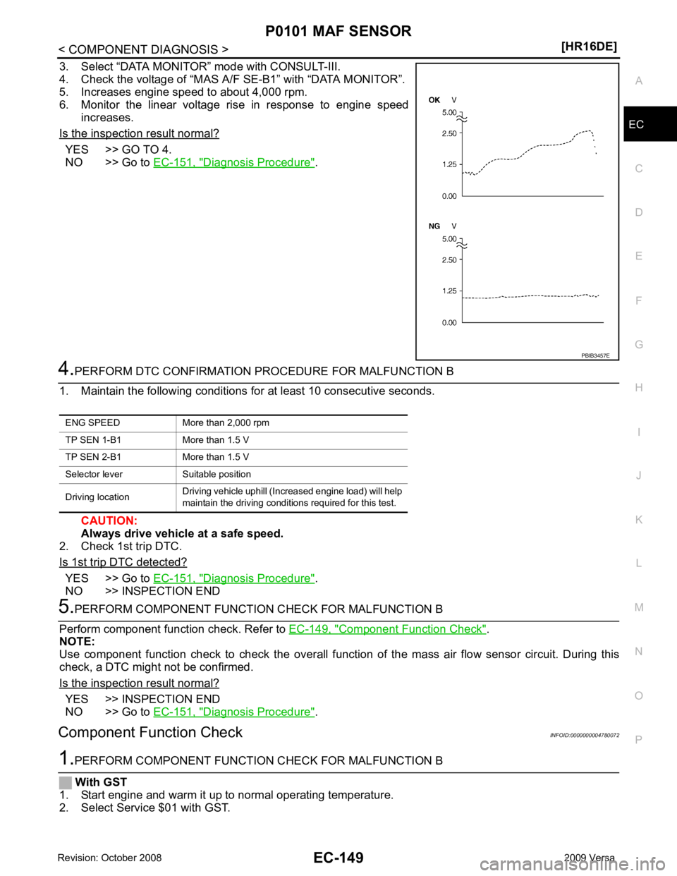
EC
NP
O
3. Select “DATA MONITOR” mode with CONSULT-III.
4. Check the voltage of “MAS A/F SE-B1” with “DATA MONITOR”.
5. Increases engine speed to about 4,000 rpm.
6. Monitor the linear voltage rise in response to engine speed
increases.
Is the inspection result normal? YES >> GO TO 4.
NO >> Go to EC-151, " Diagnosis Procedure " .
YES >> Go to
EC-151, " Diagnosis Procedure " .
NO >> INSPECTION END Component Function Check " .
NOTE:
Use component function check to check the overall function of the mass air flow sensor circuit. During this
check, a DTC might not be confirmed.
Is the inspection result normal? YES >> INSPECTION END
NO >> Go to EC-151, " Diagnosis Procedure " .
Component Function Check INFOID:0000000004780072
Page 1511 of 4331
![NISSAN LATIO 2009 Service Repair Manual P0101 MAF SENSOR
EC-155
< COMPONENT DIAGNOSIS >
[HR16DE] C
D E
F
G H
I
J
K L
M A EC
NP
O
3. Check the voltage between ECM harness connector and
ground.
*: Check for linear voltage rise in respo NISSAN LATIO 2009 Service Repair Manual P0101 MAF SENSOR
EC-155
< COMPONENT DIAGNOSIS >
[HR16DE] C
D E
F
G H
I
J
K L
M A EC
NP
O
3. Check the voltage between ECM harness connector and
ground.
*: Check for linear voltage rise in respo](/manual-img/5/57359/w960_57359-1510.png)
P0101 MAF SENSOR
EC-155
< COMPONENT DIAGNOSIS >
[HR16DE] C
D E
F
G H
I
J
K L
M A EC
NP
O
3. Check the voltage between ECM harness connector and
ground.
*: Check for linear voltage rise in response to engine being increased to about 4,000 rpm.
Is the inspection result normal? YES >> INSPECTION END
NO >> GO TO 4. 4.
CHECK MASS AIR FLOW SENSOR-III
With CONSULT-III
1. Turn ignition switch OFF.
2. Disconnect mass air flow sensor har ness connector and reconnect it again.
3. Start engine and warm it up to normal operating temperature.
4. Connect CONSULT-III and select “DATA MONITOR” mode.
5. Select “MAS A/F SE-B1” and check indication.
*: Check for linear voltage rise in response to engine being increased to about 4,000 rpm.
Without CONSULT-III
1. Turn ignition switch OFF.
2. Disconnect mass air flow sensor har ness connector and reconnect it again.
3. Start engine and warm it up to normal operating temperature.
4. Check the voltage between ECM harness connector and ground.
*: Check for linear voltage rise in response to engine being increased to about 4,000 rpm.
Is the inspection result normal? YES >> INSPECTION END
NO >> Clean or replace mass air flow sensor. ECM
Ground Condition Voltage
Con-
nector Termi-
nal
F11 45
(MAF
sensor
signal) Ground Ignition switch ON (Engine stopped.) Approx. 0.4 V
Idle (Engine is wa rmed-up to normal
operating temperature.) 0.9 - 1.3 V
2,500 rpm (Engine is warmed-up to
normal operating temperature.) 1.4 - 1.9 V
Idle to about 4,000 rpm 0.9 - 1.3 V to
Approx. 2.4 V* PBIA9564J
Monitor item Condition MAS A/F SE-B1
MAS A/F SE-B1 Ignition switch ON (Engine stopped.) Approx. 0.4 V
Idle (Engine is warmed-up to normal operating temperature.) 0.9 - 1.3 V
2,500 rpm (Engine is warmed-up to normal operating temperature.) 1.4 - 1.9 V
Idle to about 4,000 rpm 0.9 - 1.3 V to Approx. 2.4 V*
ECM Ground Condition Voltage
Con-
nector Termi-
nal
F11 45
(MAF
sensor
signal) Ground Ignition switch ON (Engine stopped.) Approx. 0.4 V
Idle (Engine is wa rmed-up to normal
operating temperature.) 0.9 - 1.3 V
2,500 rpm (Engine is warmed-up to
normal operating temperature.) 1.4 - 1.9 V
Idle to about 4,000 rpm 0.9 - 1.3 V to
Approx. 2.4 V* PBIA9564J