2009 NISSAN LATIO ESP
[x] Cancel search: ESPPage 348 of 4331
AT
N
O P
ASSEMBLY
Assembly (1) INFOID:0000000004305528
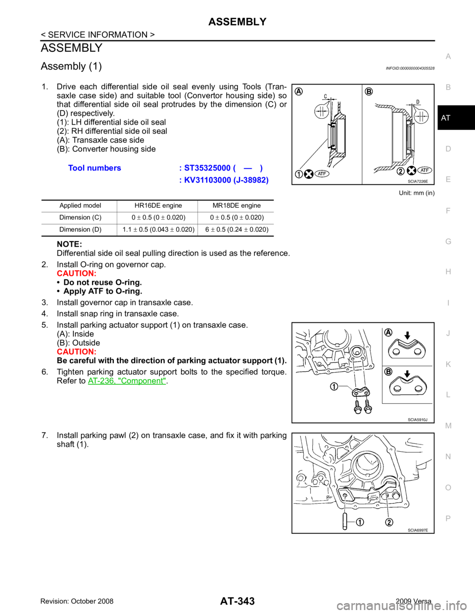
1. Drive each differential side oil seal evenly using Tools (Tran- saxle case side) and suitable tool (Convertor housing side) so
that differential side oil seal protrudes by the dimension (C) or
(D) respectively.
(1): LH differential side oil seal
(2): RH differential side oil seal
(A): Transaxle case side
(B): Converter housing side
Unit: mm (in)
NOTE:
Differential side oil seal pulling direction is used as the reference.
2. Install O-ring on governor cap. CAUTION:
• Do not reuse O-ring.
• Apply ATF to O-ring.
3. Install governor cap in transaxle case.
4. Install snap ring in transaxle case.
5. Install parking actuator support (1) on transaxle case. (A): Inside
(B): Outside
CAUTION:
Be careful with the direction of parking actuator support (1).
6. Tighten parking actuator support bolts to the specified torque. Refer to AT-236, " Component " .
7. Install parking pawl (2) on transaxle case, and fix it with parking shaft (1).Tool numbers : ST35325000 ( — )
: KV31103000 (J-38982)
Applied model HR16DE engine MR18DE engine
Dimension (C) 0 ± 0.5 (0 ± 0.020) 0 ± 0.5 (0 ± 0.020)
Dimension (D) 1.1 ± 0.5 (0.043 ± 0.020) 6 ± 0.5 (0.24 ± 0.020)
Page 445 of 4331
BCS
N
O P
BCM (BODY CONTROL MODULE)
System Description INFOID:0000000004306833
BCM (body control module) controls the operation of various electrical units installed on the vehicle.
BCM FUNCTION BCM has a combination switch reading function for reading the operation of combination switches (light, wiper,
washer, turn signal) in addition to the function for c ontrolling the operation of various electrical components.
Also, it functions as an interface that receives signal s from the front air control, and sends signals to ECM
using CAN communication.
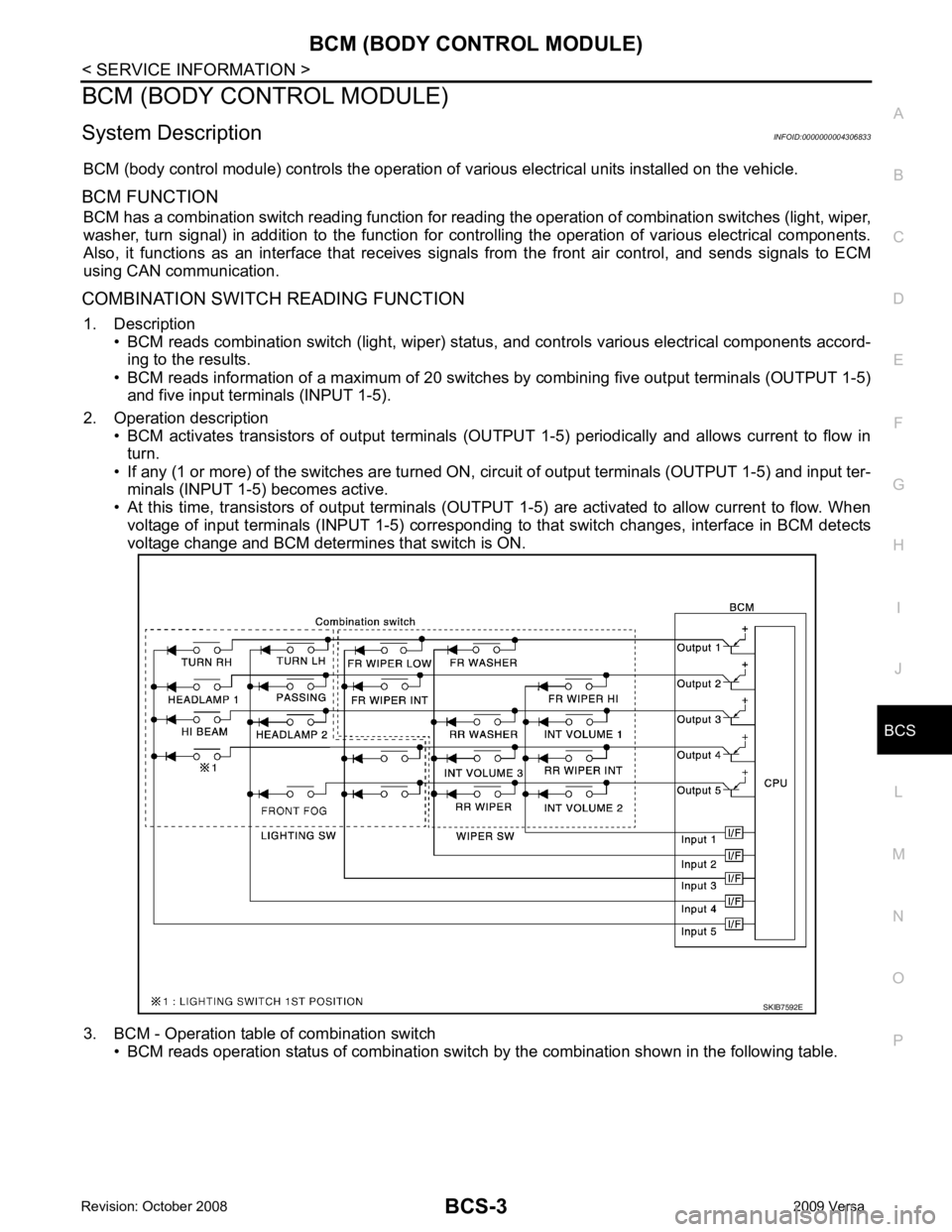
COMBINATION SWITCH READING FUNCTION 1. Description • BCM reads combination switch (light, wiper) status , and controls various electrical components accord-
ing to the results.
• BCM reads information of a maximum of 20 switches by combining five output terminals (OUTPUT 1-5)
and five input terminals (INPUT 1-5).
2. Operation description • BCM activates transistors of output terminals (OUTPUT 1-5) periodically and allows current to flow in
turn.
• If any (1 or more) of the switches are turned ON, circuit of output terminals (OUTPUT 1-5) and input ter-
minals (INPUT 1-5) becomes active.
• At this time, transistors of output terminals (OUTPUT 1-5) are activated to allow current to flow. When
voltage of input terminals (INPUT 1-5) corresponding to that switch changes, interface in BCM detects
voltage change and BCM determines that switch is ON.
3. BCM - Operation table of combination switch • BCM reads operation status of combination switch by the combination shown in the following table.
Page 468 of 4331
BL
N
O P
SQUEAK AND RATTLE TROUBLE DIAGNOSES
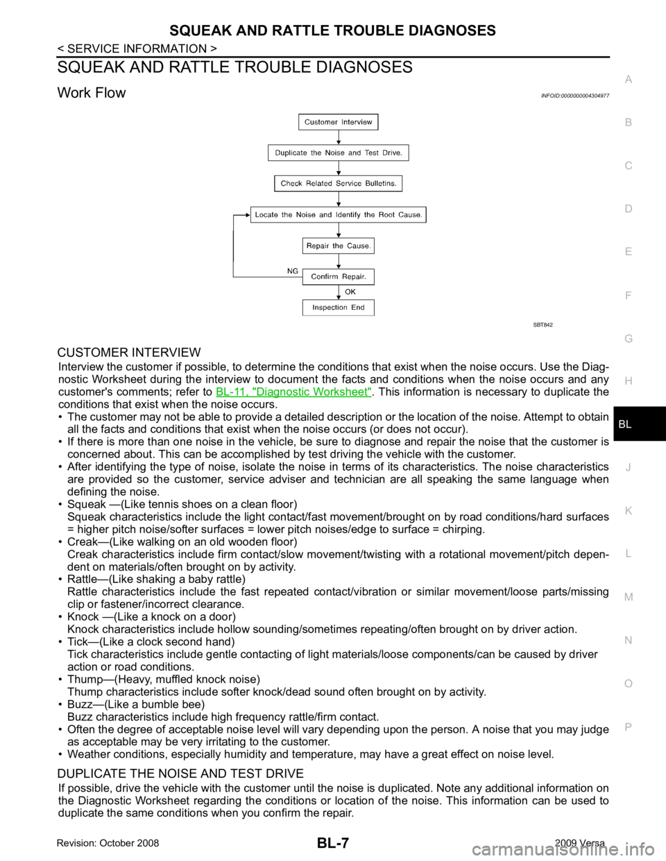
Work Flow INFOID:0000000004304977
CUSTOMER INTERVIEW Interview the customer if possible, to determine the c onditions that exist when the noise occurs. Use the Diag-
nostic Worksheet during the interv iew to document the facts and conditions when the noise occurs and any
customer's comments; refer to BL-11, " Diagnostic Worksheet " . This information is necessary to duplicate the
conditions that exist when the noise occurs.
• The customer may not be able to provide a detailed descr iption or the location of the noise. Attempt to obtain
all the facts and conditions that exist when the noise occurs (or does not occur).
• If there is more than one noise in the vehicle, be sure to diagnose and repair the noise that the customer is
concerned about. This can be accomplished by test driving the vehicle with the customer.
• After identifying the type of noise, isolate the noise in terms of its characteristics. The noise characteristics
are provided so the customer, service adviser and technician are all speaking the same language when
defining the noise.
• Squeak —(Like tennis shoes on a clean floor)
Squeak characteristics include the light contact/fast movement/brought on by road conditions/hard surfaces
= higher pitch noise/softer surfaces = lower pitch noises/edge to surface = chirping.
• Creak—(Like walking on an old wooden floor)
Creak characteristics include firm contact/slow mo vement/twisting with a rotational movement/pitch depen-
dent on materials/often brought on by activity.
• Rattle—(Like shaking a baby rattle)
Rattle characteristics include the fast repeated contac t/vibration or similar movement/loose parts/missing
clip or fastener/incorrect clearance.
• Knock —(Like a knock on a door)
Knock characteristics include hollow sounding/someti mes repeating/often brought on by driver action.
• Tick—(Like a clock second hand) Tick characteristics include gentle contacting of li ght materials/loose components/can be caused by driver
action or road conditions.
• Thump—(Heavy, muffled knock noise) Thump characteristics include softer k nock/dead sound often brought on by activity.
• Buzz—(Like a bumble bee)
Buzz characteristics include high frequency rattle/firm contact.
• Often the degree of acceptable noise level will vary depending upon the person. A noise that you may judge as acceptable may be very irritating to the customer.
• Weather conditions, especially humidity and temperature, may have a great effect on noise level.
DUPLICATE THE NOISE AND TEST DRIVE If possible, drive the vehicle with the customer until the noise is duplicated. Note any additional information on
the Diagnostic Worksheet regarding the conditions or lo cation of the noise. This information can be used to
duplicate the same conditions when you confirm the repair.
Page 534 of 4331
BL
N
O P
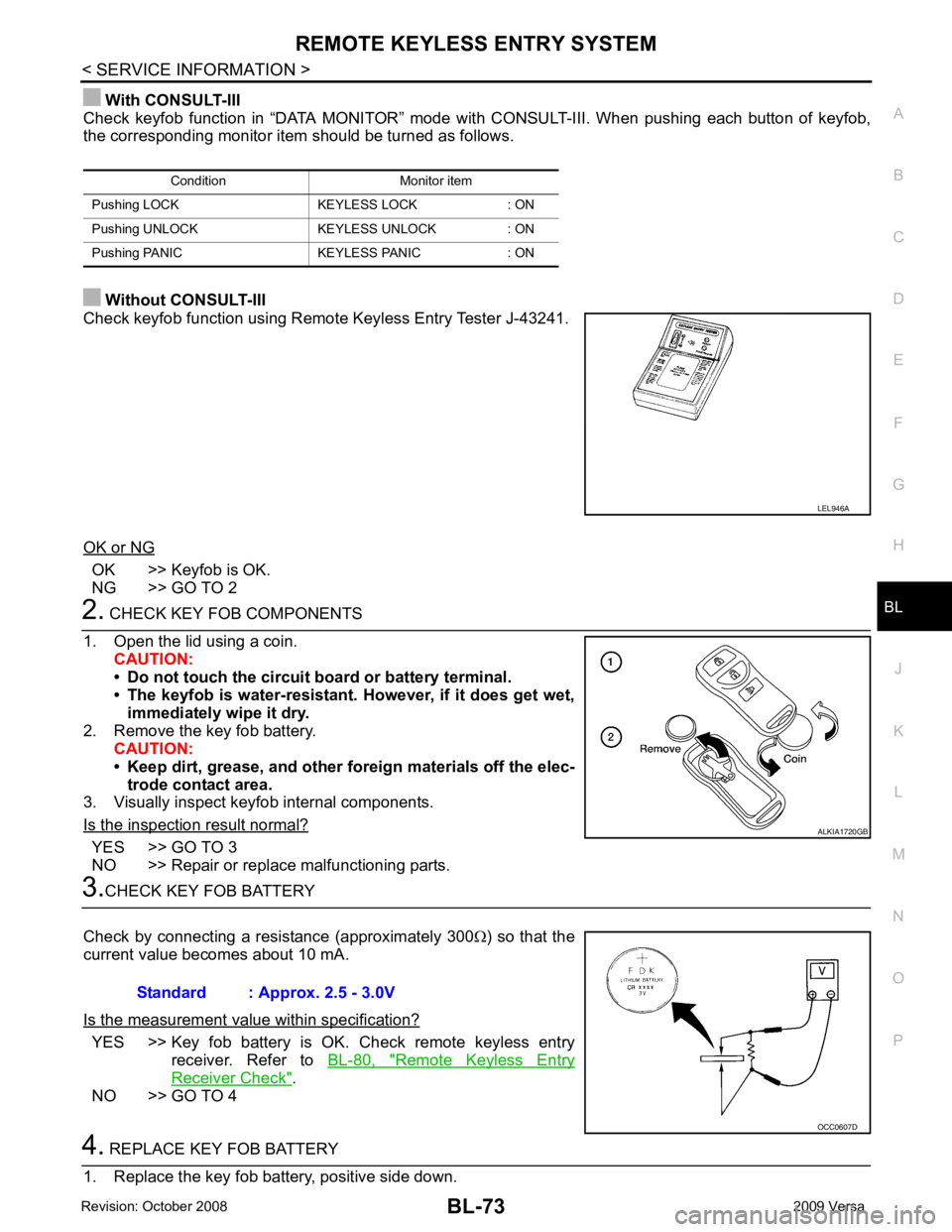
With CONSULT-III
Check keyfob function in “DATA MONITOR” mode wit h CONSULT-III. When pushing each button of keyfob,
the corresponding monitor item should be turned as follows.
Without CONSULT-III
Check keyfob function using Remote Keyless Entry Tester J-43241.
OK or NG OK >> Keyfob is OK.
NG >> GO TO 2 YES >> GO TO 3
NO >> Repair or replace malfunctioning parts. YES >> Key fob battery is OK. Check remote keyless entry
receiver. Refer to BL-80, " Remote Keyless Entry
Receiver Check " .
NO >> GO TO 4
Page 550 of 4331
BL
N
O P
Operation Description
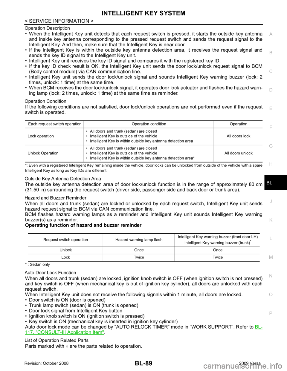
• When the Intelligent Key unit detects that each request sw itch is pressed, it starts the outside key antenna
and inside key antenna corresponding to the pressed r equest switch and sends the request signal to the
Intelligent Key. And then, make sure that the Intelligent Key is near door.
• If the Intelligent Key is within the outside key ant enna detection area, it receives the request signal and
sends the key ID signal to the Intelligent Key unit.
• Intelligent Key unit receives the key ID signal and compares it with the registered key ID.
• If the key ID check result is OK, the Intelligent Ke y unit sends the door lock/unlock request signal to BCM
(Body control module) via CAN communication line.
• Intelligent Key unit sends the door lock/unlock signal and sounds Intelligent Key warning buzzer (lock: 2 times, unlock: 1 time) at the same time.
• When BCM receives the door lock/unlock signal, it oper ates door lock actuator and flashes the hazard warn-
ing lamp (lock: 2 times, unlock: 1 time) at the same time as reminder.
Operation Condition If the following conditions are not satisfied, door lo ck/unlock operations are not performed even if the request
switch is operated.
*: Even with a registered Intelligent Key remaining inside the vehicle, door locks can be unlocked from outside of the vehicle with a spare
Intelligent Key as long as Key IDs are different.
Outside Key Antenna Detection Area The outside key antenna detection area of door lock/unloc k function is in the range of approximately 80 cm
(31.50 in) surrounding the request switch (driver side, passenger side and back door or trunk area).
Hazard and Buzzer Reminder When all doors and trunk (sedan) are locked or unlocked by each request switch, Intelligent Key unit sends
hazard request signal to BCM via CAN communication line.
BCM flashes hazard warning lamps as a reminder and Intelligent Key unit sounds Intelligent Key warning
buzzer(s) as a reminder.
Operating function of hazard and buzzer reminder
* : Sedan only
Auto Door Lock Function When all doors and trunk (sedan) are locked, ignition knob sw itch is OFF (when ignition switch is not pressed)
and key switch is OFF (when mechanical key is out of ignition key cylinder), all doors are unlocked with each
request switch.
When Intelligent Key unit does not receive the following signals within 1 minute, all doors are locked.
• Door switch is ON (door is opened)
• Trunk lamp switch (sedan) is ON (trunk is opened)
• Door lock signal from Intelligent Key button
• Ignition knob switch is ON (ignition switch is pressed)
• Key switch is ON (mechanical key is inserted in ignition key cylinder)
Auto door lock mode can be changed by “AUTO RELOCK TIMER” mode in “WORK SUPPORT”. Refer to BL-117, " CONSULT-III Application Item " .
List of Operation Related Parts Parts marked with × are the parts related to operation.
Each request switch operation Operation condition Operation
Lock operation • All doors and trunk (sedan) are closed
• Intelligent Key is outside of the vehicle
• Intelligent Key is within outside key antenna detection area All doors lock
Unlock Operation • All doors and trunk (sedan) are closed
• Intelligent Key is outside of the vehicle
• Intelligent Key is within outside key antenna detection area* All doors unlockRequest switch operation Hazard warning lamp flash
Intelligent Key warning buzzer (front door LH)
Intelligent Key warning buzzer (trunk) *
Unlock Once Once Lock Twice Twice
Page 959 of 4331
![NISSAN LATIO 2009 Service Repair Manual PRECAUTIONS
CVT-15
< SERVICE INFORMATION >
[RE0F08A] D
E
F
G H
I
J
K L
M A
B CVT
N
O P
•
Before replacing TCM, perform TCM input/output signal
inspection and make sure whether TCM functions pr NISSAN LATIO 2009 Service Repair Manual PRECAUTIONS
CVT-15
< SERVICE INFORMATION >
[RE0F08A] D
E
F
G H
I
J
K L
M A
B CVT
N
O P
•
Before replacing TCM, perform TCM input/output signal
inspection and make sure whether TCM functions pr](/manual-img/5/57359/w960_57359-958.png)
PRECAUTIONS
CVT-15
< SERVICE INFORMATION >
[RE0F08A] D
E
F
G H
I
J
K L
M A
B CVT
N
O P
•
Before replacing TCM, perform TCM input/output signal
inspection and make sure whether TCM functions properly or
not. CVT-49, " TCM Terminal and Reference Value " .
• After performing each TROUBL E DIAGNOSIS, perform “DTC
Confirmation Procedure”.
If the repair is completed the DTC should not be displayed in
the “DTC Confirmation Procedure”.
• Always use the specified br and of CVT fluid. Refer to MA-14, " Flu-
ids and Lubricants " .
• Use lint-free paper, not cloth rags, during work.
• After replacing the CVT fluid, dispose of the waste oil using the methods prescribed by law, ordinance, etc.
Service Notice or Precaution INFOID:0000000004666859
CVT FLUID COOLER SERVICE If CVT fluid contains friction material (clutches, brakes , etc.), or if an CVT is replaced, inspect and clean the
CVT fluid cooler mounted in the radiator or replace t he radiator. Flush cooler lines using cleaning solvent and
compressed air after repair. For CVT fluid cooler cleaning procedure, refer to CVT-18, " CVT Fluid Cooler
Cleaning " . For radiator replacement, refer to
CO-38 .
OBD-II SELF-DIAGNOSIS • CVT self-diagnosis is performed by the TCM in comb ination with the ECM. The results can be read through
the blinking pattern of the malfunction indi cator lamp (MIL). Refer to the table on CVT-51, " CONSULT-III
Function (TRANSMISSION) " for the indicator used to display each self-diagnostic result.
• The self-diagnostic results indicated by the MIL ar e automatically stored in both the ECM and TCM memo-
ries.
Always perform the procedure on CVT-30, " OBD-II Diagnostic Trouble Code (DTC) " to complete the
repair and avoid unnecessary blinking of the MIL.
For details of OBD-II, refer to EC-541, " Introduction " .
• Certain systems and components, especially those re lated to OBD, may use the new style slide-lock-
ing type harness connector. For descripti on and how to disconnect, refer to PG-64 . MEF040DA
SEF217U
Page 974 of 4331
" CONSULT-III Function (TRANSMISSION) " .
OBD-II Function for CVT System INFOID:0000000004666876
The ECM provides emission-related on board diagnostic (O BD-II) functions for the CVT system. One function
is to receive a signal from the TCM used with OBD-relat ed parts of the CVT system. The signal is sent to the
ECM when a malfunction occurs in the corresponding OBD-re lated part. The other function is to indicate a
diagnostic result by means of the MIL (malfunction indi cator lamp) on the instrument panel. Sensors, switches
and solenoid valves are used as sensing elements.
The MIL automatically illuminates in One or Two Trip Detection Logic when a malfunction is sensed in relation
to CVT system parts.
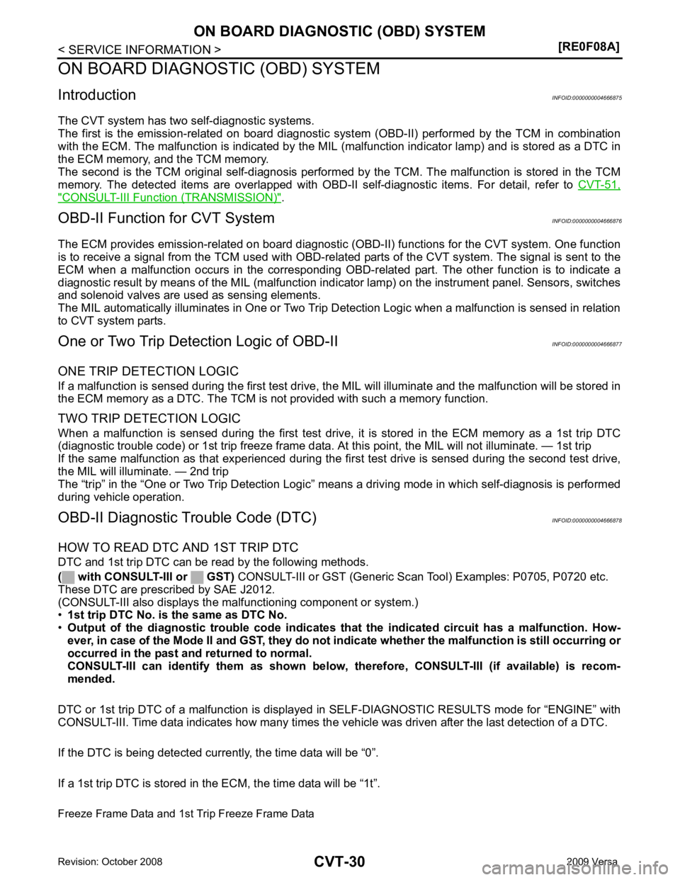
One or Two Trip Detection Logic of OBD-II INFOID:0000000004666877
ONE TRIP DETECTION LOGIC
If a malfunction is sensed during the first test drive, the MIL will illuminate and the malfunction will be stored in
the ECM memory as a DTC. The TCM is not provided with such a memory function.
TWO TRIP DETECTION LOGIC
When a malfunction is sensed during the first test drive, it is stored in the ECM memory as a 1st trip DTC
(diagnostic trouble code) or 1st trip freeze frame data. At this point, the MIL will not illuminate. — 1st trip
If the same malfunction as that experienced during the fi rst test drive is sensed during the second test drive,
the MIL will illuminate. — 2nd trip
The “trip” in the “One or Two Trip Detection Logic” means a driving mode in which self-diagnosis is performed
during vehicle operation.
OBD-II Diagnostic Trouble Code (DTC) INFOID:0000000004666878
HOW TO READ DTC AND 1ST TRIP DTC
DTC and 1st trip DTC can be read by the following methods.
( with CONSULT-III or GST) CONSULT-III or GST (Generic Scan Tool) Examples: P0705, P0720 etc.
These DTC are prescribed by SAE J2012.
(CONSULT-III also displays the malfunctioning component or system.)
• 1st trip DTC No. is the same as DTC No.
• Output of the diagnostic troubl e code indicates that the indicated circuit has a malfunction. How-
ever, in case of the Mode II and GST, they do not indicate whether the malfunction is still occurring or
occurred in the past and returned to normal.
CONSULT-III can identify them as shown below, therefore, CONSULT-III (if available) is recom-
mended.
DTC or 1st trip DTC of a malfunction is displayed in SELF-DIAGNOSTIC RESULTS mode for “ENGINE” with
CONSULT-III. Time data indicates how many times the vehicle was driven after the last detection of a DTC.
If the DTC is being detected currently, the time data will be “0”.
If a 1st trip DTC is stored in the ECM, the time data will be “1t”. Freeze Frame Data and 1st Trip Freeze Frame Data
Page 978 of 4331
![NISSAN LATIO 2009 Service Repair Manual CVT-34< SERVICE INFORMATION >
[RE0F08A]
TROUBLE DIAGNOSIS
If an unexpected signal is sent from the solenoid to t he TCM, the CVT lock-up select solenoid is turned OFF to
cancel the lock-up.
TCM Power NISSAN LATIO 2009 Service Repair Manual CVT-34< SERVICE INFORMATION >
[RE0F08A]
TROUBLE DIAGNOSIS
If an unexpected signal is sent from the solenoid to t he TCM, the CVT lock-up select solenoid is turned OFF to
cancel the lock-up.
TCM Power](/manual-img/5/57359/w960_57359-977.png)
CVT-34< SERVICE INFORMATION >
[RE0F08A]
TROUBLE DIAGNOSIS
If an unexpected signal is sent from the solenoid to t he TCM, the CVT lock-up select solenoid is turned OFF to
cancel the lock-up.
TCM Power Supply (Memory Back-up)
Transaxle assembly is protected by limiting the engine torque when the memory back-up power supply (for
controlling) from the battery is not supplied to TCM. Normal statues is restored when turning the ignition switch
OFF to ON after the normal power supply.
How to Perform Trouble Diagnosis for Quick and Accurate Repair INFOID:0000000004666882
INTRODUCTION
The TCM receives a signal from the vehicle speed sensor, PNP switch and provides shift control or lock-up
control via CVT solenoid valves.
The TCM also communicates with the ECM by means of a signal
sent from sensing elements used wit h the OBD-related parts of the
CVT system for malfunction-diagnostic purposes. The TCM is capa-
ble of diagnosing malfunctioning parts while the ECM can store mal-
functions in its memory.
Input and output signals must always be correct and stable in the
operation of the CVT system. The CVT system must be in good
operating condition and be free of valve seizure, solenoid valve mal-
function, etc.
It is much more difficult to diagnose an error that occurs intermit-
tently rather than continuously. Mo st intermittent errors are caused
by poor electric connections or improper wiring. In this case, careful
checking of suspected circuits ma y help prevent the replacement of
good parts.
A visual check only may not find the cause of the errors. A road test
with CONSULT-III (or GST) or a circuit tester connected should be
performed. Follow the "WORK FLOW" .
Before undertaking actual checks, take a few minutes to talk with a
customer who approaches with a driveability complaint. The cus-
tomer can supply good information about such errors, especially
intermittent ones. Find out what symptoms are present and under
what conditions they occur. A “DIAGNOSTIC WORKSHEET” as
shown on the example (Refer to "Diagnostic Worksheet Chart" )
should be used.
Start your diagnosis by looking for “conventional” errors first. This will
help troubleshoot driveability errors on an electronically controlled
engine vehicle.
Also check related Service bulletins.
WORK FLOW
A good understanding of the malfunction conditions can make troubleshooting faster and more accurate.
In general, each customer feels differently about a malf unction. It is important to fully understand the symp-
toms or conditions for a customer complaint.
Make good use of the two sheets provided, "Informati on From Customer" and "Diagnostic Worksheet Chart" ,
to perform the best troubleshooting possible.
Work Flow Chart SAT631IB
SAT632I
SEF234G