2009 NISSAN LATIO width
[x] Cancel search: widthPage 301 of 4331
AT-296< SERVICE INFORMATION >
REPAIR FOR COMPONENT PARTS
Install control valves.
For installation procedures, refer to AT-289, " Control Valve Upper
Body " .
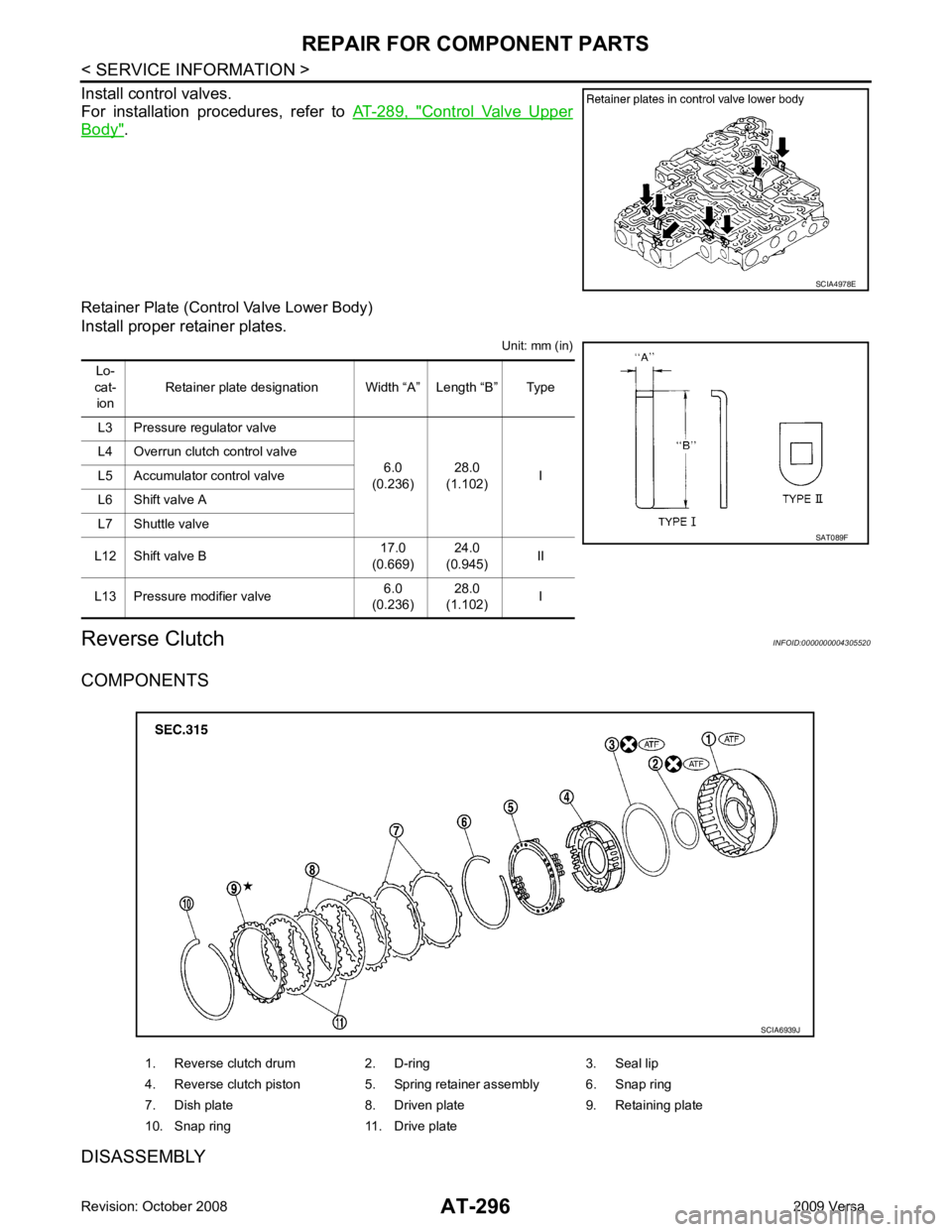
Retainer Plate (Control Valve Lower Body)
Install proper retainer plates. Unit: mm (in)
Reverse Clutch INFOID:0000000004305520
COMPONENTS
DISASSEMBLY SCIA4978E
Lo-
cat- ion Retainer plate designation Width “A” Length “B” Type
L3 Pressure regulator valve 6.0
(0.236) 28.0
(1.102) I
L4 Overrun clutch control valve
L5 Accumulator control valve
L6 Shift valve A
L7 Shuttle valve
L12 Shift valve B 17.0
(0.669) 24.0
(0.945) II
L13 Pressure modifier valve 6.0
(0.236) 28.0
(1.102) I SAT089F
1. Reverse clutch drum 2. D-ring 3. Seal lip
4. Reverse clutch piston 5. Spring retainer assembly 6. Snap ring
7. Dish plate 8. Driven plate 9. Retaining plate
10. Snap ring 11. Drive plate SCIA6939J
Page 382 of 4331

AT
N
O P
Final Drive
INFOID:0000000004807941
DIFFERENTIAL SIDE GEAR CLEARANCE
DIFFERENTIAL SIDE BEARING END PL AY (FOR HR16DE ENGINE MODELS)
BEARING PRELOAD (FOR MR18DE ENGINE MODELS)
TURNING TORQUE (FOR MR18DE ENGINE MODELS)
Planetary Carrier INFOID:0000000004305543
Oil Pump INFOID:0000000004305544
Input Shaft INFOID:0000000004305545
SEAL RING CLEARANCE
SEAL RING Unit: mm (in)
Reduction Pinion Gear INFOID:0000000004305546
TURNING TORQUE
Band Servo INFOID:0000000004305547
RETURN SPRINGS Clearance between side gear and differential case with washer [mm (in)] 0.1 - 0.2 (0.004 - 0.008) Differential side bearing end play mm (in) 0 - 0.15 (0 - 0.0059)
Differential side bearing preload mm (in) 0.05 - 0.09 (0.0020 - 0.0035)
Turning torque of final drive assembly N-m (kg-cm, in-lb) 0.68 - 1.26 (7.0 - 13.0, 6.0 - 11.0)
Clearance between planetary carrier and pinion washer [mm (in)]
Standard 0.15 - 0.70 (0.0059 - 0.0276)
Allowable limit 0.80 (0.0315) Oil pump side clearance
0.02 - 0.04 (0.0008 - 0.0016)
Clearance between oil pump housing and outer gear [mm (in)] Standard 0.08 - 0.15 (0.0031 - 0.0059)
Allowable limit 0.15 (0.0059)
Oil pump cover seal ring clearance [mm (in)] Standard 0.10 - 0.25 (0.0039 - 0.0098)
Allowable limit 0.25 (0.0098) Input shaft seal ring clearance [mm (in)]
Standard 0.08 - 0.23 (0.0031 - 0.0091)
Allowable limit 0.23 (0.091) Outer diameter Inner diameter Width
24 (0.94) 20.4 (0.803) 1.97 (0.0776) Turning torque of reduction pinion gear [N·m (kg-m, in-lb)] 0.11 - 0.69 (0.01 - 0.07, 1 - 6)
Page 383 of 4331
![NISSAN LATIO 2009 Service Repair Manual Output shaft seal ring clearance [mm (in)]
Standard 0.10 - 0.25 (0.0039 - 0.0098)
Allowable limit 0.25 (0.0098) Outer diameter Inner diameter Width
29.5 (1.161) 26.2 (1.031) 1.95 (0.0768) Turning torq NISSAN LATIO 2009 Service Repair Manual Output shaft seal ring clearance [mm (in)]
Standard 0.10 - 0.25 (0.0039 - 0.0098)
Allowable limit 0.25 (0.0098) Outer diameter Inner diameter Width
29.5 (1.161) 26.2 (1.031) 1.95 (0.0768) Turning torq](/manual-img/5/57359/w960_57359-382.png)
Output shaft seal ring clearance [mm (in)]
Standard 0.10 - 0.25 (0.0039 - 0.0098)
Allowable limit 0.25 (0.0098) Outer diameter Inner diameter Width
29.5 (1.161) 26.2 (1.031) 1.95 (0.0768) Turning torque of output shaft ·m (kg-m, in-lb) 0.25 - 0.88 (0.03 - 0.08, 3 - 7)
Output shaft end play mm (in) 0 - 0.5 (0 - 0.020)
Bearing retainer seal ring clearance [mm (in)]
Standard 0.10 - 0.27 (0.0039 - 0.0106)
Allowable limit 0.27 (0.0106) Total end play [mm (in)] 0.25 - 0.55 (0.0098 - 0.0217)
Reverse clutch end play [mm (in)] 0.65 - 1.0 (0.0256 - 0.039)
Engine
HR16DE MR18DE
Distance between end of converter housing and torque converter [mm (in)] 16.2 (0.638) 14.4 (0.567) Gear position 1 2 3 4
Shift solenoid valve A ON (Closed) OFF (Open) OFF (Open) ON (Closed)
Shift solenoid valve B ON (Closed) ON (Closed) OFF (Open) OFF (Open)
Page 838 of 4331

Front brake Brake model CLZ25VF
Cylinder bore diameter 57.2 mm (2.252 in)
Pad
Length × width × thickness 125.6 mm
× 48.0 mm × 9.5 mm
(4.945 in × 1.890 in × 0.374 in)
Rotor outer diameter × thickness 280 mm × 24.0 mm (11.02 in × 0.945 in)
Rear brake Brake model LT23 Cylinder bore diameter 19.06 mm (0.750 in)
Drum inner diameter 228.6 mm (9.000 in)
Master cylinder Cylinder bore diameter 23.81 ± 0.015 mm (0.937 ± 0.001 in)
Brake booster Booster model C255 Diaphragm diameter 255 mm (10.04 in)
Recommended brake fluid DOT 3
Page 1003 of 4331
CVT
N
O P
Diagnosis Procedure
without CONSULT-III INFOID:0000000004666893
OBD-II SELF-DIAGNOSTIC PROCEDURE (WITH GST)
Refer to EC-612, " Generic Scan Tool (GST) Function " .
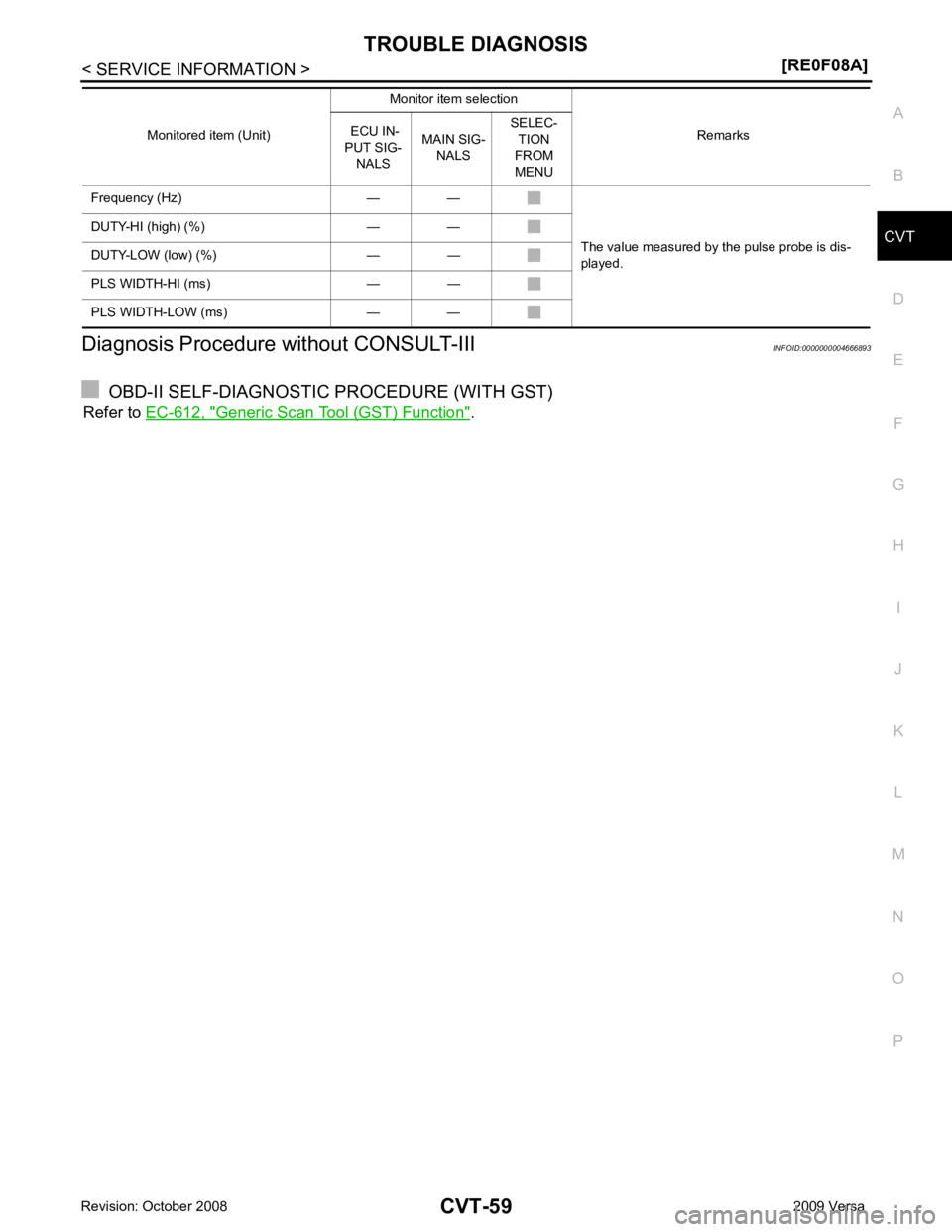
Frequency (Hz) — —
The value measured by the pulse probe is dis-
played.
DUTY-HI (high) (%) — —
DUTY-LOW (low) (%) — —
PLS WIDTH-HI (ms) — —
PLS WIDTH-LOW (ms) — — Monitored item (Unit)
Monitor item selection
Remarks
ECU IN-
PUT SIG- NALS MAIN SIG-
NALS SELEC-
TION
FROM
MENU
Page 1035 of 4331
CVT
N
O P
DTC P0730 BELT DAMAGE
Description INFOID:0000000004666954
TCM selects the gear ratio using the engine load (throttle position), the primary pulley revolution speed, and
the secondary pulley revolution speed as input signal. T hen it changes the operating pressure of the primary
pulley and the secondary pulley and changes the groove width of the pulley.
CONSULT-III Reference Val ue in Data Monitor Mode INFOID:0000000004666955
Remarks: Specification data are reference values.
On Board Diagnosis Logic INFOID:0000000004666956
• This is not an OBD-II self-diagnostic item.
• TCM calculates the actual gear ratio with input speed sensor (primary speed sensor) and output speed sen-
sor (secondary speed sensor).
• Diagnostic trouble code “P0730 BELT DAMG” with CONSUL T-III is detected, when TCM receives an unex-
pected gear ratio signal.
Possible Cause INFOID:0000000004666957
Transaxle assembly
DTC Confirmation Procedure INFOID:0000000004666958
CAUTION:
Always drive vehicle at a safe speed.
NOTE:
If “DTC Confirmation Procedure” has been previously performed, alw ays turn ignition switch OFF and
wait at least 10 seconds before performing the next test.
After the repair, perform the following procedure to confirm the malfunction is eliminated.
WITH CONSULT-III
1. Turn ignition switch ON and select “DATA MO NITOR” mode for “TRANSMISSION” with CONSULT-III.
2. Make sure that output voltage of CVT fluid temperature sensor is within the range below.
ATF TEMP SEN: 1.0 - 2.0 V
If out of range, drive the vehicle to decrease the voltage (warm up the fluid) or stop engine to
increase the voltage (c ool down the fluid)
3. Select “DATA MONITOR” mode for “TRANSMISSION” with CONSULT-III.
4. Start engine and maintain the following conditions for at least 30 consecutive seconds.
TEST START FROM 0 km/h (0 MPH)
CONSTANT ACCELERATION: Keep 30 sec or more
VEHICLE SPEED: 10 km/h (6 MPH) or more
ACC PEDAL OPEN: More than 1.0/8
RANGE: “D” position
ENG SPEED: 450 rpm or more
5. If DTC is detected, go to CVT-91, " Diagnosis Procedure " .
Diagnosis Procedure INFOID:0000000004666959DTC Confirmation Procedure " .
Are any DTC displayed? YES - 1>> DTC except for “P0730 BELT DAMG” is displa
yed: Go to Check the DTC detected item. Refer to
CVT-51, " CONSULT-III Function (TRANSMISSION) " .
YES - 2>> DTC for “P0730 BELT DAMG” is displayed: Replace the transaxle assembly. Refer to CVT-182," Removal and Installation " .
NO >> INSPECTION END
Item name Condition Display value (Approx.)
GEAR RATIO During driving 2.56 - 0.43
Page 1061 of 4331
CVT
N
O P
DTC P0841 PRESSURE SENSOR FUNCTION
Description INFOID:0000000004667009
Using the engine load (throttle position), the primary pulley revolution speed, and the secondary pulley revolu-
tion speed as input signal, TCM changes the operating pr essure of the primary pulley and the secondary pul-
ley and changes the groove width of the pulley to control the gear ratio.
CONSULT-III Reference Val ue in Data Monitor Mode INFOID:0000000004667010
Remarks: Specification data are reference values.
On Board Diagnosis Logic INFOID:0000000004667011
• This is not an OBD-II self-diagnostic item.
• Diagnostic trouble code “P0841 PRESS SEN/FNCTN” wit h CONSULT-III is detected when correlation
between the values of the secondary pressure sensor and the primary pressure sensor is out of specifica-
tion.
Possible Cause INFOID:0000000004667012
• Transmission fluid pressure sensor A (Secondary pressure sensor)
• Transmission fluid pressure sensor B (Primary pressure sensor)
• Harness or connectors
(Sensor circuit is open or shorted.)
DTC Confirmation Procedure INFOID:0000000004667013
CAUTION:
Always drive vehicle at a safe speed.
NOTE:
If “DTC Confirmation Procedure” has been previously performed, alw ays turn ignition switch OFF and
wait at least 10 seconds before performing the next test.
After the repair, perform the following procedure to confirm the malfunction is eliminated.
WITH CONSULT-III
1. Turn ignition switch ON and select “DATA MO NITOR” mode for “TRANSMISSION” with CONSULT-III.
2. Start engine and maintain the following conditions for at least 12 consecutive seconds.
VEHICLE SPEED: 40 km/h (25 MPH) More than
RANGE: “D” position
3. If DTC is detected, go to CVT-117, " Diagnosis Procedure " .
Diagnosis Procedure INFOID:0000000004667014CONSULT-III Function (TRANSMISSION) " .
Is any malfunction of the “ U1000 CAN COMM CIRCUIT ” indicated?
YES >> Check CAN communication line. Refer to
CVT-60 .
NO >> GO TO 2.
Page 1173 of 4331
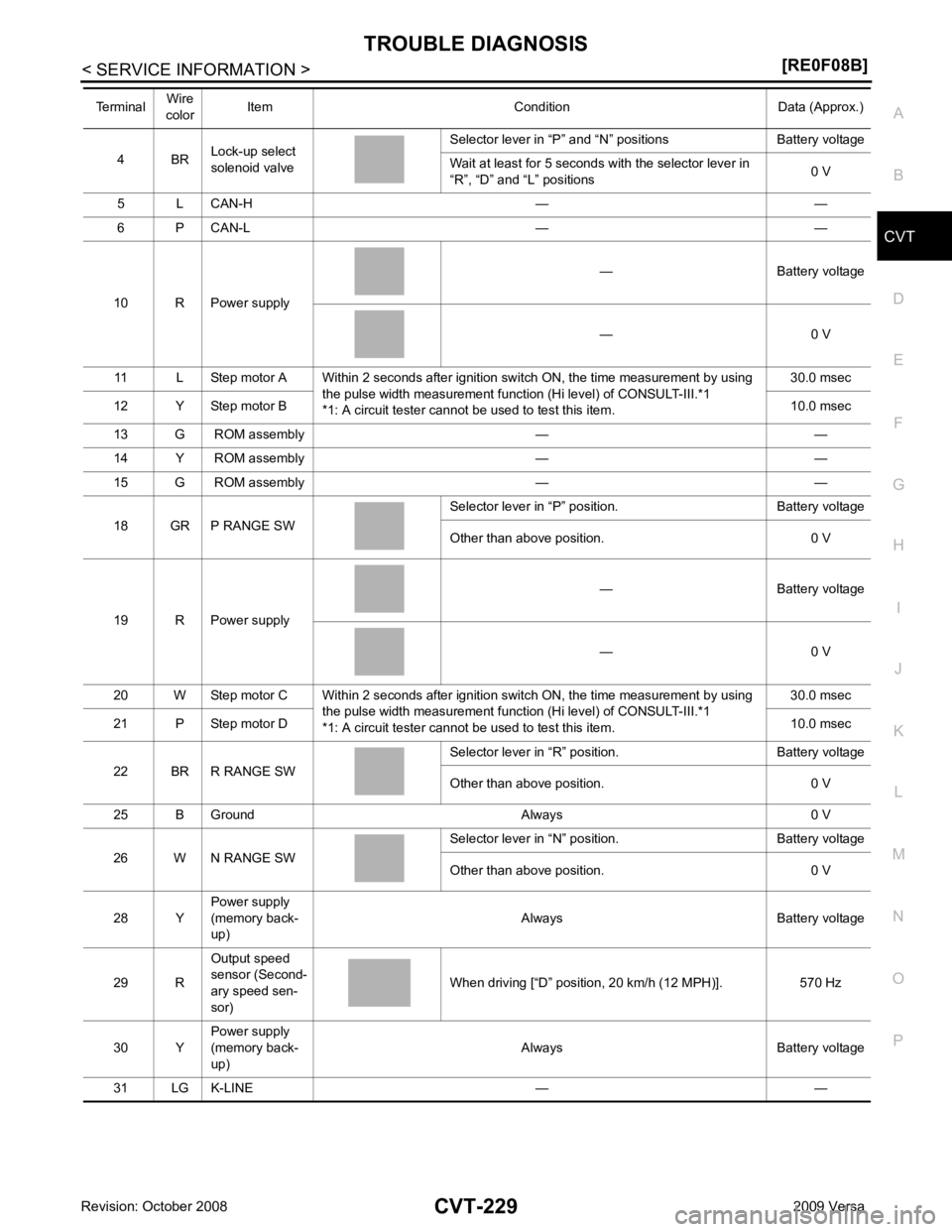
CVT
N
O P
4 BR
Lock-up select
solenoid valve Selector lever in “P” and “N
” positions Battery voltage
Wait at least for 5 seconds with the selector lever in
“R”, “D” and “L” positions 0 V
5 L CAN-H — —
6 P CAN-L — —
10 R Power supply — Battery voltage
— 0 V
11 L Step motor A Within 2 seconds after ignition switch ON, the time measurement by using the pulse width measurement function (Hi level) of CONSULT-III.*1
*1: A circuit tester cannot be used to test this item. 30.0 msec
12 Y Step motor B 10.0 msec
13 G ROM assembly — —
14 Y ROM assembly — —
15 G ROM assembly — —
18 GR P RANGE SW Selector lever in “P” po
sition. Battery voltage
Other than above position. 0 V
19 R Power supply — Battery voltage
— 0 V
20 W Step motor C Within 2 seconds after ignition switch ON, the time measurement by using the pulse width measurement function (Hi level) of CONSULT-III.*1
*1: A circuit tester cannot be used to test this item. 30.0 msec
21 P Step motor D 10.0 msec
22 BR R RANGE SW Selector lever in “R” po
sition. Battery voltage
Other than above position. 0 V
25 B Ground Always 0 V
26 W N RANGE SW Selector lever in “N” po
sition. Battery voltage
Other than above position. 0 V
28 Y Power supply
(memory back-
up) Always Battery voltage
29 R Output speed
sensor (Second-
ary speed sen-
sor) When driving [“D” position, 20 km/h (12 MPH)]. 570 Hz
30 Y Power supply
(memory back-
up) Always Battery voltage
31 LG K-LINE — —
Terminal
Wire
color Item Condition Data (Approx.)