2009 NISSAN LATIO fuel cap release
[x] Cancel search: fuel cap releasePage 1886 of 4331
![NISSAN LATIO 2009 Service Repair Manual EC-530< SERVICE INFOMATION >
[MR TYPE 1]
EVAPORATIVE EMISSION SYSTEM
Check EVAP canister as follows:
1. Block port B.
2. Blow air into port Aand check that it flows freely out of port C.
3. Release NISSAN LATIO 2009 Service Repair Manual EC-530< SERVICE INFOMATION >
[MR TYPE 1]
EVAPORATIVE EMISSION SYSTEM
Check EVAP canister as follows:
1. Block port B.
2. Blow air into port Aand check that it flows freely out of port C.
3. Release](/manual-img/5/57359/w960_57359-1885.png)
EC-530< SERVICE INFOMATION >
[MR TYPE 1]
EVAPORATIVE EMISSION SYSTEM
Check EVAP canister as follows:
1. Block port B.
2. Blow air into port Aand check that it flows freely out of port C.
3. Release blocked port B.
4. Apply vacuum pressure to port Band check that vacuum pres-
sure exists at the ports A and C.
5. Block port A and B.
6. Apply pressure to port Cand check that there is no leakage.
FUEL TANK VACUUM RELIEF VALVE (BUILT INTO FUEL FILLER CAP)
1. Wipe clean valve housing.
2. Check valve opening pressure and vacuum.
3. If out of specification, replace fuel filler cap as an assembly.
CAUTION:
Use only a genuine fuel filler cap as a replacement. If an incor-
rect fuel filler cap is used, the MIL may come on.
EVAP CANISTER PURGE VOLUME CONTROL SOLENOID VALVE
Refer to EC-815, " Component Inspection " .
FUEL TANK TEMPERATURE SENSOR
Refer to EC-759, " Component Inspection " .
EVAP CANISTER VENT CONTROL VALVE
Refer to EC-821, " Component Inspection " .
EVAP CONTROL SYSTEM PRESSURE SENSOR
Refer to EC-838, " Component Inspection " .
EVAP SERVICE PORT PBIB1212E
SEF445Y
Pressure: 15.3 - 20.0 kPa
(0.156 - 0.204 kg/cm 2
, 2.22 - 2.90 psi)
Vacuum: −6.0 to −3.4 kPa
( − 0.061 to −0.035 kg/cm 2
, −0.87 to −0.48 psi) SEF943S
Page 2143 of 4331
![NISSAN LATIO 2009 Service Repair Manual DTC P0420 THREE WAY CATALYST FUNCTION
EC-787
< SERVICE INFOMATION >
[MR TYPE 1] C
D E
F
G H
I
J
K L
M A EC
NP
O
DTC P0420 THREE WAY CATALYST FUNCTION
On Board Diagnosis Logic INFOID:0000000004537280
T NISSAN LATIO 2009 Service Repair Manual DTC P0420 THREE WAY CATALYST FUNCTION
EC-787
< SERVICE INFOMATION >
[MR TYPE 1] C
D E
F
G H
I
J
K L
M A EC
NP
O
DTC P0420 THREE WAY CATALYST FUNCTION
On Board Diagnosis Logic INFOID:0000000004537280
T](/manual-img/5/57359/w960_57359-2142.png)
DTC P0420 THREE WAY CATALYST FUNCTION
EC-787
< SERVICE INFOMATION >
[MR TYPE 1] C
D E
F
G H
I
J
K L
M A EC
NP
O
DTC P0420 THREE WAY CATALYST FUNCTION
On Board Diagnosis Logic INFOID:0000000004537280
The ECM monitors the switching frequency ratio of air fuel ratio (A/F)
sensor 1 and heated oxygen sensor 2.
A three way catalyst (manifold) with high oxygen storage capacity
will indicate a low switching frequency of heated oxygen sensor 2.
As oxygen storage capacity decr eases, the heated oxygen sensor 2
switching frequency will increase.
When the frequency ratio of air fuel ratio (A/F) sensor 1 and heated
oxygen sensor 2 approaches a specified limit value, the three way
catalyst (manifold) malfunction is diagnosed.
DTC Confirmation Procedure INFOID:0000000004537281
NOTE:
If DTC Confirmation Procedure has been previously conduc ted, always turn ignition switch OFF and wait at
least 10 seconds before conducting the next test.
WITH CONSULT-III
TESTING CONDITION:
Do not hold engine speed for more than the specified minutes below.
1. Turn ignition switch ON and select “DATA MONITOR” mode with CONSULT-III.
2. Start engine and warm it up to the normal operating temperature.
3. Turn ignition switch OFF and wait at least 10 seconds.
4. Start engine and keep the engine speed between 3,500 and 4,000 rpm for at least 1 minute under no load.
5. Let engine idle for 1 minute.
6. Make sure that “COOLAN TEMP/S” indicates more than 70 °C (158 °F).
If not, warm up engine and go to next step when “COOLAN TEMP/S” indication reaches to 70°C (158 °F).
7. Open engine hood.
8. Select “DTC & SRT CONFIRMATION” then “SRT WORK SUPPORT” mode with CONSULT-III.
9. Rev engine up to 2,000 to 3,000 rpm and hold it for 3 consecutive minutes then release the accelerator pedal completely.
If “INCMP” of “CATALYST” changed to “CMPLT”, go to step 12.
10. Wait 5 seconds at idle.
11. Rev engine up to 2,000 to 3,000 rpm and maintain it unt il “INCMP” of “CATALYST” changes to “CMPLT” (It
will take approximately 5 minutes).
If not “CMPLT”, stop engine and cool it down to less than 70 °C (158 °F) and then retest from step 1.
12. Check 1st trip DTC. If 1st trip DTC is detected, go to EC-788, " Diagnosis Procedure " .
Overall Function Check INFOID:0000000004537282
Use this procedure to check the overall function of the th ree way catalyst (manifold). During this check, a 1st
trip DTC might not be confirmed. SEF484YB
DTC No. Trouble diagnosis name DTC detecting condition Possible cause
P0420
0420 Catalyst system efficiency
below threshold • Three way catalyst (manifold) does not operate
properly.
• Three way catalyst (manifold) does not have enough oxygen storage capacity. • Three way catalyst (manifold)
• Exhaust tube
• Intake air leaks
• Fuel injector
• Fuel injector leaks
• Spark plug
• Improper ignition timing
Page 2395 of 4331
![NISSAN LATIO 2009 Service Repair Manual EVAPORATIVE EMISSION SYSTEM
EC-1039
< SERVICE INFOMATION >
[MR TYPE 2] C
D E
F
G H
I
J
K L
M A EC
NP
O
Check EVAP canister as follows:
1. Block port B.
2. Blow air into port Aand check that it flows NISSAN LATIO 2009 Service Repair Manual EVAPORATIVE EMISSION SYSTEM
EC-1039
< SERVICE INFOMATION >
[MR TYPE 2] C
D E
F
G H
I
J
K L
M A EC
NP
O
Check EVAP canister as follows:
1. Block port B.
2. Blow air into port Aand check that it flows](/manual-img/5/57359/w960_57359-2394.png)
EVAPORATIVE EMISSION SYSTEM
EC-1039
< SERVICE INFOMATION >
[MR TYPE 2] C
D E
F
G H
I
J
K L
M A EC
NP
O
Check EVAP canister as follows:
1. Block port B.
2. Blow air into port Aand check that it flows freely out of port C.
3. Release blocked port B.
4. Apply vacuum pressure to port Band check that vacuum pres-
sure exists at the ports A and C.
5. Block port A and B.
6. Apply pressure to port Cand check that there is no leakage.
FUEL TANK VACUUM RELIEF VALVE (BUILT INTO FUEL FILLER CAP) 1. Wipe clean valve housing.
2. Check valve opening pressure and vacuum.
3. If out of specificat ion, replace fuel filler cap as an assembly.
CAUTION:
Use only a genuine fuel filler cap as a replacement. If an incor-
rect fuel filler cap is used, the MIL may come on.
EVAP CANISTER PURGE VOLUME CONTROL SOLENOID VALVE
Refer to EC-1329, " Component Inspection " .
FUEL TANK TEMPERATURE SENSOR Refer to EC-1273, " Component Inspection " .
EVAP CANISTER VENT CONTROL VALVE Refer to EC-1340, " Component Inspection " .
EVAP CONTROL SYSTEM PRESSURE SENSOR Refer to EC-1350, " Component Inspection " .
EVAP SERVICE PORT PBIB1212E
SEF445Y
Pressure: 15.3 - 20.0 kPa
(0.156 - 0.204 kg/cm 2
, 2.22 - 2.90 psi)
Vacuum: −6.0 to −3.4 kPa
( − 0.061 to −0.035 kg/cm 2
, −0.87 to −0.48 psi) SEF943S
Page 2661 of 4331
![NISSAN LATIO 2009 Service Repair Manual DTC P0420 THREE WAY CATALYST FUNCTION
EC-1305
< SERVICE INFOMATION >
[MR TYPE 2] C
D E
F
G H
I
J
K L
M A EC
NP
O
DTC P0420 THREE WAY CATALYST FUNCTION
On Board Diagnosis Logic INFOID:0000000004500166
NISSAN LATIO 2009 Service Repair Manual DTC P0420 THREE WAY CATALYST FUNCTION
EC-1305
< SERVICE INFOMATION >
[MR TYPE 2] C
D E
F
G H
I
J
K L
M A EC
NP
O
DTC P0420 THREE WAY CATALYST FUNCTION
On Board Diagnosis Logic INFOID:0000000004500166](/manual-img/5/57359/w960_57359-2660.png)
DTC P0420 THREE WAY CATALYST FUNCTION
EC-1305
< SERVICE INFOMATION >
[MR TYPE 2] C
D E
F
G H
I
J
K L
M A EC
NP
O
DTC P0420 THREE WAY CATALYST FUNCTION
On Board Diagnosis Logic INFOID:0000000004500166
The ECM monitors the switching frequency ratio of air fuel ratio (A/F)
sensor 1 and heated oxygen sensor 2.
A three way catalyst (manifold) with high oxygen storage capacity
will indicate a low switching frequency of heated oxygen sensor 2.
As oxygen storage capacity decr eases, the heated oxygen sensor 2
switching frequency will increase.
When the frequency ratio of air fuel ratio (A/F) sensor 1 and heated
oxygen sensor 2 approaches a specified limit value, the three way
catalyst (manifold) malfunction is diagnosed.
DTC Confirmation Procedure INFOID:0000000004500167
NOTE:
If DTC Confirmation Procedure has been previously conduc ted, always turn ignition switch OFF and wait at
least 10 seconds before conducting the next test.
WITH CONSULT-III
TESTING CONDITION:
Do not hold engine speed for more than the specified minutes below.
1. Turn ignition switch ON and select “DATA MONITOR” mode with CONSULT-III.
2. Start engine and warm it up to the normal operating temperature.
3. Turn ignition switch OFF and wait at least 10 seconds.
4. Start engine and keep the engine speed between 3,500 and 4,000 rpm for at least 1 minute under no load.
5. Let engine idle for 1 minute.
6. Make sure that “COOLAN TEMP/S” indicates more than 70 °C (158 °F).
If not, warm up engine and go to next step when “COOLAN TEMP/S” indication reaches to 70°C (158 °F).
7. Open engine hood.
8. Select “DTC & SRT CONFIRMATION” then “SRT WORK SUPPORT” mode with CONSULT-III.
9. Rev engine up to 2,000 to 3,000 rpm and hold it for 3 consecutive minutes then release the accelerator pedal completely.
If “INCMP” of “CATALYST” changed to “CMPLT”, go to step 12.
10. Wait 5 seconds at idle.
11. Rev engine up to 2,000 to 3,000 rpm and maintain it unt il “INCMP” of “CATALYST” changes to “CMPLT” (It
will take approximately 5 minutes).
If not “CMPLT”, stop engine and cool it down to less than 70 °C (158 °F) and then retest from step 1.
12. Check 1st trip DTC. If 1st trip DTC is detected, go to EC-1306, " Diagnosis Procedure " .
Overall Function Check INFOID:0000000004500168
Use this procedure to check the overall function of the th ree way catalyst (manifold). During this check, a 1st
trip DTC might not be confirmed. SEF484YB
DTC No. Trouble diagnosis name DTC detecting condition Possible cause
P0420
0420 Catalyst system efficiency
below threshold • Three way catalyst (manifold) does not operate
properly.
• Three way catalyst (manifold) does not have enough oxygen storage capacity. • Three way catalyst (manifold)
• Exhaust tube
• Intake air leaks
• Fuel injector
• Fuel injector leaks
• Spark plug
• Improper ignition timing
Page 2956 of 4331

EM
NP
O
Commercial Service Tools INFOID:0000000004784268
EM03470000
(J-8037)
Piston ring compressor Installing piston assembly into cylinder bore
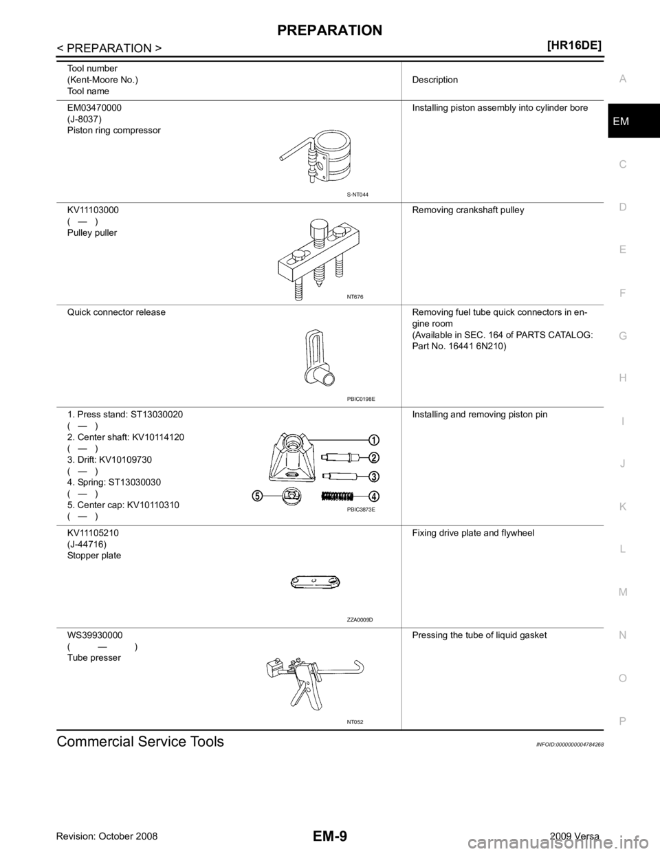
KV11103000
( — )
Pulley puller Removing crankshaft pulley
Quick connector release Removing fuel tube quick connectors in en- gine room
(Available in SEC. 164 of PARTS CATALOG:
Part No. 16441 6N210)
1. Press stand: ST13030020
( — )
2. Center shaft: KV10114120
( — )
3. Drift: KV10109730
( — )
4. Spring: ST13030030
( — )
5. Center cap: KV10110310
( — ) Installing and removing piston pin
KV11105210
(J-44716)
Stopper plate Fixing drive plate and flywheel
WS39930000
( — )
Tube presser Pressing the tube of liquid gasket
Tool number
(Kent-Moore No.)
Tool name Description PBIC0198E
PBIC3873E
ZZA0009D
NT052
Page 2982 of 4331

EM
NP
O
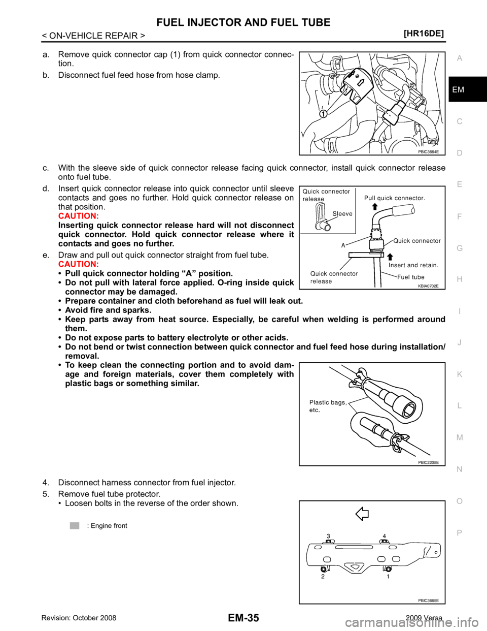
a. Remove quick connector cap (1) from quick connector connec-
tion.
b. Disconnect fuel feed hose from hose clamp.
c. With the sleeve side of quick connector release facing quick connector, install quick connector release onto fuel tube.
d. Insert quick connector release into quick connector until sleeve contacts and goes no further. Hold quick connector release on
that position.
CAUTION:
Inserting quick connector re lease hard will not disconnect
quick connector. Hold qui ck connector release where it
contacts and goes no further.
e. Draw and pull out quick connector straight from fuel tube. CAUTION:
• Pull quick connector holding “A” position.
• Do not pull with lateral force applied. O-ring inside quick
connector may be damaged.
• Prepare container and cloth be forehand as fuel will leak out.
• Avoid fire and sparks.
• Keep parts away from heat source. Especially, be careful when welding is performed around
them.
• Do not expose parts to battery electrolyte or other acids.
• Do not bend or twist connection between quick co nnector and fuel feed hose during installation/
removal.
• To keep clean the connecting portion and to avoid dam-
age and foreign materials, cover them completely with
plastic bags or something similar.
4. Disconnect harness connector from fuel injector.
5. Remove fuel tube protector. • Loosen bolts in the reverse of the order shown. KBIA0702E
Page 3104 of 4331

EM
NP
O
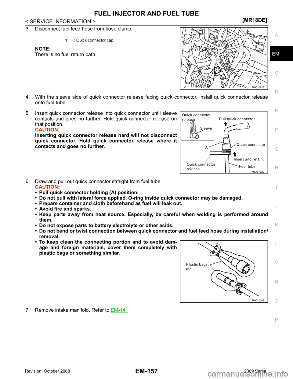
3. Disconnect fuel feed hose from hose clamp.
NOTE:
There is no fuel return path.
4. With the sleeve side of quick connector release facing quick connector, install quick connector release onto fuel tube.
5. Insert quick connector release into quick connector until sleeve contacts and goes no further. Hold quick connector release on
that position.
CAUTION:
Inserting quick connector re lease hard will not disconnect
quick connector. Hold qui ck connector release where it
contacts and goes no further.
6. Draw and pull out quick connector straight from fuel tube. CAUTION:
• Pull quick connector holding (A) position.
• Do not pull with lateral force applied. O-ring inside quick connector may be damaged.
• Prepare container and cloth be forehand as fuel will leak out.
• Avoid fire and sparks.
• Keep parts away from heat source. Especially, be careful when welding is performed around
them.
• Do not expose parts to battery electrolyte or other acids.
• Do not bend or twist connection between quick co nnector and fuel feed hose during installation/
removal.
• To keep clean the connecting portion and to avoid dam-
age and foreign materials, cover them completely with
plastic bags or something similar.
7. Remove intake manifold. Refer to EM-141 .
1 : Quick connector cap
KBIA0702E
PBIC2205E
Page 3224 of 4331

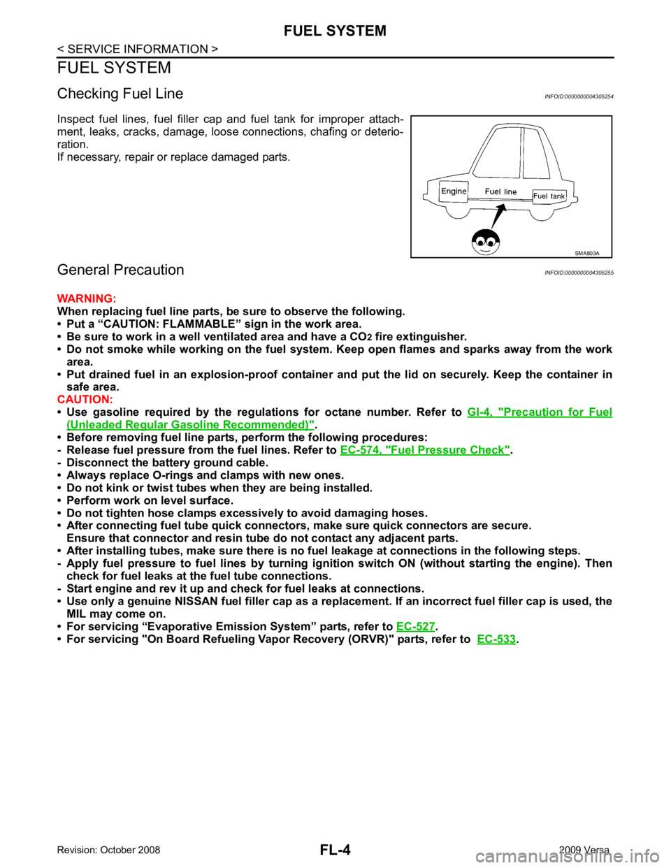
Precaution for Fuel
(Unleaded Regular Gasoline Recommended) " .
• Before removing fuel line parts, perform the following procedures:
- Release fuel pressure from the fuel lines. Refer to EC-574, " Fuel Pressure Check " .
- Disconnect the battery ground cable.
• Always replace O-rings and clamps with new ones.
• Do not kink or twist tubes when they are being installed.
• Perform work on level surface.
• Do not tighten hose clamps excessi vely to avoid damaging hoses.
• After connecting fuel tube quick connect ors, make sure quick connectors are secure.
Ensure that connector and resin tube do not contact any adjacent parts.
• After installing tubes, make sure there is no fuel leakage at connections in the following steps.
- Apply fuel pressure to fuel lines by turning ignition switch ON (without starting the engine). Then
check for fuel leaks at the fuel tube connections.
- Start engine and rev it up and check for fuel leaks at connections.
• Use only a genuine NISSAN fuel filler cap as a replacemen t. If an incorrect fuel filler cap is used, the
MIL may come on.
• For servicing “Evaporative Emi ssion System” parts, refer to EC-527 .
• For servicing "On Board Refueling Vapo r Recovery (ORVR)" parts, refer to EC-533 .