Page 3108 of 4331

EM
NP
O
Removal and Installation
INFOID:0000000004307143
CAUTION:
The rotating direction indicated in the text indicates all directions seen from the engine front.
REMOVAL 1. Remove front RH wheel. Refer to WT-7, " Rotation " .
2. Remove front fender protector (RH). Refer to EI-24, " Removal and Installation " .
3. Drain engine oil. Refer to LU-17, " Changing Engine Oil " .
CAUTION:
Perform this step when engine is cold.
4. Remove the following parts. • Rocker cover: Refer to EM-153, " Component " .
• Drive belt: Refer to EM-136, " Removal and Installation " .
• Water pump pulley: Refer to CO-43, " Component " .
• Ground cable (between engine bracket (RH) and radiator core support)
5. Support the bottom surface of engine using a transmission jack, and then remove the engine bracket and insulator (RH). Refer to EM-195, " Component " .
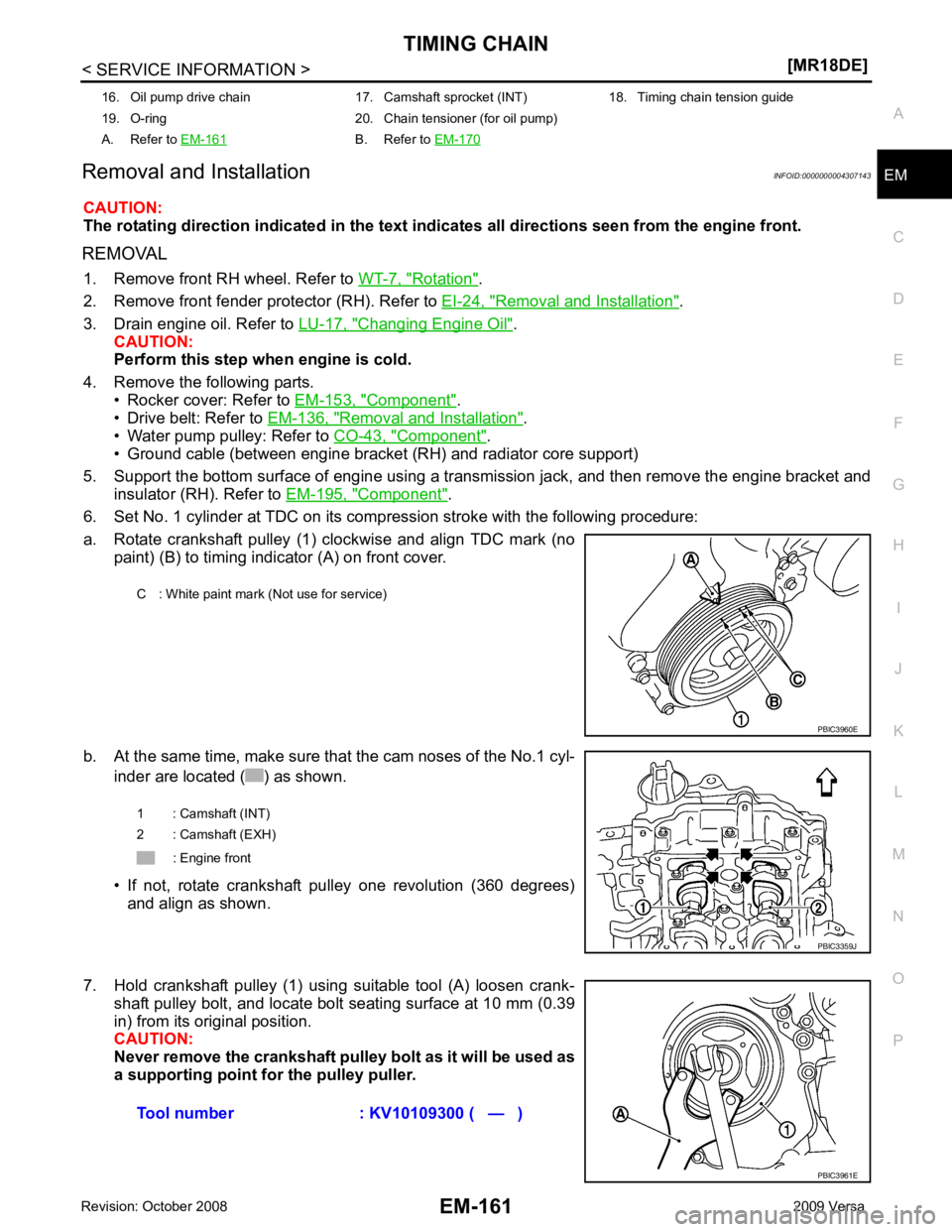
6. Set No. 1 cylinder at TDC on its compression stroke with the following procedure:
a. Rotate crankshaft pulley (1) clockwise and align TDC mark (no paint) (B) to timing indicator (A) on front cover.
b. At the same time, make sure that the cam noses of the No.1 cyl- inder are located ( ) as shown.
• If not, rotate crankshaft pulley one revolution (360 degrees) and align as shown.
7. Hold crankshaft pulley (1) using suitable tool (A) loosen crank- shaft pulley bolt, and locate bolt seating surface at 10 mm (0.39
in) from its original position.
CAUTION:
Never remove the crankshaft pulley bolt as it will be used as
a supporting point for the pulley puller.
16. Oil pump drive chain 17. Camshaft sprocket (INT) 18. Timing chain tension guide
19. O-ring 20. Chain tensioner (for oil pump)
A. Refer to EM-161 B. Refer to
EM-170 C : White paint mark (Not use for service)
Page 3109 of 4331
Component " .
NOTE:
When crankshaft sprocket, oil pump sprocket and other related parts are not removed, this step is unnec-
essary.
10. Remove intake valve timing control solenoid valve.
11. Remove drive belt auto-tensioner.
12. Loosen bolts in reverse order as shown.
13. Cut liquid gasket by prying the position ( ) shown, and then remove the front cover.
CAUTION:
• Be careful not to damage the mating surface.
• A more adhesive liquid gasket is applied compared to pre- vious types when shipped, so it should not be forced off
the position not specified.
14. Remove front oil seal from front cover. • Lift up front oil seal using a suitable tool.
CAUTION:
Be careful not to damage front cover. Tool number : KV11103000 ( — )
PBIC3164J
PBIC3357J
Page 3125 of 4331

Component " .
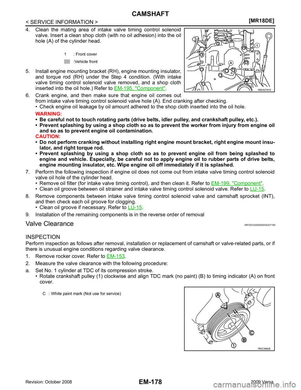
6. Crank engine, and then make sure that engine oil comes out from intake valve timing control solenoid valve hole (A). End cranking after checking.
• Check engine oil leakage by oil amount adhered to the shop cloth inserted into the oil hole.
WARNING:
• Be careful not to touch rotating parts (drive be lts, idler pulley, and crankshaft pulley, etc.).
• Prevent splashing by using a shop cloth so as to prevent the worker from injury from engine oil
and so as to prevent engi ne oil contamination.
CAUTION:
• Do not perform cranking without installing right engine mount bracket, right engine mount insu-
lator, and right torque rod.
• Prevent splashing by using a shop cloth so as to prevent engine oil from being splashed to
engine and vehicle. Especially, be careful not to apply engine oil to rubber parts of drive belts,
engine mounting insulator, etc. Wipe engi ne oil off immediately if it is splashed.
7. Perform the following inspection if engine oil does not come out from intake valve timing control solenoid valve oil hole of the cylinder head.
• Remove oil filter (for intake valve timing control), and then clean it. Refer to EM-199, " Component " .
• Clean oil groove between oil strainer and intake valve timing control solenoid valve. Refer to LU-15 .
8. Remove components between intake valve timing c ontrol solenoid valve and camshaft sprocket (INT),
and then check each oil groove for clogging.
• Clean oil groove if necessary. Refer to LU-15 .
9. Installation of the remaining components is in the reverse order of removal
Valve Clearance INFOID:0000000004307146
INSPECTION
Perform inspection as follows after removal, installation or replacement of camshaft or valve-related parts, or if
there is unusual engine conditions regarding valve clearance.
1. Remove rocker cover. Refer to EM-153 .
2. Measure the valve clearance with the following procedure:
a. Set No. 1 cylinder at TDC of its compression stroke. • Rotate crankshaft pulley (1) clockwise and align TDC mark (no paint) (B) to timing indicator (A) on front
cover. 1 : Front cover
:Vehicle front
Page 3134 of 4331
![NISSAN LATIO 2009 Service Repair Manual CYLINDER HEAD
EM-187
< SERVICE INFORMATION >
[MR18DE] C
D E
F
G H
I
J
K L
M A EM
NP
O
4. Remove drive belt. Refer to
EM-136, " Removal and Installation " .
5. Remove the following components and rela NISSAN LATIO 2009 Service Repair Manual CYLINDER HEAD
EM-187
< SERVICE INFORMATION >
[MR18DE] C
D E
F
G H
I
J
K L
M A EM
NP
O
4. Remove drive belt. Refer to
EM-136, " Removal and Installation " .
5. Remove the following components and rela](/manual-img/5/57359/w960_57359-3133.png)
CYLINDER HEAD
EM-187
< SERVICE INFORMATION >
[MR18DE] C
D E
F
G H
I
J
K L
M A EM
NP
O
4. Remove drive belt. Refer to
EM-136, " Removal and Installation " .
5. Remove the following components and related parts. • Exhaust manifold; Refer to EM-144 .
• Intake manifold; Refer to EM-141 .
• Fuel tube and fuel injector assembly; Refer to EM-156 .
• Water outlet; Refer to CO-47 .
• Rocker cover; Refer to EM-153 .
• Front cover, timing chain; Refer to EM-160 .
• Camshaft; Refer to EM-170 .
6. Remove cylinder head. • Loosen bolts in reverse order as shown.
• Using TORX socket (size E18), loosen cylinder head bolts.
7. Remove cylinder head gasket.
INSPECTION AFTER REMOVAL
Cylinder Head Bolts Outer Diameter • Cylinder head bolts are tightened by plastic zone tightening method. Whenever the size difference between (d1) and (d2)
exceeds the limit, replac e them with a new one.
• If reduction of outer diameter appear s in a position other than (d2),
use it as (d2) point.
Cylinder Head Distortion NOTE:
When performing this inspection, cylinder block distortion should be also checked. Refer to EM-216, " Inspec-
tion After Disassembly " .
1. Wipe off engine oil and remove water scale (like deposit ), gasket, sealant, carbon, etc. with a scraper.
CAUTION:
Never allow gasket debris to enter passag es for engine oil or engine coolant.
2. At each of several locations on bottom surface of cylinder head, measure the distortion in six di rections using straightedge (A)
and feeler gauge (B).
• If it exceeds the limit, replace cylinder head.
INSTALLATION 1. Install cylinder head gasket.
2. Apply new engine oil to threads and seating surface of bolts. CAUTION: : Engine front
PBIC3206J
Limit [(d1) – (d2)]: 0.15 mm (0.0059 in)
PBIC3994E
Limit: 0.1 mm (0.004 in)
PBIC3207J