2009 NISSAN LATIO relay
[x] Cancel search: relayPage 462 of 4331

BL
N
O P
CONTENTS
BODY, LOCK & SECURITY SYSTEM
SERVICE INFORMATION .. ..........................4
PRECAUTIONS .............................................. .....4
Precaution for Supplemental Restraint System
(SRS) "AIR BAG" and "SEAT BELT PRE-TEN-
SIONER" ............................................................. ......
4
Precaution Necessary fo r Steering Wheel Rota-
tion After Battery Disconnect ............................... ......
4
Precaution for Procedure without Cowl Top Cover ......5
Precaution for Work ............................................ ......5
PREPARATION .............................................. .....6
Special Service Tool ........................................... ......6
Commercial Service Tool .................................... ......6
SQUEAK AND RATTLE TROUBLE DIAG-
NOSES ........................ ........................................7
Work Flow ........................................................... ......7
Generic Squeak and Rattle Troubleshooting ...... ......9
Diagnostic Worksheet ......................................... ....11
HOOD ............................................................. ....13
Fitting Adjustment ............................................... ....13
Removal and Installation .........................................14
Removal and Installation of Hood Lock Control .. ....15
Hood Lock Control Inspec tion .................................17
RADIATOR CORE SUPPORT ....................... ....19
Removal and Installation .........................................19
FRONT FENDER ............................................ ....21
Removal and Installation .........................................21
POWER DOOR LOCK SYSTEM .................... ....22
Component Parts and Harness Connector Loca-
tion ...................................................................... ....
22
System Description ............................................. ....23
CAN Communication System Description ........... ....25
Schematic ........................................................... ....26
Wiring Diagram - D/LOCK - ................................. ....27
Schematic ........................................................... ....31
Wiring Diagram - D/LOCK - ................................. ....32 Terminal and Reference
Value for BCM ..................37
Work Flow ............................................................ ....41
CONSULT-III Function (B CM) .................................41
Trouble Diagnosis Symptom Chart ...................... ....43
BCM Power Supply and Ground Circuit Inspection ....43
Door Switch Check (Hatchback) .......................... ....44
Door Switch Check (Sedan) ................................ ....47
Key Switch (Insert) Check ................................... ....48
Door Lock and Unlock Switch Check .................. ....49
Front Door Lock Assembly LH (Actuator) Check .....52
Door Lock Actuator Check (Front RH and Rear
LH/RH) ................................................................. ....
53
Front Door Key Cylinder S witch LH Check ..............54
Passenger Select Unlock Relay Circuit Inspection
(With Intelligent Key) ........................................... ....
55
REMOTE KEYLESS ENTRY SYSTEM ............. 58
Component Parts and Harness Connector Loca-
tion ....................................................................... ....
58
System Description .............................................. ....58
CAN Communication System Description ........... ....60
Schematic ............................................................ ....61
Wiring Diagram - KEYLES - ................................ ....62
Terminal and Reference Value for BCM ..................65
How to Perform Trouble Diagnosis ...................... ....69
Preliminary Check ............................................... ....69
CONSULT-III Function (B CM) .................................69
Work Flow ............................................................ ....71
Trouble Diagnosis Symptom Chart ...................... ....71
Keyfob Battery and Function Check .................... ....72
ACC Switch Check .............................................. ....74
Door Switch Check (Hatchback) .......................... ....74
Door Switch Check (Sedan) ................................ ....76
Key Switch (Insert) Check ................................... ....78
Hazard Function Check ....................................... ....78
Horn Function Check ........................................... ....79
Interior Lamp and Ignition Keyhole Illumination
Function Check .................................................... ....
79
Remote Keyless Entry Rece iver Check ...................80
Keyfob Function (Lock) Check ............................ ....82
Page 484 of 4331

BL
N
O P
System Description
INFOID:0000000004304987
Power is supplied at all times
• through 40A fusible link (letter g , located in the fuse and fusible link box)
• to BCM terminal 70
• through 10A fuse [No. 8, located in the fuse block (J/B)]
• to BCM terminal 57
• through 10A fuse [No. 14, located in the fuse block (J/B)]
• to key switch terminal 2 (without Intelligent Key system)
• through 10A fuse [No. 31, located in the fuse block (J/B)]
• to key switch and ignition knob switch terminals 2 and 4 (with Intelligent Key system).
When key switch is ON (key is inserted in ignition key cylinder), power is supplied
• through key switch terminal 1 (without Intelligent Key system) or key switch and ignition knob terminal 1 (with Intelligent Key system)
• to BCM terminal 37.
Ground is supplied
• to BCM terminal 67
• through body grounds M57 and M61.
LOCK OPERATION When the door is locked with main power window and door lock/unlock switch, ground is supplied
• to BCM terminal 45
• through main power window and door lock and unlock switch terminals 17 and 18
• through body grounds M57 and M61.
When the door is locked with power window and door lock/unlock switch RH, ground is supplied
• to BCM terminal 45
• through power window and door lock and unlock switch RH terminals 1 and 3
• through body grounds M57 and M61.
When the door is locked with front door ke y cylinder switch LH, ground is supplied
• to BCM terminal 8
• through front door key cylinder switch LH terminals 1 and 2
• through body grounds M57 and M61.
UNLOCK OPERATION When the door is unlocked with main power window and door lock/unlock switch, ground is supplied
• to BCM terminal 46
• through main power window and door lock/unlock switch terminals 6 and 17
• through body grounds M57 and M61.
When the door is unlocked with power window and door lock/unlock switch RH, ground is supplied
• to BCM terminal 46
• through power window and door lock and unlock switch RH terminals 2 and 3
• through body grounds M57 and M61.
When the door is unlocked with front door ke y cylinder switch LH, ground is supplied
• to BCM terminal 7
• through front door key cylinder switch LH terminals 2 and 3
• through body grounds M57 and M61.
When the front door switch LH is ON (door is OPEN), ground is supplied
• to BCM terminal 47
• through front door switch LH terminal 2
• through front door switch LH case ground.
When the front door switch RH is ON (door is OPEN), ground is supplied
• to BCM terminal 12
• through front door switch RH terminal 2
• through front door switch RH case ground. 10. Key switch and key lock solenoid M27
(without Intelligent key) 11. Main power window and door lock/un-
lock switch D7, D8
Power window and door lock/unlock
switch RH D105 12. Fuse block (with Intelligent Key)
(view with instrument panel LH re-
moved)
13. Passenger select unlock relay M2 (with Intelligent Key) 14. Back door lock assembly (back door
switch) D405 (hatchback view with back
door open) 15. Combination meter M24
Page 504 of 4331
BL
N
O P
*: With Remote Keyless Entry system
**: With Intelligent Key system
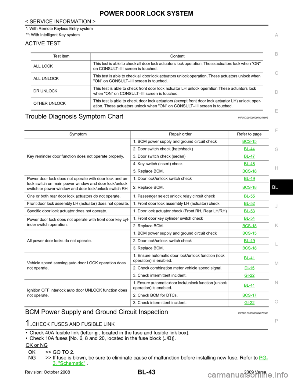
ACTIVE TEST
Trouble Diagnosis Symptom Chart INFOID:0000000004304996
BCM Power Supply and Gr ound Circuit Inspection INFOID:0000000004678560OK >> GO TO 2.
NG >> If fuse is blown, be sure to eliminate caus e of malfunction before installing new fuse. Refer to PG-3, " Schematic " .
Test item Content
ALL LOCK This test is able to check all door lock actuators lock operation. These actuators lock when "ON"
on CONSULT–III screen is touched.
ALL UNLOCK This test is able to check all door lock actuators unlock operation. These actuators unlock when
"ON" on CONSULT–III screen is touched.
DR UNLOCK This test is able to check front door lock actuator LH unlock operation.These actuators lock
when "ON" on CONSULT– III screen is touched.
OTHER UNLOCK This test is able to check door lock actuators (except front door lock actuator LH) unlock oper-
ation. These actuators unlock when "ON" on CONSULT–III screen is touched. Symptom Repair order Refer to page
Key reminder door function does not operate properly. 1. BCM power supply and ground circuit check
BCS-15 2. Door switch check (hatchback)
BL-44 3. Door switch check (sedan)
BL-47 4. Key switch (insert) check
BL-48 5. Replace BCM.
BCS-18Power door lock does not operate with door lock and un-
lock switch on main power window and door lock/unlock
switch or power window and door lock/unlock switch RH 1. Door lock/unlock switch check
BL-49 2. Replace BCM.
BCS-18One or both rear door lock actuators do not operate. 1. Passenger select unlock relay circuit check
BL-55Front door lock assembly LH (actuator) does not operate. 1. Front door lock assembly LH (actuator) check
BL-52Specific door lock actuator does not operate. 1. Door lock actuator check (Front RH, Rear LH/RH)
BL-53Power door lock does not operate with front door key cyl-
inder switch operation. 1. Front door key cylinder switch check
BL-54 2. Replace BCM.
BCS-18All power door locks do not operate.
1. BCM power supply and ground circuit check
BCS-15 2. Door lock/unlock switch check
BL-49 3. Replace BCM.
BCS-18Vehicle speed sensing auto door LOCK operation does
not operate. 1. Ensure automatic door lock/unlock function (lock
operation) is enabled. BL-41 2. Check combination meter vehicle speed signal.
DI-15 3. Check intermittent incident.
GI-22Ignition OFF interlock auto door UNLOCK function does
not operate. 1. Ensure automatic door lock/unlock function (unlock
operation) is enabled. BL-41 2. Check BCM for DTCs.
BCS-17 3. Check intermittent incident.
GI-22
Page 516 of 4331
BL
N
O P
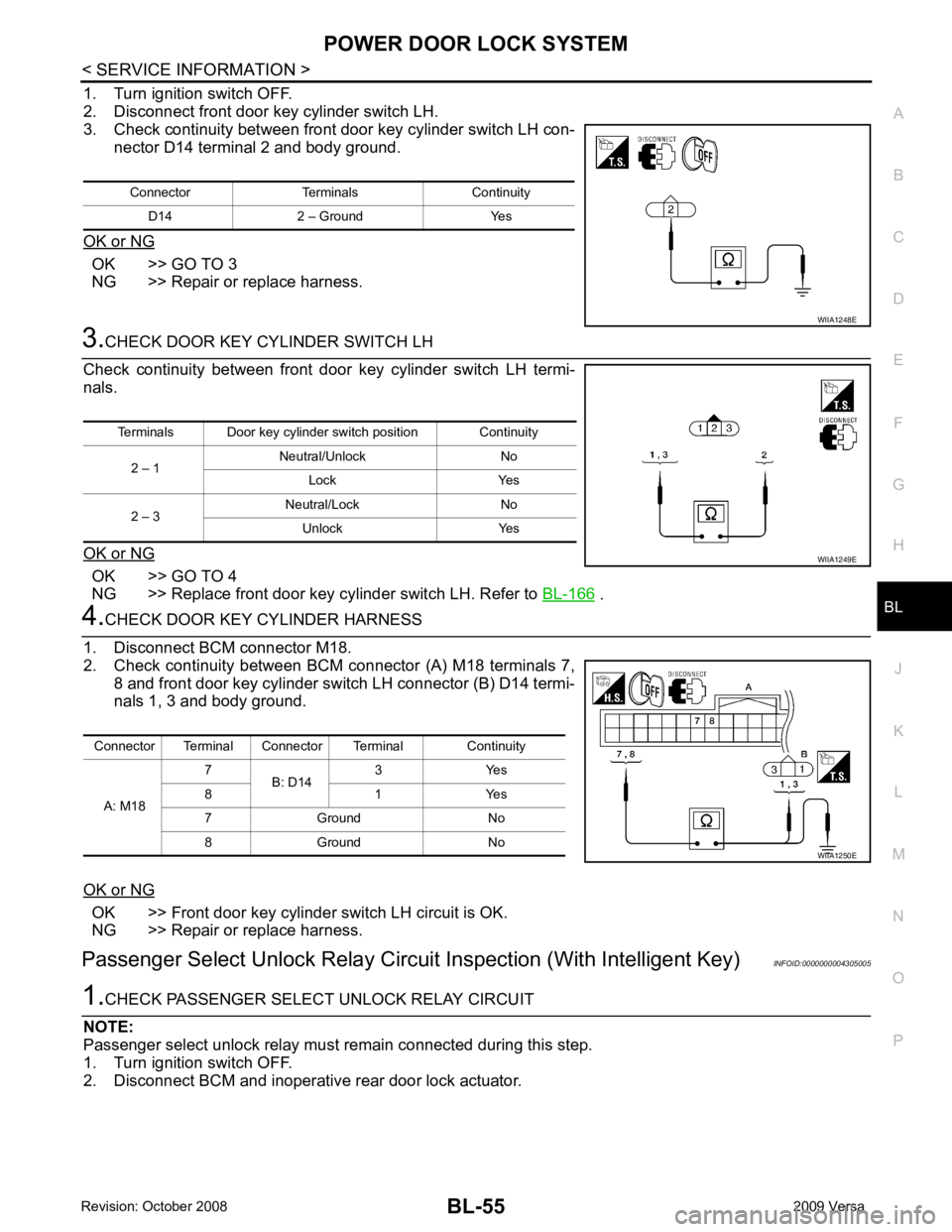
1. Turn ignition switch OFF.
2. Disconnect front door key cylinder switch LH.
3. Check continuity between front door key cylinder switch LH con-
nector D14 terminal 2 and body ground.
OK or NG OK >> GO TO 3
NG >> Repair or replace harness. OK >> GO TO 4
NG >> Replace front door key cylinder switch LH. Refer to BL-166 .
OK >> Front door key cylinder switch LH circuit is OK.
NG >> Repair or replace harness.
Passenger Select Unlock Relay Circ uit Inspection (With Intelligent Key) INFOID:0000000004305005
Page 517 of 4331
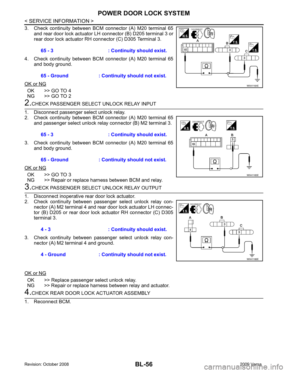
OK >> GO TO 4
NG >> GO TO 2 OK >> GO TO 3
NG >> Repair or replace harness between BCM and relay. OK >> Replace passenger select unlock relay.
NG >> Repair or replace harness between relay and actuator.
Page 618 of 4331
INTELLIGENT KEY SYSTEM
BL-157
< SERVICE INFORMATION >
C
D E
F
G H
J
K L
M A
B BL
N
O P
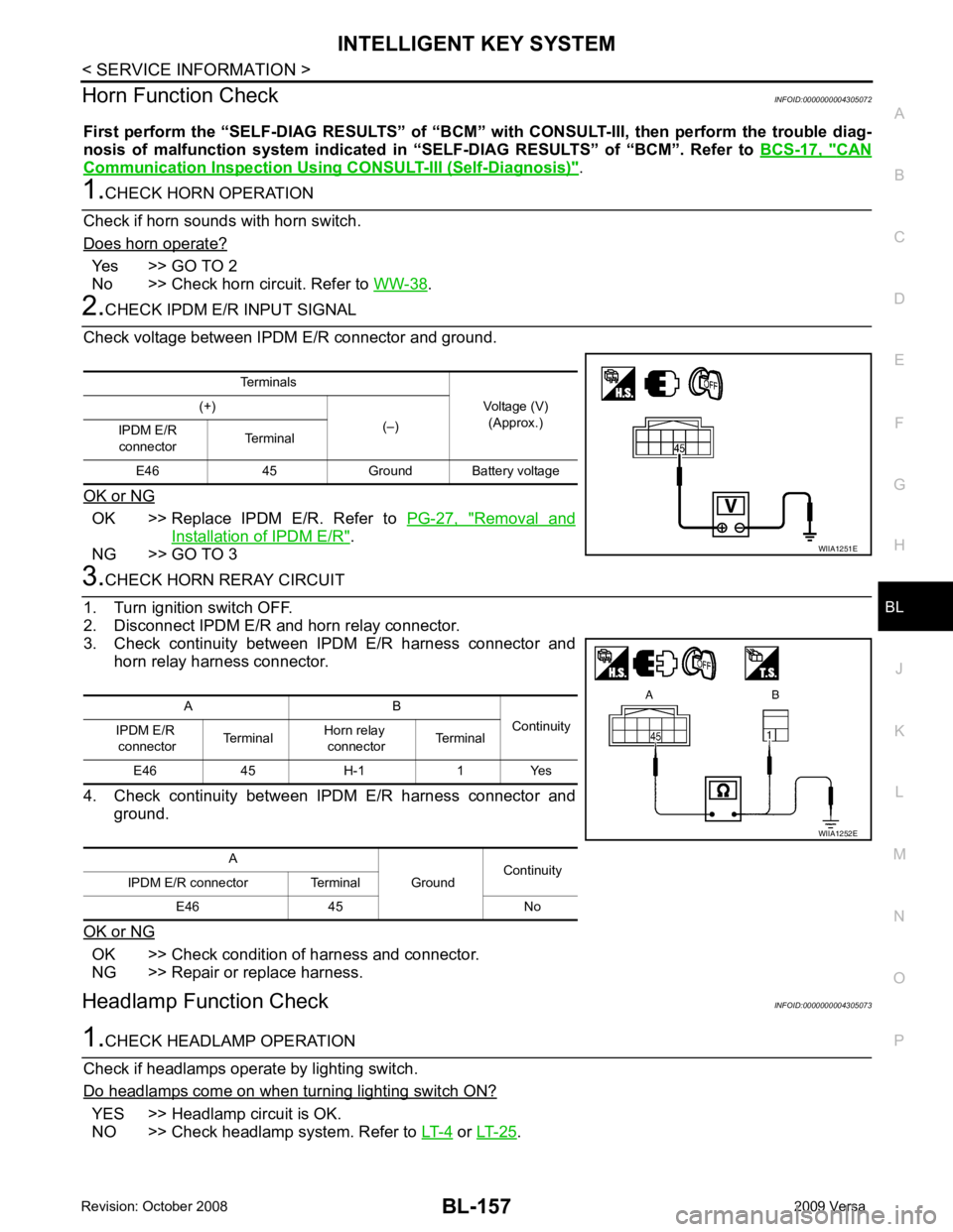
Horn Function Check
INFOID:0000000004305072
First perform the “SELF-DIAG RESULTS” of “BCM” with CONSULT-III, then perform the trouble diag-
nosis of malfunction system indicated in “ SELF-DIAG RESULTS” of “BCM”. Refer to BCS-17, " CAN
Communication Inspection Using CONSULT-III (Self-Diagnosis) " .
1.
CHECK HORN OPERATION
Check if horn sounds with horn switch.
Does horn operate? Yes >> GO TO 2
No >> Check horn circuit. Refer to WW-38 .
2.
CHECK IPDM E/R INPUT SIGNAL
Check voltage between IPDM E/R connector and ground.
OK or NG OK >> Replace IPDM E/R. Refer to
PG-27, " Removal and
Installation of IPDM E/R " .
NG >> GO TO 3 3.
CHECK HORN RERAY CIRCUIT
1. Turn ignition switch OFF.
2. Disconnect IPDM E/R and horn relay connector.
3. Check continuity between IPDM E/R harness connector and horn relay harness connector.
4. Check continuity between IPDM E/R harness connector and ground.
OK or NG OK >> Check condition of harness and connector.
NG >> Repair or replace harness.
Headlamp Function Check INFOID:00000000043050731.
CHECK HEADLAMP OPERATION
Check if headlamps operate by lighting switch.
Do headlamps come on when turning lighting switch ON? YES >> Headlamp circuit is OK.
NO >> Check headlamp system. Refer to LT-4 or
LT-25 .
Terminals
Voltage (V)(Approx.)
(+)
(–)
IPDM E/R
connector Terminal
E46 45 Ground Ba ttery voltage WIIA1251E
A B
Continuity
IPDM E/R
connector Terminal
Horn relay
connector Terminal
E46 45 H-1 1 Yes
A GroundContinuity
IPDM E/R connector Terminal
E46 45 No WIIA1252E
Page 682 of 4331
BL
N
O P
• from IPDM E/R terminal 45
• to horn relay terminal 1.
The headlamp flashes and the horn sounds intermittently.
The alarm automatically turns off after 25 seconds or when BCM receives any signal from keyfob or Intelligent
Key.
CAN Communication System Description INFOID:0000000004305117
Refer to LAN-8 .
Page 703 of 4331
![NISSAN LATIO 2009 Service Repair Manual OK >> Check the following:
• 10A fuse [No. 13, located in fuse block (J/B)]
• Harness for open or short between combination meter and fuse
NG >> Repair or replace harness.
Diagnosis Procedure 3 IN NISSAN LATIO 2009 Service Repair Manual OK >> Check the following:
• 10A fuse [No. 13, located in fuse block (J/B)]
• Harness for open or short between combination meter and fuse
NG >> Repair or replace harness.
Diagnosis Procedure 3 IN](/manual-img/5/57359/w960_57359-702.png)
OK >> Check the following:
• 10A fuse [No. 13, located in fuse block (J/B)]
• Harness for open or short between combination meter and fuse
NG >> Repair or replace harness.
Diagnosis Procedure 3 INFOID:0000000004305128YES >> Front door lock assembly LH (key cylinder switch) is OK.
NO >> Check front door lock assembly LH (key cylinder switch) circuit. Refer to BL-54, " Front Door Key
Cylinder Switch LH Check " .
Diagnosis Procedure 4 INFOID:0000000004305129
VEHICLE SECURITY HORN ALARM CHECK YES >> Check harness for open or short between IPDM E/R and horn relay.
NO >> Check horn circuit. Refer to WW-38 .
Diagnosis Procedure 5 INFOID:0000000004305130
VEHICLE SECURITY HEADLAMP ALARM CHECK YES >> Headlamp alarm is OK.
NO >> Check headlamp system. Refer to LT-4 or
LT-25 .
Diagnosis Procedure 6 INFOID:0000000004305131
DOOR LOCK/UNLOCK SWITCH CHECK YES >> Door lock/unlock switch is OK.
NO >> Refer to BL-49, " Door Lock and Unlock Switch Check " .
Diagnosis Procedure 7 INFOID:0000000004305132
DOOR SWITCH CHECK (SEDAN) 23 - 18 : Continuity should exist.
23 - Ground : Continuity should not exist.