2009 NISSAN LATIO relay
[x] Cancel search: relayPage 1010 of 4331

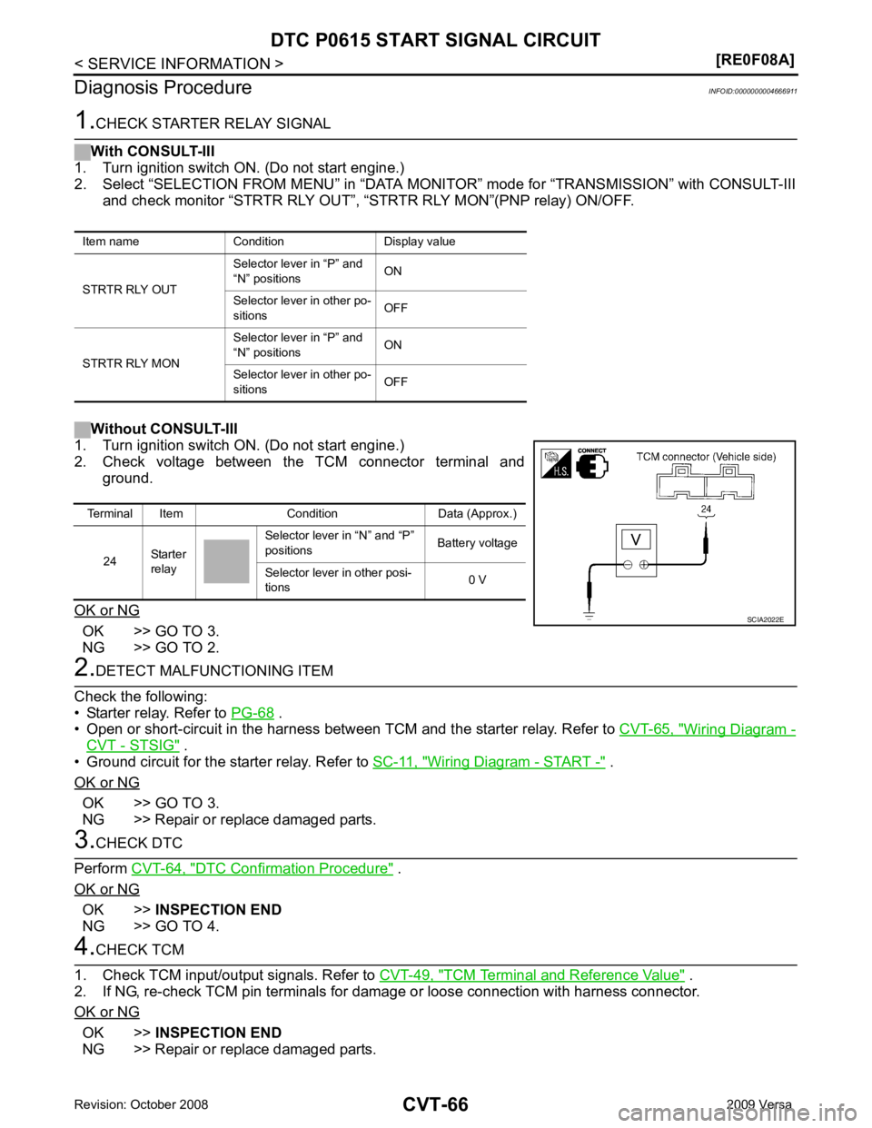
OK >> GO TO 3.
NG >> GO TO 2. .
• Open or short-circuit in the harness between TCM and the starter relay. Refer to CVT-65, " Wiring Diagram -
CVT - STSIG " .
• Ground circuit for the starter relay. Refer to SC-11, " Wiring Diagram - START - " .
OK or NG OK >> GO TO 3.
NG >> Repair or replace damaged parts. DTC Confirmation Procedure " .
OK or NG OK >>
INSPECTION END
NG >> GO TO 4. TCM Terminal and Reference Value " .
2. If NG, re-check TCM pin terminals for damage or loose connection with harness connector.
OK or NG OK >>
INSPECTION END
NG >> Repair or replace damaged parts.
Item name Condition Display value
STRTR RLY OUT Selector lever in “P” and
“N” positions ON
Selector lever in other po-
sitions OFF
STRTR RLY MON Selector lever in “P” and
“N” positions ON
Selector lever in other po-
sitions OFFTerminal Item Condition Data (Approx.)
24 Starter
relay Selector lever in “N” and “P”
positions Battery voltage
Selector lever in other posi-
tions 0 V
Page 1147 of 4331
![NISSAN LATIO 2009 Service Repair Manual CVT SYSTEM
CVT-203
< SERVICE INFORMATION >
[RE0F08B] D
E
F
G H
I
J
K L
M A
B CVT
N
O P
Hydraulic Control System
INFOID:0000000004305575
TCM Function INFOID:0000000004305576
The function of the TCM is NISSAN LATIO 2009 Service Repair Manual CVT SYSTEM
CVT-203
< SERVICE INFORMATION >
[RE0F08B] D
E
F
G H
I
J
K L
M A
B CVT
N
O P
Hydraulic Control System
INFOID:0000000004305575
TCM Function INFOID:0000000004305576
The function of the TCM is](/manual-img/5/57359/w960_57359-1146.png)
CVT SYSTEM
CVT-203
< SERVICE INFORMATION >
[RE0F08B] D
E
F
G H
I
J
K L
M A
B CVT
N
O P
Hydraulic Control System
INFOID:0000000004305575
TCM Function INFOID:0000000004305576
The function of the TCM is to:
• Receive input signals sent from various switches and sensors.
• Determine required line pressure, shifting point, and lock-up operation.
• Send required output signals to the step motor and the respective solenoids.
CONTROL SYSTEM OUTLINE The CVT senses vehicle operating conditions through vari ous sensors. It always controls the optimum shift
position and reduces shifting and lock-up shocks. SCIA1807E
SENSORS (or SIGNAL)
⇒TCM
⇒ACTUATORS
PNP switch
Accelerator pedal position signal
Closed throttle position signal
Engine speed signal
CVT fluid temperature sensor
Vehicle speed signal
Overdrive control signal
Stop lamp switch signal
Primary speed sensor
Secondary speed sensor
Secondary pressure sensor Shift control
Line pressure control
Primary pressure control
Secondary pressure control
Lock-up control
Engine brake control
Vehicle speed control
Fail-safe control
Self-diagnosis
CONSULT-III co mmunication
line
Duet-EA control
CAN system
On board diagnosis Step motor
Torque converter clutch solenoid
valve
Lock-up select solenoid valve
Line pressure solenoid valve
Secondary pressure solenoid
valve
Shift position indicator
O/D OFF indicator lamp
Starter relay
Page 1181 of 4331

CVT
N
O P
Diagnosis Procedure
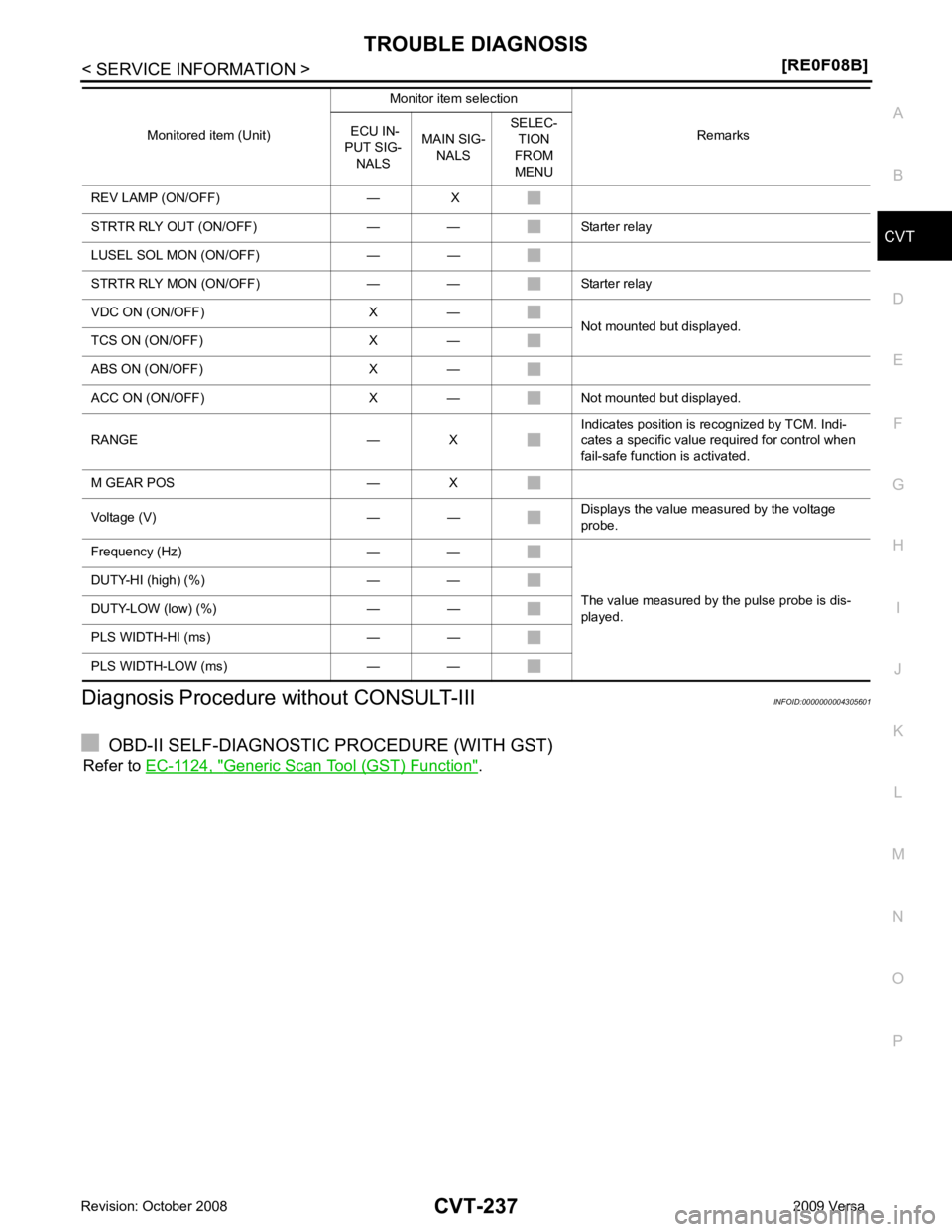
without CONSULT-III INFOID:0000000004305601
OBD-II SELF-DIAGNOSTIC PROCEDURE (WITH GST)
Refer to EC-1124, " Generic Scan Tool (GST) Function " .
REV LAMP (ON/OFF) — X
STRTR RLY OUT (ON/OFF) — — Starter relay
LUSEL SOL MON (ON/OFF) — —
STRTR RLY MON (ON/OFF) — — Starter relay
VDC ON (ON/OFF) X — Not mounted but displayed.
TCS ON (ON/OFF) X —
ABS ON (ON/OFF) X —
ACC ON (ON/OFF) X — Not mounted but displayed.
RANGE — X Indicates position is recognized by TCM. Indi-
cates a specific value required for control when
fail-safe function is activated.
M GEAR POS — X
Voltage (V) — — Displays the value measured by the voltage
probe.
Frequency (Hz) — —
The value measured by the pulse probe is dis-
played.
DUTY-HI (high) (%) — —
DUTY-LOW (low) (%) — —
PLS WIDTH-HI (ms) — —
PLS WIDTH-LOW (ms) — — Monitored item (Unit)
Monitor item selection
Remarks
ECU IN-
PUT SIG- NALS MAIN SIG-
NALS SELEC-
TION
FROM
MENU
Page 1361 of 4331

EC
A
N
O P
Diagnosis Procedure ...........................................
..
349
P0507 ISC SYSTEM ....................................... ..351
Description .......................................................... ..351
DTC Logic ........................................................... ..351
Diagnosis Procedure ........................................... ..351
P0603 ECM POWER SUPPLY ....................... ..353
Description .......................................................... ..353
DTC Logic ........................................................... ..353
Diagnosis Procedure ........................................... ..353
P0605 ECM ..................................................... ..355
Description .......................................................... ..355
DTC Logic ........................................................... ..355
Diagnosis Procedure ........................................... ..356
P0607 ECM ..................................................... ..357
Description .......................................................... ..357
DTC Logic ........................................................... ..357
Diagnosis Procedure ........................................... ..357
P0643 SENSOR POWER SUPPLY ............... ..358
DTC Logic ........................................................... ..358
Wiring Diagram ................................................... ..359
Diagnosis Procedure ........................................... ..359
P0850 PNP SWITCH ...................................... ..362
Description .......................................................... ..362
DTC Logic ........................................................... ..362
Component Function Check ................................ ..363
Wiring Diagram ................................................... ..364
Diagnosis Procedure ........................................... ..364
P1148 CLOSED LOOP CONTROL ................ ..367
DTC Logic ........................................................... ..367
P1217 ENGINE OVER TEMPERATURE ....... ..368
DTC Logic ........................................................... ..368
Component Function Check ................................ ..368
Diagnosis Procedure ........................................... ..369
P1225 TP SENSOR ........................................ ..372
Description .......................................................... ..372
DTC Logic ........................................................... ..372
Diagnosis Procedure ........................................... ..372
Special Repair Requirem ent .................................373
P1226 TP SENSOR ........................................ ..374
Description .......................................................... ..374
DTC Logic ........................................................... ..374
Diagnosis Procedure ........................................... ..374
Special Repair Requirem ent .................................375
P1421 COLD START CONTROL ................... ..376
Description .......................................................... ..376
DTC Logic ........................................................... ..376
Diagnosis Procedure ........................................... ..376
P1715 INPUT SPEED SENSOR (PRIMARY
SPEED SENSOR) .......................................... ..
378
Description .......................................................... ..378 DTC Logic ............................................................
..378
Diagnosis Procedure ........................................... ..378
P1805 BRAKE SWITCH ................................. 380
Description ........................................................... ..380
DTC Logic ............................................................ ..380
Wiring Diagram .................................................... ..381
Diagnosis Procedure ........................................... ..381
Component Inspection (Stop Lamp Switch) ........ ..383
P2100, P2103 THROTTLE CONTROL MO-
TOR RELAY .................................................... 384
Description ........................................................... ..384
DTC Logic ............................................................ ..384
Wiring Diagram .................................................... ..385
Diagnosis Procedure ........................................... ..385
P2101 ELECTRIC THROTTLE CONTROL
FUNCTION ....... ............................................... 388
Description ........................................................... ..388
DTC Logic ............................................................ ..388
Wiring Diagram .................................................... ..389
Diagnosis Procedure ........................................... ..389
Component Inspection ......................................... ..392
Special Repair Requiremen t ..................................392
P2118 THROTTLE CONTROL MOTOR ......... 393
Description ........................................................... ..393
DTC Logic ............................................................ ..393
Wiring Diagram .................................................... ..394
Diagnosis Procedure ........................................... ..394
Component Inspection ......................................... ..395
Special Repair Requiremen t ..................................396
P2119 ELECTRIC THROTTLE CONTROL
ACTUATOR ..................................................... 397
Description ........................................................... ..397
DTC Logic ............................................................ ..397
Diagnosis Procedure ........................................... ..397
Special Repair Requiremen t ..................................398
P2122, P2123 APP SENSOR ......................... 399
Description ........................................................... ..399
DTC Logic ............................................................ ..399
Wiring Diagram .................................................... ..400
Diagnosis Procedure ........................................... ..400
Component Inspection ......................................... ..402
Special Repair Requiremen t ..................................402
P2127, P2128 APP SENSOR ......................... 403
Description ........................................................... ..403
DTC Logic ............................................................ ..403
Wiring Diagram .................................................... ..404
Diagnosis Procedure ........................................... ..404
Component Inspection ......................................... ..406
Special Repair Requiremen t ..................................407
P2135 TP SENSOR ......................................... 408
Description ........................................................... ..408
DTC Logic ............................................................ ..408
Page 1375 of 4331

EC
A
N
O P
DTC P0850 PNP SWITCH ..............................
1401
Component Description ....................................... 1401
CONSULT-III Refe rence Value in Data Monitor
Mode ................................................................... 1401
On Board Diagnosis Logic .................................. 1401
DTC Confirmation Procedure .............................. 1401
Overall Function Check ....................................... 1402
Wiring Diagram ................................................... 1403
Diagnosis Procedure ........................................... 1404
DTC P1148 CLOSED LOOP CONTROL ....... 1407
On Board Diagnosis Logic .................................. 1407
DTC P1217 ENGINE OVER TEMPERATURE 1408
System Description ............................................. 1408
CONSULT-III Refe rence Value in Data Monitor
Mode ................................................................... 1409
On Board Diagnosis Logic .................................. 1409
Overall Function Check ....................................... 1409
Wiring Diagram ................................................... 1411
Diagnosis Procedure ........................................... 1412
Main 13 Causes of Overheating .......................... 1415
Component Inspection ........................................ 1416
DTC P1225 TP SENSOR ............................... 1417
Component Description ....................................... 1417
On Board Diagnosis Logic .................................. 1417
DTC Confirmation Procedure .............................. 1417
Diagnosis Procedure ........................................... 1417
Removal and Installation .....................................1418
DTC P1226 TP SENSOR ............................... 1419
Component Description ....................................... 1419
On Board Diagnosis Logic .................................. 1419
DTC Confirmation Procedure .............................. 1419
Diagnosis Procedure ........................................... 1419
Removal and Installation .....................................1420
DTC P1421 COLD START CONTROL .......... 1421
Description .......................................................... 1421
On Board Diagnosis Logic .................................. 1421
DTC Confirmation Procedure .............................. 1421
Diagnosis Procedure ........................................... 1421
DTC P1564 ASCD STEERING SWITCH ....... 1423
Component Description ....................................... 1423
CONSULT-III Refe rence Value in Data Monitor
Mode ................................................................... 1423
On Board Diagnosis Logic .................................. 1423
DTC Confirmation Procedure .............................. 1424
Wiring Diagram ................................................... 1425
Diagnosis Procedure ........................................... 1426
Component Inspection ........................................ 1428
DTC P1572 ASCD BRAKE SWITCH ............. 1429
Component Description ....................................... 1429
CONSULT-III Refe rence Value in Data Monitor
Mode ................................................................... 1429
On Board Diagnosis Logic .................................. 1429
DTC Confirmation Procedure .............................. 1430Wiring Diagram ....................................................
1431
Diagnosis Procedure ........................................... 1432
Component Inspection ......................................... 1436
DTC P1574 ASCD VEH ICLE SPEED SEN-
SOR ................................................................ 1438
Component Description ....................................... 1438
On Board Diagnosis Logic ................................... 1438
DTC Confirmation Procedure .............................. 1438
Diagnosis Procedure ........................................... 1438
DTC P1715 INPUT SPEED SENSOR (TUR-
BINE REVOLUTION SENSOR) ..................... 1440
Description ........................................................... 1440
CONSULT-III Reference Va lue in Data Monitor
Mode .................................................................... 1440
On Board Diagnosis Logic ................................... 1440
Diagnosis Procedure ........................................... 1440
DTC P1715 INPUT SPEED SENSOR (PRIMA-
RY SPEED SENSOR) ....................................
1441
Description ........................................................... 1441
CONSULT-III Reference Va lue in Data Monitor
Mode .................................................................... 1441
On Board Diagnosis Logic ................................... 1441
DTC Confirmation Procedure .............................. 1441
Diagnosis Procedure ........................................... 1441
DTC P1805 BRAKE SWITCH ........................ 1443
Description ........................................................... 1443
CONSULT-III Reference Va lue in Data Monitor
Mode .................................................................... 1443
On Board Diagnosis Logic ................................... 1443
DTC Confirmation Procedure .............................. 1443
Wiring Diagram .................................................... 1444
Diagnosis Procedure ........................................... 1445
Component Inspection ......................................... 1446
DTC P2100, P2103 THROTTLE CONTROL
MOTOR RELAY ............................................. 1447
Component Description ....................................... 1447
CONSULT-III Reference Va lue in Data Monitor
Mode .................................................................... 1447
On Board Diagnosis Logic ................................... 1447
DTC Confirmation Procedure .............................. 1447
Wiring Diagram .................................................... 1448
Diagnosis Procedure ........................................... 1449
DTC P2101 ELECTRIC THROTTLE CON-
TROL FUNCTION .......................................... 1451
Description ........................................................... 1451
On Board Diagnosis Logic ................................... 1451
DTC Confirmation Procedure .............................. 1451
Wiring Diagram .................................................... 1452
Diagnosis Procedure ........................................... 1453
Component Inspection ......................................... 1456
Removal and Installation ..................................... 1456
DTC P2118 THROTTLE CONTROL MOTOR 1457
Component Description ....................................... 1457
Page 1397 of 4331

EC
NP
O
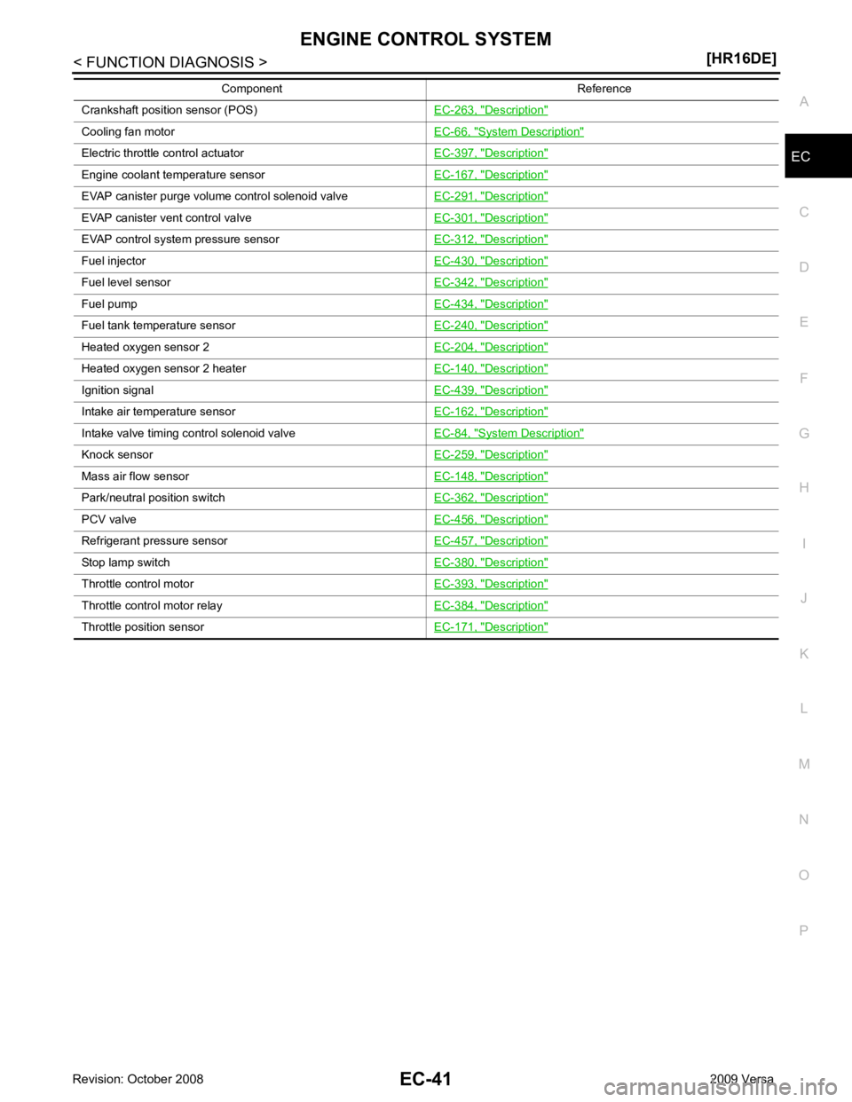
Crankshaft position sensor (POS)
EC-263, " Description "
Cooling fan motor
EC-66, " System Description "
Electric throttle control actuator
EC-397, " Description "
Engine coolant temperature sensor
EC-167, " Description "
EVAP canister purge volume control solenoid valve
EC-291, " Description "
EVAP canister vent control valve
EC-301, " Description "
EVAP control system pressure sensor
EC-312, " Description "
Fuel injector
EC-430, " Description "
Fuel level sensor
EC-342, " Description "
Fuel pump
EC-434, " Description "
Fuel tank temperature sensor
EC-240, " Description "
Heated oxygen sensor 2
EC-204, " Description "
Heated oxygen sensor 2 heater
EC-140, " Description "
Ignition signal
EC-439, " Description "
Intake air temperature sensor
EC-162, " Description "
Intake valve timing control solenoid valve
EC-84, " System Description "
Knock sensor
EC-259, " Description "
Mass air flow sensor
EC-148, " Description "
Park/neutral position switch
EC-362, " Description "
PCV valve
EC-456, " Description "
Refrigerant pressure sensor
EC-457, " Description "
Stop lamp switch
EC-380, " Description "
Throttle control motor
EC-393, " Description "
Throttle control motor relay
EC-384, " Description "
Throttle position sensor
EC-171, " Description "Component Reference
Page 1423 of 4331

EC
NP
O
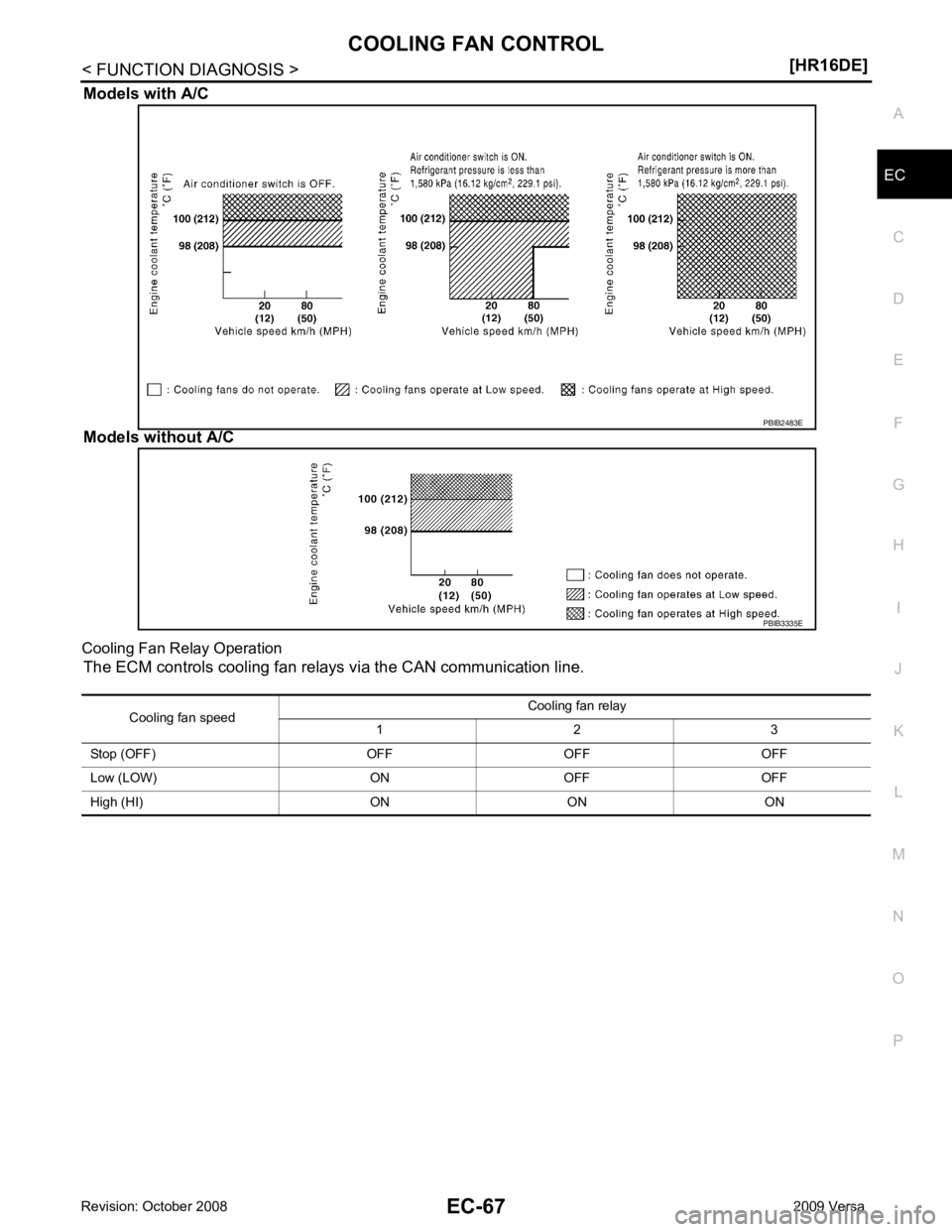
Models with A/C
Models without A/C
Cooling Fan Relay Operation The ECM controls cooling fan relays via the CAN communication line.
Page 1465 of 4331

EC
NP
O
Test Item
*: Leaving cooling fan OFF with CONSULT-III while engine is running may cause the engine to overheat.
DTC & SRT CONFIRMATION MODE
SRT STATUS Mode For details, refer to EC-90, " Diagnosis Description " .
SRT WORK SUPPORT Mode This mode enables a technician to drive a vehicle to set the SRT while monitoring the SRT status.
DTC WORK SUPPORT Mode TEST ITEM CONDITION JUDGMENT CHECK ITEM (REMEDY)
FUEL INJECTION • Engine: Return to the original
trouble condition
• Change the amount of fuel injec- tion using CONSULT-III. If trouble symptom disappears, see
CHECK ITEM. • Harness and connectors
• Fuel injector
• Air fuel ratio (A/F) sensor 1
IGNITION TIMING • Engine: Return to the original
trouble condition
• Timing light: Set
• Retard the ignition timing using
CONSULT-III. If trouble symptom disappears, see
CHECK ITEM. • Perform Idle Air Volume Learning.
POWER BALANCE • Engine: After warming up, idle
the engine.
• A/C switch OFF
• Selector lever: P or N position (A/ T), Neutral position (M/T)
• Cut off each fuel injector signal
one at a time using CONSULT-
III. Engine runs rough or dies.
• Harness and connectors
• Compression
• Fuel injector
• Power transistor
• Spark plug
• Ignition coil
COOLING FAN* • Ignition switch: ON
• Turn the cooling fan “LOW”, “HI”
and “OFF” using CONSULT-III. Cooling fan moves and stops.
• Harness and connectors
• IPDM E/R (Cooling fan relay)
• Cooling fan motor
ENG COOLANT
TEMP • Engine: Return to the original
trouble condition
• Change the engine coolant tem-
perature using CONSULT-III. If trouble symptom disappears, see
CHECK ITEM. • Harness and connectors
• Engine coolant temperature sen- sor
• Fuel injector
FUEL PUMP RELAY • Ignition switch: ON (Engine
stopped)
• Turn the fuel pump relay “ON”
and “OFF” using CONSULT-III
and listen to operating sound. Fuel pump relay makes the operat-
ing sound. • Harness and connectors
• Fuel pump relay
PURG VOL CONT/V • Engine: After warming up, run
engine at 1,500 rpm.
• Change the EVAP canister purge volume control solenoid
valve opening percent using
CONSULT-III. Engine speed changes according
to the opening percent. • Harness and connectors
• Solenoid valve
FUEL/T TEMP SEN • Change the fuel tank temperature using CONSULT-III.
VENT CONTROL/V • Ignition switch: ON (Engine
stopped)
• Turn solenoid valve “ON” and “OFF” using th e CONSULT-III
and listen to operating sound. Solenoid valve makes an operating
sound. • Harness and connectors
• Solenoid valve
V/T ASSIGN ANGLE • Engine: Return to the original
trouble condition
• Change intake valve timing us-
ing CONSULT-III. If trouble symptom disappears, see
CHECK ITEM. • Harness and connectors
• Intake valve timing control sole- noid valve